The VF series consists of gearboxes and geared -motors ... - Famco
The VF series consists of gearboxes and geared -motors ... - Famco
The VF series consists of gearboxes and geared -motors ... - Famco

You also want an ePaper? Increase the reach of your titles
YUMPU automatically turns print PDFs into web optimized ePapers that Google loves.
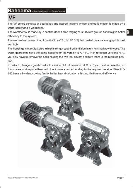
<strong>VF</strong><strong>The</strong> <strong>VF</strong> <strong>series</strong> <strong>consists</strong> <strong>of</strong> <strong>gearboxes</strong> <strong>and</strong> <strong>geared</strong> -<strong>motors</strong> whose cinematic motion is made by aworm-screw <strong>and</strong> a wormgear.<strong>The</strong> wormscrew is made by a cast hardened drop forging <strong>of</strong> CK45 with ground flank to give betterefficiency to the system.<strong>The</strong> wormwheel is machined from G-CU sn12 (UNI 70 B-2) that casted on a nodular graphite castiron hob.<strong>The</strong> housings is manufactured in high strength cast -iron <strong>and</strong> aluminium for small power types. <strong>The</strong>worm <strong>gearboxes</strong> have the same housing for the version N-A-F-FC-P; in to obtain versions N-A ,you only have to remove the bolts holding the two foot covers <strong>and</strong> turn them to the required position.In order to change a gearboxed with version N-A into version F-FC or P, you must remove the tw<strong>of</strong>oot covers <strong>and</strong> replace them with the 2 covers corresponding to the required version. Size 210-250 have a bivalent cooling fan for better heat dissipation effecting life time <strong>and</strong> efficiency.DOCUMENT CODE:RO04-05 REVISION NO.:03Page 11
DESIGNATIONN.B.: Geared <strong>motors</strong> can be supplied without the motor (P.A.M) but when ordering the <strong>motors</strong>izemust be specified.SERVICE FACTOR s.f. FOR THE GEARBOXES <strong>VF</strong>-R<strong>VF</strong>-<strong>VF</strong>/<strong>VF</strong> SERIESN.B. : the above values must be multiplied by 1.2 in case <strong>of</strong>:- Combustion engine drive- Reversing operation- Instantaneous overloadsPage 12DOCUMENT CODE:RO04-05 REVISION NO.:03
GUIDE TO THE SELECTION OF THE WORM GEARBOXESSome applications require total reversing or total non-reversing <strong>of</strong> the gearbox, therefore the behavior<strong>of</strong> these <strong>gearboxes</strong> when they are back-driven must be analyzed . one <strong>of</strong> the paramountfactors determinating the reversing or non -reversing <strong>of</strong> worm <strong>gearboxes</strong> is the efficiency, whichdepends upon the following parameters:- helix angle(γ),- Type <strong>of</strong> materials in contact,- Tooth from accuracy,- Surface finishing,- Lubrication,- Slipping speed.Actually during planning <strong>and</strong> design there is the tendency to reach ideal contact conditions lookingfor higher <strong>and</strong> higher efficiencies but it is necessary to look for the best compromise solution toobtain a good efficiency <strong>and</strong> keep acceptable non- reversing conditions in the higher reductionratios(70-80-100).To look for the most ideal solution which meets the requirement <strong>of</strong> more or less accentuated toexamine the difference between static <strong>and</strong> dynamic non-reversing.STATIC NON-REVERSINGThis is the easiest condition to get, it is not possible to rotate the low speed shaft. However in thecase <strong>of</strong> vibrations slow movements cannot be excluded.<strong>The</strong> theoretical condition to get the static non-reversing is the follows: (Refer to page 15, columnη ) dη s< 0.4 ÷ 0.5where η sis the static efficiency.Of course the opposite condition(i.e. static reversing ) will beη s< 0.5Considering that higher η smeans better reversing conditions as here under indicated.DYNAMIC NON-REVERSINGIt is the most difficult condition to get because it is directly influenced by rotating speed, efficiency<strong>and</strong> continuous vibrations <strong>of</strong> the load. its main characteristic is an immediate stop <strong>of</strong> rotation whenthere is no more drive on the wormscrew. <strong>The</strong> theoretical condition to attain it,isη d< 0.5DOCUMENT CODE:RO04-05 REVISION NO.:03Page 13
GUIDE TO THE SELECTION OF THE WORM GEARBOXESWhere η dis the gearbox efficiency in the actual operating conditions. the opposite conditions(i.e.dynamic reversing)isη d> 0.5<strong>The</strong> following scheme is an analysis <strong>of</strong> the different reversing degrees as a function <strong>of</strong> the helixangle(γ).Of course this is only indicative data as with the same helix angle we can have a more or lessaccentuated non- reversing affect if the a.m. factors.Since total dynamic non -reversing is impossible, if this is a requirement it is necessary to use abrake to avoid motion.Page 14DOCUMENT CODE:RO04-05 REVISION NO.:03
GUIDE TO THE SELECTION OF THE WORM GEARBOXESCHARACTERISTICS OF WORM AND WHEE L TOOTHINGDOCUMENT CODE:RO04-05 REVISION NO.:03Page 15
GUIDE TO THE SELECTION THE WORM GEARBOXESEFFICIENCYIt is very important to consider the efficiency for the selection <strong>of</strong> the worm <strong>gearboxes</strong>. For intermittentduty applications (hoistings, operations, etc.) it is necessary to increase the motor’s power inorder to compensate the low efficiency <strong>of</strong> the gearbox during the starting. For this purpose weremind you that the best value appears after some hours <strong>of</strong> running-in <strong>and</strong> it is reached in thesteady state operating <strong>gearboxes</strong>.<strong>The</strong> value M2 (daNm) indicated on the catalogue, are calculated considering the efficiency <strong>of</strong> thesteady state <strong>gearboxes</strong>.<strong>The</strong> graph below indicates the different torque among <strong>VF</strong>-R<strong>VF</strong>-<strong>VF</strong>.../ <strong>VF</strong> <strong>of</strong> the same size (ex.<strong>VF</strong>62-R<strong>VF</strong>62-<strong>VF</strong>30/62).If the ratios <strong>of</strong> 2 different types are overlapped, the best choice, in particular for heavy applicationswith frequent shocks <strong>and</strong> overload starts (f.i.hoistings), is the type with the higher torque(<strong>and</strong>efficiency).DIRECTION OF ROTATIONFor all the worm <strong>gearboxes</strong> the direction <strong>of</strong> the screw is right-h<strong>and</strong>.Page 16DOCUMENT CODE:RO04-05 REVISION NO.:03
GUIDE TO THE SELECTION THE WORM GEARBOXESLUBRICATIONOur worm <strong>gearboxes</strong> are lubricated differently , depending upon the power rating .<strong>The</strong>re are two groups:1) <strong>VF</strong>27- <strong>VF</strong> 30- <strong>VF</strong>44- <strong>VF</strong> 49- <strong>VF</strong> 62- <strong>VF</strong> 86-2) <strong>VF</strong> 110- <strong>VF</strong> 130- <strong>VF</strong> 150- <strong>VF</strong> 185-<strong>VF</strong> 210-<strong>VF</strong> 250<strong>The</strong> small <strong>and</strong> medium power <strong>gearboxes</strong> <strong>of</strong> the first group are maintenance free, being filled withmounting position (except for the V5 <strong>and</strong> V6 mounting positions for which it is necessary contactingour TECH. DEPARTMENT to value the working conditions).<strong>The</strong> medium <strong>and</strong> large power <strong>gearboxes</strong> <strong>of</strong> the second group are oil lubricated.<strong>The</strong>y are supplied empty <strong>and</strong> must be filled before use with the tight quantity <strong>of</strong> oil. <strong>The</strong>se <strong>gearboxes</strong>are therefore fitted with filling, draining <strong>and</strong> oil level plugs <strong>and</strong> whenever a mounting positiondifferent from B3 is required, it must be specified on the order.AMOUNT OF LUBRICANT FOR <strong>VF</strong> GEARBOXESQuantities shown in table A are supplied from factory <strong>and</strong> provide adequate lubrication regardless toactual mounting position.the above quantities are indicative <strong>and</strong> refer to the mounting position B3.<strong>The</strong>y are used also for the corresponding sizes <strong>of</strong> <strong>gearboxes</strong> R<strong>VF</strong> ( excluding the primary reduction<strong>and</strong> <strong>VF</strong>/<strong>VF</strong>.DOCUMENT CODE:RO04-05 REVISION NO.:04Page 17
MOUNTING POSITIONSPage 18DOCUMENT CODE:RO04-05 REVISION NO.:03
TECHNICAL CHARACTERISTICSWORM GEARED MOTORM<strong>VF</strong> 27n 1 = 1400WORM GEARBOX<strong>VF</strong> 27When speed n 1>1400 see on page 5 <strong>and</strong> 6.n 1 = 900 n 1 = 500OVERALL DIMENSIONSELECTRIC MOTORSM<strong>VF</strong> 27/N<strong>VF</strong> 27/NM<strong>VF</strong> 27/A<strong>VF</strong> 27/AM<strong>VF</strong> 27/F<strong>VF</strong> 27/FDOCUMENT CODE:RO04-05 REVISION NO.:03Page 19
CHARACTERISTICS OF M<strong>VF</strong> SERIES MOTORIZED WORMn 1 = 1400GEARBOXESWhen speed n 1>1400 see on page 5 <strong>and</strong> 6.Page 20DOCUMENT CODE:RO04-05 REVISION NO.:03
CHARACTERISTICS OF <strong>VF</strong> SERIES WORM GEARBOXESn 1 = 1400When speed n 1>1400 see on page 5 <strong>and</strong> 6.DOCUMENT CODE:RO04-05 REVISION NO.:03Page 21
CHARACTERISTICS OF <strong>VF</strong> SERIES WORM GEARBOXESn 1 = 900Page 22DOCUMENT CODE:RO04-05 REVISION NO.:04
CHARACTERISTICS OF <strong>VF</strong> SERIES WORM GEARBOXESn 1 = 500DOCUMENT CODE:RO04-05 REVISION NO.:03Page 23
OVERALL DIMENSIONSMOTOR VERSION B5MOTOR VERSION B14M<strong>VF</strong> .../NM<strong>VF</strong> .../AM<strong>VF</strong> .../FM<strong>VF</strong> .../FCM<strong>VF</strong> .../PN.B.: from size 30 to 86, P version is supplied as st<strong>and</strong>ard with two P covers.From size 110 to 185, P version is supplied as st<strong>and</strong>ard with only one P cover (the customer cansee the real position <strong>of</strong> P cover into correspondent photography).Page 24DOCUMENT CODE:RO04-05 REVISION NO.:03
OVERALL DIMENSIONSM<strong>VF</strong>...N.B.• <strong>The</strong> number which follows the reference M<strong>VF</strong> indicates the center distance between theworm shaft <strong>and</strong> the wheel center <strong>of</strong> the <strong>geared</strong> motor.• Motorized worm <strong>gearboxes</strong> are supplied with hollow output shaft as st<strong>and</strong>ard.• Single or double sided output shafts are available on request as shown in page 32.• <strong>The</strong> types 30/p, 44/p, 48/p have the M6×9 tapped holes rotated by 45° from the cataloguepicture.• Dimensions X <strong>and</strong> Y vary according to the <strong>motors</strong>ize(page 103,104).• On request P version can be supplied with reaction arm(see page 32).DOCUMENT CODE:RO04-05 REVISION NO.:04Page 25
OVERALL DIMENSIONS<strong>VF</strong> .../N<strong>VF</strong> .../A<strong>VF</strong> .../F<strong>VF</strong> .../FC<strong>VF</strong> .../PN.B.: From size 30 to 86, P version is supplied as st<strong>and</strong>ard with two P covers.From size 110 to 185,P version is supplied as st<strong>and</strong>ard with only one P cover (the customer cansee the real position <strong>of</strong> P cover into correspondent photography).Page 26DOCUMENT CODE:RO04-05 REVISION NO.:03
OVERALL DIMENSIONS<strong>VF</strong>...N.B.• <strong>The</strong> number which follows the reference <strong>VF</strong> indicates the center distance between the worm shaft<strong>and</strong> the wheel center.• Worm <strong>gearboxes</strong> are supplied with single - sided input shaft.• Worm <strong>gearboxes</strong> are normally supplied with hollow output shaft; on customer request single ordouble sided output shafts are available on request as shown on page 32.• <strong>The</strong> types 30/P, 44/P, 49/P have the M6×9 tapped holes rotates by 45° from the catalogue picture.•On request, P version can be supplied with reaction arm(see page 32).DOCUMENT CODE:RO04-05 REVISION NO.:04Page 27
OVERALL DIMENSIONS Size 210-250<strong>VF</strong> .../N<strong>VF</strong> .../A<strong>VF</strong> .../PM<strong>VF</strong> .../NM<strong>VF</strong> .../AM<strong>VF</strong> .../PN.B•We supply P version as st<strong>and</strong>ard with two«P» covers.•<strong>The</strong> number which follows the reference M<strong>VF</strong> <strong>and</strong> <strong>VF</strong> indicates the center distancebetween the worm shaft as st<strong>and</strong>ard.•Worm <strong>gearboxes</strong> are supplied with hollow output shaft as st<strong>and</strong>ard.•Single or double sided output shafts are available on request as shown on page32.•Dimensions X <strong>and</strong> Y vary according to the <strong>motors</strong>ize <strong>of</strong> the motor (page 103,104).•On request P version can be supplied with reaction arm (see page 32).Page 28DOCUMENT CODE:RO04-05 REVISION NO.:04
TABLE OF KEYWAY SIZESDIMENSIONS OF TAPPED HOLES ONINPUT AND OUTPUT SHAFTSDOCUMENT CODE:RO04-05 REVISION NO.:04Page 29
TABLE OF MAXIMUM PERMISSIBLE RADIAL LOAD ON OUTPUT SHAFT(expressed in daN)N.B.Dimensions <strong>of</strong> projecting <strong>of</strong> the output shaft are reported on the accessories table.(page 32)TABLE OF MAXIMUM PERMISSIBLE RADIAL LOADS ON INPUT SHAFTS(expressed in daN)Page 30DOCUMENT CODE:RO04-05 REVISION NO.:03
CALCULATION OF RADIAL LOAD ON OUTPUT AND INPUT SHAFTSR= Radial load(daN)R= 2000.M.KM= Torque(daNm)DD= Diameter (mm) <strong>of</strong> chain wheel, gear ,belt, pulley V,etc.K=1 - chain wheel1.25-Gear1.5 -Belt pulley VN.B.<strong>The</strong> above resulting value <strong>of</strong> R must be lower than the value <strong>of</strong> the radial load for this type <strong>of</strong>gearbox.• <strong>The</strong> value <strong>of</strong> the radial loads indicated in the table are nominal <strong>and</strong> are valid for loads acting ata distance ,from the shoulder <strong>of</strong> the shaft, equal to half the length <strong>of</strong> the shaft itself.• <strong>The</strong> value for the maximum allowable thrust load is equal to 1/5th <strong>of</strong> the value indicated in thetable.• <strong>The</strong> values referring to 300 rpm(input shaft) <strong>and</strong> to 14 rpm(output shaft) are the maximumpermissible overhung loads the gearbox will withst<strong>and</strong>.• Loading for speeds which do not appear in the table may be obtained by interpolation.• It is preferable to mount the pulley or gearwheel as near as possible to the shoulder <strong>of</strong> the shaft.• In the case <strong>of</strong> double projecting shafts, the loading which may be taken by each <strong>of</strong> the ends isequal to 2/3rd <strong>of</strong> the value in the table, if the two loads are equal <strong>and</strong> operate in the samedirection.DOCUMENT CODE:RO04-05 REVISION NO.:03Page 31
ACCESSORIES FOR <strong>VF</strong>, R<strong>VF</strong> AND <strong>VF</strong>/<strong>VF</strong>OUTPUT SHAFTS FOR WORM GERBOXESSINGLE OUTPUT SHAFTSizes 30÷ 250DOUBLE OUTPUT SHAFTSizes 30÷ 250N.B. keys <strong>and</strong> holes threaded according to the table on page 29.REACTION ARM FOR <strong>VF</strong>.../P VERSIONPage 32DOCUMENT CODE:RO04-05 REVISION NO.:04
OVERALL DIMENSIONS OF THE WORM/WHEEL <strong>VF</strong>,R<strong>VF</strong> AND <strong>VF</strong>/<strong>VF</strong>N.B.<strong>The</strong> D <strong>and</strong> G dimensions indicated are the maximum that may be found in the various ratioes.SPECIAL VERSIONS <strong>VF</strong>-R<strong>VF</strong>-<strong>VF</strong>/<strong>VF</strong>AVAILABLE VERSION N-A-F-FC-PBeing a special version, the components are machined only if request, therefore their availabilityhas to be verificated with our SALES DEPARTMENT.DOCUMENT CODE:RO04-05 REVISION NO.:04Page 33
POSSIBLE ASSEMBLINGSAll <strong>of</strong> our <strong>geared</strong> <strong>motors</strong> can be assembled with electric <strong>motors</strong> <strong>series</strong> UNEL MEC B5(see table on page 103,104). <strong>The</strong> types M<strong>VF</strong>30,M<strong>VF</strong>44, <strong>and</strong> M<strong>VF</strong>49, will be suppliedwith motor adaptor integral with the housing (excluding the M<strong>VF</strong>49 <strong>motors</strong>ize 63-B14).At customer’s request all the <strong>motors</strong>ize <strong>gearboxes</strong> shown with can be fitted with B14motor adaptor.N.B.M<strong>VF</strong>27 fitted with <strong>motors</strong> <strong>of</strong> 0.08 <strong>and</strong> 0.12 HP can be supplied only completewith motor. <strong>The</strong>se <strong>motors</strong> are not conform to a st<strong>and</strong>ard being manufactured byRahnama Company.All the <strong>geared</strong> <strong>motors</strong> whose <strong>motors</strong>ize is marked will be with modified keyway.Page 34DOCUMENT CODE:RO04-05 REVISION NO.:03
<strong>VF</strong>/<strong>VF</strong>Two worm <strong>gearboxes</strong> <strong>VF</strong> <strong>series</strong> assembled together by means <strong>of</strong> a connection flange are validsolution to get high ratios. <strong>The</strong> possibly to change the positions <strong>of</strong> the 2 <strong>gearboxes</strong> makes this unitvery versatile . It is preferable to select the double worm <strong>gearboxes</strong>, which works at very lowspeed, considering the required torque M2 > = M × s.f. as <strong>of</strong>ten the installed power exceeds theabsorbed power.DOCUMENT CODE:RO04-05 REVISION NO.:03Page 49
DESIGNATION<strong>VF</strong>N.B. Geared <strong>motors</strong> can be supplied without the motor (P.A.M.), but when ordering, the <strong>motors</strong>izemust be specified.DIRECTION OF ROTATIONMOUNTING POSITIONSPlease always specify mounting position referring to the second <strong>VF</strong> gearbox according to thetable on page 18.LUBRICATION<strong>The</strong> lubrication is the same <strong>of</strong> the corresponding <strong>VF</strong> <strong>gearboxes</strong> (page 17).Page 50DOCUMENT CODE:RO04-05 REVISION NO.:03
MOUNTING POSITIONSDOCUMENT CODE:RO04-05 REVISION NO.:03Page 51
CHARACTERISTICS OF MOTORIZED DOUBLE REDUCTION GEARBOXES n 1 = 1400FOR HIGHER RATIOS (WORM/WORM) M<strong>VF</strong>.../<strong>VF</strong>... SERIES When speed n 1>1400 see on page 5 <strong>and</strong> 6.<strong>The</strong> power indicated with * are higher thanthose transmissible by the gearbox thereforethe selection must be made according to thetorque M 2.Page 52DOCUMENT CODE:RO04-05 REVISION NO.:03
CHARACTERISTICS OF DOUBLE REDUCTION GEARBOXES FOR HIGHER n 1 = 1400RATIOS (WORM/WORM)<strong>VF</strong>.../<strong>VF</strong>... SERIES when speed n 1>1400 see on page 5 <strong>and</strong> 6.N.B. : On customer’s request the double <strong>gearboxes</strong><strong>VF</strong>.../ <strong>VF</strong>... in some cases , can be suppliedwith higher ratios than the st<strong>and</strong>ardones(see below descriptions).<strong>VF</strong>.../<strong>VF</strong>...From size 62/130 to size 130/250 it is possibleto supply ratioes up to 1:10.000.DOCUMENT CODE:RO04-05 REVISION NO.:03Page 53
CHARACTERISTICS OF DOUBLE REDUCTION GEARBOXES FORHIGHER RATIOS (WORM/WORM) <strong>VF</strong>.../<strong>VF</strong>... SERIESn 1 = 900Page 54DOCUMENT CODE:RO04-05 REVISION NO.:03
CHARACTERISTICS OF DOUBLE REDUCTION GEARBOXESFOR HIGHER RATIOS (WORM/WORM) <strong>VF</strong>.../<strong>VF</strong>... SERIESn 1 = 500DOCUMENT CODE:RO04-05 REVISION NO.:03Page 55
OVERALL DIMENSIONSM<strong>VF</strong> .../<strong>VF</strong>.../AM<strong>VF</strong> .../<strong>VF</strong>.../FM<strong>VF</strong> .../<strong>VF</strong>.../FCM<strong>VF</strong> .../<strong>VF</strong>.../PN.B.:•From size 44 to 86 version is supplied as st<strong>and</strong>ard with two P cover.•From size 110 to 185 , P version is supplied as st<strong>and</strong>ard with only one P cover (the customer cansee the real position <strong>of</strong> P cover into correspondent photography).•<strong>The</strong> double motorized worm <strong>gearboxes</strong> are supplied with hollow output shaft as st<strong>and</strong>ard.•Only on customer’s request will be supplied single or double shafts(page 32).•On customer’s request, the P version is supplied complete with reaction arm (page 32).•Keys <strong>and</strong> threaded holes dimensions on the top <strong>of</strong> input <strong>and</strong> output shafts are on page 60.Page 56DOCUMENT CODE:RO04-05 REVISION NO.:03
OVERALL DIMENSIONSM<strong>VF</strong> 130/210AM<strong>VF</strong> 130/250AM<strong>VF</strong> 130/210PM<strong>VF</strong> 130/250PN.B. Sizes 210-250 in P version are supplied as st<strong>and</strong>ad with two P cover.M<strong>VF</strong>.../<strong>VF</strong>...N.B. Dimensions X <strong>and</strong> Y vary according to size <strong>of</strong> the motor(page 103,104).<strong>The</strong> types 30/44 <strong>and</strong> 30/49 P have the M6x9 tapped holes placed in a circle by 45° from each other .DOCUMENT CODE:RO04-05 REVISION NO.:04Page 57
OVERALL DIMENSIONS<strong>VF</strong> .../<strong>VF</strong>.../A<strong>VF</strong> .../<strong>VF</strong>.../F<strong>VF</strong> .../<strong>VF</strong>.../FC<strong>VF</strong> .../<strong>VF</strong>.../PN.B.:•From size 44 to 86,P version is supplied as st<strong>and</strong>ard with two P cover.•From size 110 to 185, P version is supplied as st<strong>and</strong>ard with only one P cover (the customer cansee the real position <strong>of</strong> P cover into correspondent photography).•<strong>The</strong> double motorized worm <strong>gearboxes</strong> are supplied with hollow output shaft as st<strong>and</strong>ard.•Only on customer’s request will be supplied single or double shafts(page 32).•On customer’s request, the P version is supplied complete with reaction arm (page 32).•Keys <strong>and</strong> threaded holes dimensions on the top <strong>of</strong> input <strong>and</strong> output shafts are on page 60.Page 58DOCUMENT CODE:RO04-05 REVISION NO.:03
OVERALL DIMENSIONS<strong>VF</strong>130/210A<strong>VF</strong>130/250A<strong>VF</strong>130/210P<strong>VF</strong>130/250PN.B. Sizes 210-250 in P version are supplied as st<strong>and</strong>ad with two P cover.<strong>VF</strong>.../<strong>VF</strong>...• <strong>The</strong> types 30/44 <strong>and</strong> 30/49 P have the M6x9 tapped holes placed in a circle by 45°from each other.DOCUMENT CODE:RO04-05 REVISION NO.:04Page 59
TABLE OF KEYWAY SIZESDIMENSIONS OF TAPPED HOLES ON INPUT AND OUTPUT SHAFTSMAX. ADMISSIBLE RADIAL LOADS ON INPUT AND OUTPUT SHAFTS.<strong>The</strong> values <strong>of</strong> radial <strong>and</strong> thrust loads are the same <strong>of</strong> the corresponding <strong>VF</strong> <strong>gearboxes</strong> (see page 30).POSSIBLE ASSEMBLINGS<strong>The</strong>y are the same <strong>of</strong> the corresponding <strong>VF</strong> <strong>gearboxes</strong> <strong>and</strong> are on page 34.Ofcourse they refer to the first <strong>gearboxes</strong>.Page 60DOCUMENT CODE:RO04-05 REVISION NO.:04
Dear CustomerYour propensity to choose our products is sincerelymost <strong>of</strong> grateful. Quality promotion <strong>and</strong> achieving higherdesirability needs useful <strong>and</strong> wise guidance, <strong>and</strong> anycomment in this respect would be kindly appreciated.Thank you in advance <strong>and</strong> we remain,Yours very affectionately,Saeid RahnamaManaging DirectorDOCUMENT CODE:RO04-05 REVISION NO.:03