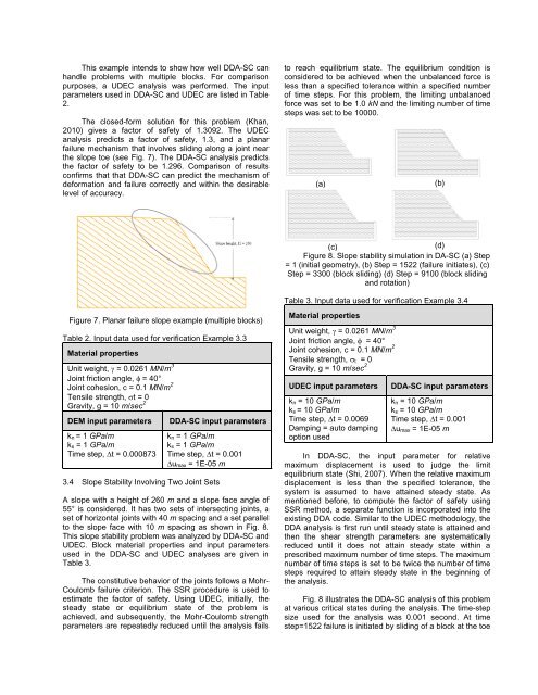
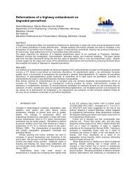
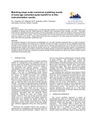
This example intends to show how well DDA-SC canhandle problems with multiple blocks. For comparisonpurposes, a UDEC analysis was performed. The inputparameters used in DDA-SC and UDEC are listed in Table2.The closed-form solution for this problem (Khan,2010) gives a factor of safety of 1.3092. The UDECanalysis predicts a factor of safety, 1.3, and a planarfailure mechanism that involves sliding along a joint nearthe slope toe (see Fig. 7). The DDA-SC analysis predictsthe factor of safety to be 1.296. Comparison of resultsconfirms that that DDA-SC can predict the mechanism ofdeformation and failure correctly and within the desirablelevel of accuracy.to reach equilibrium state. The equilibrium condition isconsidered to be achieved when the unbalanced force isless than a specified tolerance within a specified numberof time steps. For this problem, the limiting unbalancedforce was set to be 1.0 kN and the limiting number of timesteps was set to be 10000.(a)(b)(c)(d)Figure 8. Slope stability simulation in DA-SC (a) Step= 1 (initial geometry), (b) Step = 1522 (failure initiates), (c)Step = 3300 (block sliding) (d) Step = 9100 (block slidingand rotation)Table 3. Input data used for verification Example 3.4Figure 7. Planar failure slope example (multiple blocks)Table 2. Input data used for verification Example 3.3Material propertiesUnit weight, = 0.0261 MN/m 3Joint friction angle, = 40°Joint cohesion, c = 0.1 MN/m 2Tensile strength, t = 0Gravity, g = 10 m/sec 2DEM input parametersk n = 1 GPa/mk s = 1 GPa/mTime step, ∆t = 0.000873DDA-SC input parametersk n = 1 GPa/mk s = 1 GPa/mTime step, ∆t = 0.001u max = 1E-05 m3.4 Slope Stability Involving Two Joint SetsA slope with a height of 260 m and a slope face angle of55° is considered. It has two sets of intersecting joints, aset of horizontal joints with 40 m spacing and a set parallelto the slope face with 10 m spacing as shown in Fig. 8.This slope stability problem was analyzed by DDA-SC andUDEC. Block material properties and input parametersused in the DDA-SC and UDEC analyses are given inTable 3.The constitutive behavior of the joints follows a Mohr-Coulomb failure criterion. The SSR procedure is used toestimate the factor of safety. Using UDEC, initially, thesteady state or equilibrium state of the problem isachieved, and subsequently, the Mohr-Coulomb strengthparameters are repeatedly reduced until the analysis failsMaterial propertiesUnit weight, = 0.0261 MN/m 3Joint friction angle, = 40°Joint cohesion, c = 0.1 MN/m 2Tensile strength, t = 0Gravity, g = 10 m/sec 2UDEC input parametersk n = 10 GPa/mk s = 10 GPa/mTime step, ∆t = 0.0069Damping = auto dampingoption usedDDA-SC input parametersk n = 10 GPa/mk s = 10 GPa/mTime step, ∆t = 0.001u max = 1E-05 mIn DDA-SC, the input parameter for relativemaximum displacement is used to judge the limitequilibrium state (Shi, 2007). When the relative maximumdisplacement is less than the specified tolerance, thesystem is assumed to have attained steady state. Asmentioned before, to compute the factor of safety usingSSR method, a separate function is incorporated into theexisting DDA code. Similar to the UDEC methodology, theDDA analysis is first run until steady state is attained andthen the shear strength parameters are systematicallyreduced until it does not attain steady state within aprescribed maximum number of time steps. The maximumnumber of time steps is set to be twice the number of timesteps required to attain steady state in the beginning ofthe analysis.Fig. 8 illustrates the DDA-SC analysis of this problemat various critical states during the analysis. The time-stepsize used for the analysis was 0.001 second. At timestep=1522 failure is initiated by sliding of a block at the toe
CPU time (min.)of the slope. DDA-SC predicts a failure mechanism whichis initiated by sliding and then by rotation of the blocknearest to the slope toe. DDA-SC predicted a factor ofsafety of 1.82. The failure mechanism predicted by DDA-SC is shown in Fig. 9(a). The UDEC analysis predicted asimilar failure mechanism, and a factor of safety of 1.74shown in Fig. 9(b). The difference between the factors ofsafety predicted by DDA-SC and UDEC is approximately3.5%.(a)(b)Figure 9. Comparison of slope failure mechanism in DDA-SC and DEM (a) Slope failure predicted by DDA-SC (b)Slope failure predicted by UDECFor comparison purposes, this slope problem wasalso analyzed by DDA-Shi, which predicts a similar failuremechanism and a factor of safety of 1.80. The final resultsobtained by UDEC, DDA-Shi and DDA-SC are provided inTable 4. Comparison of results confirms that hard contactand soft contact logics used in enforcement of contactconstraints lead to convergence to one physicallyadmissible solution. In terms of computational speed,DDA-Shi took approximately 25 minutes of CPU time toattain limit equilibrium state whereas DDA-SC tookapproximately 6 minutes (refer to Table 4). Resultsindicate that soft contact implementation improved thecomputational efficiency of DDA. DDA-SC, however, couldnot match the speed of DEM which reached equilibrium inless than one minute.Table 4. Comparison of results from DDA and UDEC forExample 3.4AspectDDA- DDA-Shi SCUDECProblem Blocks 482 482 468size DOFs 1446 1446 1404AnalysisresultFailuremechanismBlockslidingandrotationBlockslidingandrotationBlockslidingandrotationFactor ofsafety1.80 1.82 1.74Steady25 6 1CPU time(min.)statePost failure10 m 47.3 10.4 2.820 m 65.4 17.8 4.330 m 78.7 25.3 5.740 m 98.2 29.6 7.2Average25 m 72.4 20.8 5.0It has been discussed that application of discreteelement techniques is most desired when largedeformation, including sliding or rotation of blocks are adominant mechanism in the response. Therefore, thecapability and efficiency of discrete element methods inthe post-failure regime is an integral part of the evaluationof discrete methods. The efficiency of the DDA solution inthe post-failure regime is investigated by recording theCPU time for four different “physical times” (see Table 4).The times associate with a block displacement of 10 m, 20m, 30 m, and 40 m.The displacement versus CPU time for DDA-SC,UDEC, and DDA-Shi solutions are plotted in Fig. 10. Thisfigure shows that compared to DDA-Shi, DDA-SC hasimproved the computational speed by a factor of four inmodelling the post-failure behaviour. However, UDEC,which is based on the distinct element method, took anaverage of 5 minutes, i.e., four times faster than DDA-SCand 15 times faster than DDA-Shi.Post-failure analysisUDEC DDA-SC DDA-Shi1201008060402000 10 20 30 40 50Displacement (m)Figure 10. Comparison of time taken for post-failureanalysis in Example 3.4It has been shown by Khan et al. (2010) that for rigidblocks, DEM and DDA differ in their time integrationscheme and their contact enforcement method. It can beargued that after incorporating the soft contact approachin DDA, the main difference between DEM and DDA-SC isthe time integration scheme used, implicit versus explicit.Implicit time integration schemes require assembly of aglobal matrix to solve a coupled system of equations.Explicit time integration scheme leads to an uncoupledsystem of equations, which can be solved for each degreeof freedom of a problem separately.DDA requires that at each time step, a system ofequations in the form of Equation (5) be solved iteratively.At each iteration of the solution, the global stiffness matrixis updated based on the updated position of block, andthe position of the blocks is obtained by finding thesolution to Equation (5). DDA-SC, therefore requires thatthe stiffness terms arising from contacting objects beincorporated in the global stiffness matrix. Any change incontact state results in nonlinear behaviour and changesin the global stiffness matrix. It is therefore expected thatin systems where a large number of contacts are breakingand forming, multiple matrix inversions will be requiredduring each time step.During the post-failure state, new contacts arecontinuously forming and old contacts are breaking. Thisbehaviour triggers continuous changes in the globalstiffness matrix, and thus leads to slow convergence of the