MS Word Technical Paper Template
MS Word Technical Paper Template
MS Word Technical Paper Template

Create successful ePaper yourself
Turn your PDF publications into a flip-book with our unique Google optimized e-Paper software.
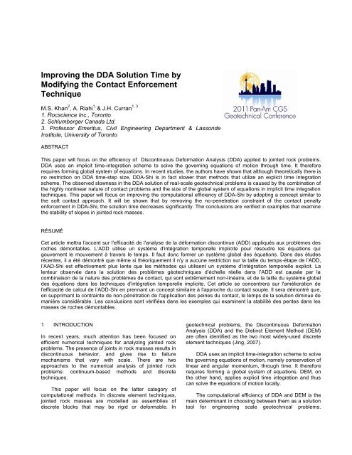
disadvantages to this approach; one is related to thepenalty value and the second to satisfying the nopenetrationconstraint.The penalty value can significantly affect thecomputational efficiency of DDA (refer to Khan, 2010,Chapter 3). An inappropriate penalty value may destroythe conditioning of the global stiffness matrix, thusaffecting the convergence of the solution. In addition, it isdifficult to estimate an appropriate penalty value for anarbitrary problem. Alternative approaches such as theclassical Lagrange multiplier method and the augmentedLagrange method also have some disadvantages. Theclassical Lagrange multiplier method adds a gapparameter for each contact, creating a larger system ofequations and the augmented Lagrange method requiresmore iterations to reach convergence, increasing thesolution time and consequently, the computational cost.In DDA-Shi, the no-penetration contact constraint isimposed at each contact point. To satisfy this constraint,the iterative solver proceeds until there is no penetrationat any contact point. Achieving zero-penetration isimpractical. In order to avoid this problem, Shi defined apenetration control parameter or penetration tolerance (f 0).Contact convergence and the final solution largely dependon the value of f 0. Very small tolerance values can lead tofluctuation of results or even divergence of the solution,and large tolerance values may produce incorrect contactforces. In addition, it is difficult to determine an acceptabletolerance value for an arbitrary problem.In addition, satisfying the no-penetration constraint atevery contact point is a time-consuming process becauseof the need to form and solve a large system of equationsusing an iterative process. The no-penetration approachmay exhibit fluctuating divergence for problems involvinglarge numbers of blocks or contact points (Khan, 2010,Chapter 3). It has been shown that the number of opencloseiterations required for contact convergence in eachtime step dramatically increases for problems involvingmore than 500 blocks. As the number of open-closeiterations increases the computational cost also increases.These aforementioned disadvantages make DDA’shard contact approach computationally expensive.Moreover, the assumption that contacts are infinitely rigidis unrealistic because blocks undergo some localdeformation at contact points that must be accounted for.In this work, we adopted the concept of soft contact byallowing interpenetration or overlapping of the contactingblocks (DDA-SC). To do so, a normal contact spring withfinite stiffness is used to represent the measurablestiffness at a contact point (see Fig. 1) Details ofimplementation are discussed in (Khan, 2010).Although physically, overlapping andinterpenetrations of blocks do not occur, small numericalinterpenetration can be interpreted as the actual surfacedeformation at contact points. The joint stiffnessproperties can be obtained from laboratory and fieldtesting.Figure 1. Contact representation in DDA-SC3 EXAMPLESIn this section, the improvements in the computationalefficiency of DDA-SC over DDA-Shi are demonstratedthrough four examples. The examples involve simple caseof block sliding as well as large scale slope stabilityproblems.3.1 Block on an Inclined SurfaceThe benchmark example involves a rigid block sliding onan inclined plane (Fig. 2). The unit depth rectangular blockhas a length 2.0 m and height 1.0 m, and lies on aninclined surface with a slope angle, . The friction anglebetween the block and the inclined surface is specifiedthrough the joint friction angle, . The aspect ratio of theblock and orientation were chosen such that the mode offailure is sliding. Due to gravitational forces, the block onthe inclined plane will accelerate down the plane. In DDA-SC model, normal and shear contact spring stiffness, k nand k s, equal to 50 MPa/m are used.The analytical solution for the displacement, d, of theblock centroid relative to its at-rest position is given by 0displacement ( d) 1 g (sin cos tan ) 2 2 t Using DDA-SC, for five different cases that involve arange of friction angles and a slope angle of 30°, the blockcentroid displacement is computed. The solution iscompared to that obtained from DDA-Shi.The block centroid displacement as a function oftime is shown in Fig. 3. It is observed that DDA-SCcaptures an essential aspect of problem behavior in thesliding process: namely, the displacement reduces as thefriction angle increases. Fig. 4 shows the residual error,Anal DDAe d d , with respect to time. It can be interpretedform this figure that DDA’s solution error grows linearly intime. Although for both the soft and the hard contactapproaches the error is linear with respect to time, thehard contact approach solution deviates more from the(8)
Residual error (m)Displacement (m)analytical solution. DDA-Shi has an error less than 2% forthis problem whereas the DDA-SC exhibits an error lessthan 1%. It can therefore be concluded that the softcontact approach has improved the accuracy of DDA.slope to failure. For the detailed procedure of theimplementation of the SSR technique in DDA, refer to(Khan, 2010).Fig. 6 demonstrates the displacement vs. ShearReduction Factor (SRF) for a selected point on the block.The displacements are obtained at 1000 time step. Theresults indicate the SRF that brings DDA-SC solution ofthis example to instability is 1.829. The prediction is ingood agreement with the analytical solution of 1.835.Figure 2. Block sliding on inclined surface (problemgeometry)Block on inclined surface3.002.502.00Figure 3. Block sliding on inclined surface (displacementvs. time)0.0140.0120.0100.0080.0060.0040.0020.000DDA-SC Analytical1.50 =20°1.00 =25°0.50 =29.9°0.000 0.2 0.4 0.6 0.8 1 1.2DDA-SCTime (sec.)DDA-Shi0 1 2 3 4 5Time (sec.)Figure 4. Residual error in displacement using DDA-SCand DDA-Shi3.2 Plane Failure Slope StabilityThis example intends to show the accuracy and reliabilityof the enhanced DDA solution in a simple slope stabilityexample exhibiting planar failure. The problem geometry isdepicted in Fig. 5. The slope has a height of 60 meters, aslope face angle, , of 50°, and joint failure plane dippingat 35°. The block and joint material properties are listed inTable 1. The joint exhibits Mohr-Coulomb elasto-plasticbehavior. The analytical solution for the stable state canbe obtained by comparing the driving forces and theresisting forces developed along the joint.In order to compute the Factor of Safety (FOS), theShear Strength Reduction (SSR) procedure (Diederichs etal., 2007; Hammah et. al., 2004) is implemented in DDA-SC. SSR is a simple approach that involves a systematicsearch for a strength reduction factor (SRF) that brings a =0° =10°Figure 5. Plane failure slope stability geometry1.50E+001.00E+005.00E-01Factor of Safety0.00E+001.8 1.805 1.81 1.815 1.82 1.825 1.83 1.835 1.84Figure 6. Displacement of measured point vs. SRF usingDDA-SCTable 1. Input parameters used in DDA-SCMaterial propertiesUnit weight, = 0.027 MN/m 3Joint friction angle, = 40°Joint cohesion, c = 0.1 MN/m 2Tensile strength, t = 0DDA-SC parametersk n = 1 GPa/m and k s = 0.1 GPa/mTime step, ∆t = 0.001 umax = 1E-05 mGravity, g = 10 m/sec 23.3 Plane Failure Slope Stability Involving MultipleBlocksThis problem involves a slope with a parallel set of jointsspaced 10 m apart dipping out of the slope at 35.2°(Fig. 7)The slope has a height of 260 m and a slope face angle,, of 55°. Parallel joints split the rock mass into 28discrete blocks, which are considered to be rigid. Thematerial properties are listed in Table 2.SRF
This example intends to show how well DDA-SC canhandle problems with multiple blocks. For comparisonpurposes, a UDEC analysis was performed. The inputparameters used in DDA-SC and UDEC are listed in Table2.The closed-form solution for this problem (Khan,2010) gives a factor of safety of 1.3092. The UDECanalysis predicts a factor of safety, 1.3, and a planarfailure mechanism that involves sliding along a joint nearthe slope toe (see Fig. 7). The DDA-SC analysis predictsthe factor of safety to be 1.296. Comparison of resultsconfirms that that DDA-SC can predict the mechanism ofdeformation and failure correctly and within the desirablelevel of accuracy.to reach equilibrium state. The equilibrium condition isconsidered to be achieved when the unbalanced force isless than a specified tolerance within a specified numberof time steps. For this problem, the limiting unbalancedforce was set to be 1.0 kN and the limiting number of timesteps was set to be 10000.(a)(b)(c)(d)Figure 8. Slope stability simulation in DA-SC (a) Step= 1 (initial geometry), (b) Step = 1522 (failure initiates), (c)Step = 3300 (block sliding) (d) Step = 9100 (block slidingand rotation)Table 3. Input data used for verification Example 3.4Figure 7. Planar failure slope example (multiple blocks)Table 2. Input data used for verification Example 3.3Material propertiesUnit weight, = 0.0261 MN/m 3Joint friction angle, = 40°Joint cohesion, c = 0.1 MN/m 2Tensile strength, t = 0Gravity, g = 10 m/sec 2DEM input parametersk n = 1 GPa/mk s = 1 GPa/mTime step, ∆t = 0.000873DDA-SC input parametersk n = 1 GPa/mk s = 1 GPa/mTime step, ∆t = 0.001u max = 1E-05 m3.4 Slope Stability Involving Two Joint SetsA slope with a height of 260 m and a slope face angle of55° is considered. It has two sets of intersecting joints, aset of horizontal joints with 40 m spacing and a set parallelto the slope face with 10 m spacing as shown in Fig. 8.This slope stability problem was analyzed by DDA-SC andUDEC. Block material properties and input parametersused in the DDA-SC and UDEC analyses are given inTable 3.The constitutive behavior of the joints follows a Mohr-Coulomb failure criterion. The SSR procedure is used toestimate the factor of safety. Using UDEC, initially, thesteady state or equilibrium state of the problem isachieved, and subsequently, the Mohr-Coulomb strengthparameters are repeatedly reduced until the analysis failsMaterial propertiesUnit weight, = 0.0261 MN/m 3Joint friction angle, = 40°Joint cohesion, c = 0.1 MN/m 2Tensile strength, t = 0Gravity, g = 10 m/sec 2UDEC input parametersk n = 10 GPa/mk s = 10 GPa/mTime step, ∆t = 0.0069Damping = auto dampingoption usedDDA-SC input parametersk n = 10 GPa/mk s = 10 GPa/mTime step, ∆t = 0.001u max = 1E-05 mIn DDA-SC, the input parameter for relativemaximum displacement is used to judge the limitequilibrium state (Shi, 2007). When the relative maximumdisplacement is less than the specified tolerance, thesystem is assumed to have attained steady state. Asmentioned before, to compute the factor of safety usingSSR method, a separate function is incorporated into theexisting DDA code. Similar to the UDEC methodology, theDDA analysis is first run until steady state is attained andthen the shear strength parameters are systematicallyreduced until it does not attain steady state within aprescribed maximum number of time steps. The maximumnumber of time steps is set to be twice the number of timesteps required to attain steady state in the beginning ofthe analysis.Fig. 8 illustrates the DDA-SC analysis of this problemat various critical states during the analysis. The time-stepsize used for the analysis was 0.001 second. At timestep=1522 failure is initiated by sliding of a block at the toe
CPU time (min.)of the slope. DDA-SC predicts a failure mechanism whichis initiated by sliding and then by rotation of the blocknearest to the slope toe. DDA-SC predicted a factor ofsafety of 1.82. The failure mechanism predicted by DDA-SC is shown in Fig. 9(a). The UDEC analysis predicted asimilar failure mechanism, and a factor of safety of 1.74shown in Fig. 9(b). The difference between the factors ofsafety predicted by DDA-SC and UDEC is approximately3.5%.(a)(b)Figure 9. Comparison of slope failure mechanism in DDA-SC and DEM (a) Slope failure predicted by DDA-SC (b)Slope failure predicted by UDECFor comparison purposes, this slope problem wasalso analyzed by DDA-Shi, which predicts a similar failuremechanism and a factor of safety of 1.80. The final resultsobtained by UDEC, DDA-Shi and DDA-SC are provided inTable 4. Comparison of results confirms that hard contactand soft contact logics used in enforcement of contactconstraints lead to convergence to one physicallyadmissible solution. In terms of computational speed,DDA-Shi took approximately 25 minutes of CPU time toattain limit equilibrium state whereas DDA-SC tookapproximately 6 minutes (refer to Table 4). Resultsindicate that soft contact implementation improved thecomputational efficiency of DDA. DDA-SC, however, couldnot match the speed of DEM which reached equilibrium inless than one minute.Table 4. Comparison of results from DDA and UDEC forExample 3.4AspectDDA- DDA-Shi SCUDECProblem Blocks 482 482 468size DOFs 1446 1446 1404AnalysisresultFailuremechanismBlockslidingandrotationBlockslidingandrotationBlockslidingandrotationFactor ofsafety1.80 1.82 1.74Steady25 6 1CPU time(min.)statePost failure10 m 47.3 10.4 2.820 m 65.4 17.8 4.330 m 78.7 25.3 5.740 m 98.2 29.6 7.2Average25 m 72.4 20.8 5.0It has been discussed that application of discreteelement techniques is most desired when largedeformation, including sliding or rotation of blocks are adominant mechanism in the response. Therefore, thecapability and efficiency of discrete element methods inthe post-failure regime is an integral part of the evaluationof discrete methods. The efficiency of the DDA solution inthe post-failure regime is investigated by recording theCPU time for four different “physical times” (see Table 4).The times associate with a block displacement of 10 m, 20m, 30 m, and 40 m.The displacement versus CPU time for DDA-SC,UDEC, and DDA-Shi solutions are plotted in Fig. 10. Thisfigure shows that compared to DDA-Shi, DDA-SC hasimproved the computational speed by a factor of four inmodelling the post-failure behaviour. However, UDEC,which is based on the distinct element method, took anaverage of 5 minutes, i.e., four times faster than DDA-SCand 15 times faster than DDA-Shi.Post-failure analysisUDEC DDA-SC DDA-Shi1201008060402000 10 20 30 40 50Displacement (m)Figure 10. Comparison of time taken for post-failureanalysis in Example 3.4It has been shown by Khan et al. (2010) that for rigidblocks, DEM and DDA differ in their time integrationscheme and their contact enforcement method. It can beargued that after incorporating the soft contact approachin DDA, the main difference between DEM and DDA-SC isthe time integration scheme used, implicit versus explicit.Implicit time integration schemes require assembly of aglobal matrix to solve a coupled system of equations.Explicit time integration scheme leads to an uncoupledsystem of equations, which can be solved for each degreeof freedom of a problem separately.DDA requires that at each time step, a system ofequations in the form of Equation (5) be solved iteratively.At each iteration of the solution, the global stiffness matrixis updated based on the updated position of block, andthe position of the blocks is obtained by finding thesolution to Equation (5). DDA-SC, therefore requires thatthe stiffness terms arising from contacting objects beincorporated in the global stiffness matrix. Any change incontact state results in nonlinear behaviour and changesin the global stiffness matrix. It is therefore expected thatin systems where a large number of contacts are breakingand forming, multiple matrix inversions will be requiredduring each time step.During the post-failure state, new contacts arecontinuously forming and old contacts are breaking. Thisbehaviour triggers continuous changes in the globalstiffness matrix, and thus leads to slow convergence of the
solution. Slow convergence increases the computationalcost.4 CONCLUSIONThe hard contact approach used in DDA-Shi assumescontacts are rigid and does not allow penetration at thecontact points. For this reason, overlap or interpenetrationof the blocks is prevented using penalty springs and thecontact convergence is achieved iteratively. There are twomajor disadvantages of this approach; one is related tothe penalty value and the second to satisfying the nopenetrationconstraint.This paper focused on improving the computationalefficiency of DDA-Shi by adopting a concept similar to thesoft contact approach used in UDEC. To implement a softcontact, the no-penetration constraint of the contactpenalty enforcement was removed. In order to preventlarge penetration of contacting objects, the time step sizehowever was controlled. It was shown that suchmodification reduces the solution time significantly. Theconclusions are verified in examples that examine thestability of slopes in jointed rock masses.Shi, G.H. 1993. Block system modeling by discontinuousdeformation analysis, Computation Mechanics,Southampton, UK.Shi, G.H. 2007. Application of Discontinuous DeformationAnalysis (DDA) to rock stability analysis, Proceedingsof 8th international conference on analysis ofdiscontinuous deformation – Fundamentals &Application to mining and civil engineering (ICADD-8),Beijing, China.Shi, G.H. 1988. Discontinuous Deformation Analysis,Ph.D. thesis, University of California, Berkeley, USA.Wang, C.Y., Chuang, C.C., Sheng, J. 1996. Timeintegration theories for the DDA method with finiteelement meshes, Proceedings of 1st Int. Forum onDiscontinuous Deformation Analysis (DDA) andSimulations of Discontinuous Media, TSI, Berkeley,CA, USA. 263–287,Wriggers, P. 2002. Computational contact mechanics,John Wiley & Sons, Hoboken, NJ, USA.REFERENCESDiederichs, M. S., Lato, M., Hammah, R. and Quinn, P.2007. Shear Strength Reduction Approach for SlopeStability Analyses, Invited paper, 1st Canada-USRock Mechanics Symposium, Vancouver, BC.Hammah, R.E., Curran, J.H.,,Yacoub, T.E.,, and Corkum,B. 2004. Stability analysis of rock slopes using theFinite Element Method, Proceedings of the ISRMRegional Symposium EUROCK 2004 and the 53 rdGeomechanics Colloquy, Salzburg, Austria.Itasca Consulting Group. 2004. UDEC - Universal DistinctElement Code, Version 4.0 - User’s Manual,Minneapolis, MN, USA.Jing, L., Stephanson, O. 2007. Fundamentals of discreteelement methods for rock engineering - Theory andApplications, Developments in GeotechnicalEngineering, Elsevier, 85.Khan, M.S. 2010. Investigation of discontinuousdeformation analysis for application in jointed rockmasses, Ph.D. Dissertation, University of Toronto.Khan, M.S, Riahi, A., Curran, J.H., Effects of time stepsize on the efficiency of Discontinuous DeformationAnalysis in jointed rock problems, Proceedings of the2010 ISRM Symposium and 6th Asian RockMechanics Symposium, New Delhi, India, 2010.Koo, C.Y., Chern, J.C. 1998. Modification of the DDAmethod for rigid block problems, International Journalof Rock Mechanics and Mining Sciences, 35(6):684–693.Mohammadi, S. 2003. Discontinuum mechanics: UsingFinite and Discrete Elements, WIT Press,Southhampton, UK.Riahi, A., Curran, J.H., Hamma, R. 2010. Limits ofapplicability of the finite element explicit joint model inthe analysis of jointed rock problems, Proceedings ofthe 44 th ARMA Conference, Salt Lake City, UT, USA.