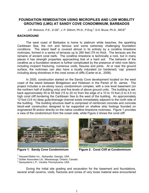
Foundation Remediation using Micropiles and LMG Grouting at ...
Foundation Remediation using Micropiles and LMG Grouting at ...
Foundation Remediation using Micropiles and LMG Grouting at ...

You also want an ePaper? Increase the reach of your titles
YUMPU automatically turns print PDFs into web optimized ePapers that Google loves.
3mass near sea level along prominent sub-horizontal weaknesses combined with subverticalmajor fissures extending l<strong>and</strong>ward from the sea to below <strong>and</strong> beyond the building.Figure 3: Borehole Camera<strong>at</strong> 13 foot depthFigure 4: 1 meter high Cavediscovered under StructureThe distress cracking in the building appeared on all five levels of the main floors ofthe building (Level 1 to 5) <strong>and</strong> also in the basement (Level 0). The majority of the crackingwas concentr<strong>at</strong>ed in the northwest corner of the building, principally in the basement <strong>and</strong> onthe first three floors. However, cracking was also observed (albeit less severe) in thesouthwest corner <strong>and</strong> on the west central side <strong>and</strong> in the northeast corner of the building.In general the cracking typically comprised about 45° oriented flexural shear cracking onboth east-west <strong>and</strong> north-south structural walls, however some sub-vertical (about 90°)tensile cracking was also observed. Figure 5 shows a map of some of the exterior cracksobserved on the structure. Figure 6 is a photograph of typical interior cracking.Figure 5: Cracking on Exterior of BuildingFigure 6: Interior CrackingNumerical analysis (continuum, FLAC, <strong>and</strong> discrete element analysis-UDEC) wascarried out on two sections through the northwest of the building to provide insight into thepotential mechanisms th<strong>at</strong> resulted in the observed crack p<strong>at</strong>terns in the structure walls.Various vertical zones of weakness along the observed p<strong>at</strong>tern of sub-vertical jointing
5Figure 8: Interpreted Crack P<strong>at</strong>terns which M<strong>at</strong>ched Observed CrackingREMEDIATION CONCEPTS AND DESIGNConsidering the subsurface conditions <strong>at</strong> the site <strong>and</strong> the fact th<strong>at</strong> any found<strong>at</strong>ionremedi<strong>at</strong>ion would have to be constructed from within <strong>and</strong> around the existing building, acombin<strong>at</strong>ion of micropiles <strong>and</strong> grouting was conceived as a probable solution. As such, inMarch 2007, Geosystems L.P. was asked to join the consultant team to provide expertiseon micropiles <strong>and</strong> grouting to refine the remedi<strong>at</strong>ion design <strong>and</strong> to guide contractorselection for the project.Given the mechanisms believed to be ca<strong>using</strong> the building movement, the remedi<strong>at</strong>ion wasconceptualized to comprise three main components:(i)(ii)(iii)cre<strong>at</strong>ion of a barrier (i.e. a buried, sub-surface seawall/grouted curtain) to preventfurther marine intervention/energy influx into the subsurface zone bene<strong>at</strong>h thebuilding;provision of additional direct support to the found<strong>at</strong>ion on three sides of the perimeterof the building; <strong>and</strong>improvement of the load-bearing capacity of the existing weak coralline subsurfacestr<strong>at</strong>a below the interior of the northern half of building.The subsurface seawall was designed to be comprised of two rows of 5 1/2 inch (140mm) diameter micropiles. The outer row of near vertical micropiles was designed on a 15degree inclin<strong>at</strong>ion from the vertical, parallel to the sides of the building <strong>and</strong> extended downinto the more competent coralline rock <strong>at</strong> a depth of 50 foot (15 m). The inner row of
7CONTRACTOR SELECTIONFigure 9: New Grade Beam around <strong>Found<strong>at</strong>ion</strong>Given the need to have the remedi<strong>at</strong>ion largely completed before the onset of thehurricane season, the overall schedule was extremely compressed. This meant th<strong>at</strong> thesite assessment <strong>and</strong> preliminary remedial design had to progress during the same periodwhen the contractor was selected, <strong>and</strong> a fast mobiliz<strong>at</strong>ion to the isl<strong>and</strong> was required.Furthermore, the precise scope of the remedi<strong>at</strong>ion, <strong>and</strong> the selection of the mostappropri<strong>at</strong>e means <strong>and</strong> methods could only be determined when the work got underway,given the need to implement the remedi<strong>at</strong>ion in a responsive fashion while observing thefound<strong>at</strong>ion <strong>and</strong> the structure itself. This meant th<strong>at</strong> the contractor's expertise <strong>and</strong>experience would be invaluable as an integral part of engineering the solution in real time<strong>and</strong> <strong>at</strong> all times on this project such input was sought, <strong>and</strong> given. Overall, the fast trackn<strong>at</strong>ure of the work would tend to place severe interpersonal strains between the respectivegroups of personalities represented on site, including several sets of specialist consultants,a general contractor, the specialty found<strong>at</strong>ion/grouting subcontractor, the projectmanagement team <strong>and</strong>, of course, the owner himself. Such a combin<strong>at</strong>ion of factorsstrongly favors the cre<strong>at</strong>ion of an ‘Alliance,’ (Carter <strong>and</strong> Bruce, 2005) <strong>and</strong> <strong>at</strong> the S<strong>and</strong>yCove project, key elements of alliancing were implemented to assure selection of thecorrect specialty contractor, <strong>and</strong> to maintain excellent communic<strong>at</strong>ions, problem resolutionmechanisms, compliance to schedule, <strong>and</strong> cost management structures throughout theproject dur<strong>at</strong>ion.
9Figure 12: Tension Test Result from 74 foot long <strong>LMG</strong> Micropile (60 ft free length)Monitoring During <strong>and</strong> Following ConstructionDuring the course of the remedi<strong>at</strong>ion work, the conditions encountered during drilling<strong>and</strong> the volume of grout injected (or ‘take’) <strong>at</strong> discrete depth intervals in each hole wascarefully recorded. In this manner, the geological model developed as part of the designphase <strong>and</strong> formul<strong>at</strong>ed into the numerical modelling was adjusted <strong>and</strong> refined asconstruction proceeded. Refinements to the design <strong>and</strong> borehole layouts were undertakenin near real-time as additional subsurface inform<strong>at</strong>ion was obtained during the construction.Records were upd<strong>at</strong>ed daily <strong>and</strong> the grout-take d<strong>at</strong>a was tracked <strong>using</strong> 2-D <strong>and</strong> 3-Dgraphical models so th<strong>at</strong> the weakest conditions (i.e. most voided) in the subsurface couldbe readily identified. Figure 13 shows the 3-D model, where higher grout take volumes areshown with larger spheres. These areas were then targeted with additional grout-onlyholes during the course of the production work. At the completion of the works, d<strong>at</strong>a hadbeen acquired from the drilling <strong>and</strong> grouting of 174 micropiles, during which 1000 yd 3 (750m 3 ) of low-mobility grout was injected into the voided areas of the found<strong>at</strong>ion around theperimeter <strong>and</strong> below the interior of the building.In addition to documenting the drilling <strong>and</strong> grout-takes during the remedi<strong>at</strong>ion, thebuilding was regularly monitored for settlement or heave, tilt <strong>and</strong> crack propag<strong>at</strong>ionthroughout the period of construction <strong>and</strong> after completion. The building monitoringinstrument<strong>at</strong>ion included a suite of electro-levels, tilt meters, crack gauges, precise levelingpoints <strong>and</strong> prisms. The instrument<strong>at</strong>ion d<strong>at</strong>a showed the building responding to theconstruction by initial downward (i.e. settlement) movement as a result of the disturbance tothe weak soils during drilling <strong>and</strong> flushing for the micropiling oper<strong>at</strong>ions followed by upward(i.e. heave) movement as a result of the pressure grouting. In general a trend of increasingstabiliz<strong>at</strong>ion was observed in the instrument<strong>at</strong>ion throughout the remedi<strong>at</strong>ion program, aseach area of the building was underpinned <strong>and</strong> grouted.
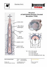
10Figure 13: 3-Dimensional Illustr<strong>at</strong>ion of Grout Loc<strong>at</strong>ions <strong>and</strong> QuantitiesThe robustness of the remedi<strong>at</strong>ion fix has been tested by both marine <strong>and</strong> nonmarinedynamic stresses. During the one year post-construction monitoring period, heavyseas with recorded offshore wave heights equal to or even gre<strong>at</strong>er than those recordedduring the periods of the original crack initi<strong>at</strong>ion occurred. In addition, the structure wassubjected to a magnitude 7.4 earthquake (which occurred in the eastern Caribbean with anepicenter just north of Martinique on November 29, 2007). It was estim<strong>at</strong>ed th<strong>at</strong> the quakemeasured about magnitude 3.0 in Barbados (www.caribbean360.com). There was nosettlement or crack development as a result of these events.CONCLUSIONSThe remedi<strong>at</strong>ion <strong>and</strong> improvement of the building found<strong>at</strong>ion ultim<strong>at</strong>ely included thefollowing works: Install<strong>at</strong>ion of a 290 foot (88 m) long sub-surface ‘sea-wall’ barrier/grouted cut-offcurtain around three sides of the building; Direct support by 137 – approxim<strong>at</strong>ely 70 feet long (21 m), 5 1/2 inch (140 mm)diameter micropiles underpinning the edges of three sides of the building (north, south<strong>and</strong> west); Indirect support by 37 – approxim<strong>at</strong>ely 65 feet (20 m) long, 5 1/2 inch (140 mm)diameter micropiles installed along heavily loaded walls below the interior of thenorthern portion of the building; <strong>and</strong> <strong>Grouting</strong> of voids <strong>and</strong> interconnected fissures/fractures in the subsurface below thebuilding.