ABS MK II - VWClub.BG
ABS MK II - VWClub.BG
ABS MK II - VWClub.BG

You also want an ePaper? Increase the reach of your titles
YUMPU automatically turns print PDFs into web optimized ePapers that Google loves.
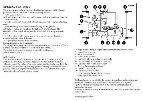
Either the accumulator pressure or the brake-fluid level is too low if bothwarning lamps light simultaneously.If the brake warning lamp lights, the conventional brake system is first to bechecked and repaired if necessary.SELF-DIAGNOSISEach flashing code is initiated by way of a start pulse (lamp on) with durationof approx. 2,5 s. The individual positions are separated in each case by aninterval (lamp off) of approx. 2,5 s.Only the short flashing pulses are to be counted. The flashing code isconstantly repeated. The next flashing code is not output until the button ispressed for approx. 3 s.See picture: flashing code 1234.Priority 1 faults are output first and halt further flashing-code output. Eliminatefault and stimulate again.Flashing code output:- Lever gear-lever boot off center console.- Connect KDAW 9975; see picture.Note: The sequence of connectors (picture) does not have to coincide with thatin the vehicle.Black plug (A) with bevel at top on both sides is always voltage supply.Blue/white plug (B) beveled on side at top and bottom is stimulation lead (B/1).Note: If the flashing code is not output, determine the correct diagnosis plugfrom controller plug term. 26.- Press button.- Switch on ignition.- <strong>ABS</strong> warning lamp lights.- Release button after approx. 3 s.- Flashing code is flashed up by way of <strong>ABS</strong> warning lamp and constantlyrepeated.- Read out entire fault memory and note down each individual flashing code.The fault memory has been completely read out when the warning lamp flashescontinuously and uniformly in 2,5 second cycle (flashing code 0000).A test drive is to be performed after repairing the <strong>ABS</strong> system. In doing so,drive for at least 1 minute at a speed in excess of 40 km/h.Note: Remove all diagnosis leads when performing test drive.
Note:Fault memory is automatically cancelled during test drive. The only faults to becancelled are those, which have previously been read out at least once.Read out fault memory again. If flashing code 4444 is output, there are nofurther faults stored in the <strong>ABS</strong> controller. If no flashing code is output or theflashing code is not listed in the table, refer to component/functional test.Test instructions:Do not use test prods for measurements at all equipment plugs, but rather makeuse of suitable test plugs from Bosch test cable set 1 687 011 208 as otherwisecontacts could be damaged.SELF-DIAGNOSIS FLASHING CODE TABLE0000 End of output/controllerEND OF OUTPUT/controller- Remove all diagnosis leads.- Following repair, perform test drive for at least 1 min. at a speed in excess of40 km/h.- Repeat self-diagnosis.1111 ControllerSELF-DIAGNOSIS FLASHING CODE 1111Controller- Check all fuses.- Ignition off.- Pull plug off controller.- Check ground connections at controller plug. X1 term. 1, 11 -> body groundSet value: < 0,5 Ohm- Ignition on and start engine.- Check voltage supply at controller plug. X1 term. 2 -> body groundSet value: 11...15 V- Controller defective.1112 Inlet valve VLSELF-DIAGNOSIS FLASHING CODE 1112Inlet valve, front left- Ignition off.- Pull plug off controller.- Check solenoid valve resistance at controller plug. X1 term. 11 -> X1 term.35Set value: 5...7 Ohm- Check solenoid valves and leads for short to ground/short to positive, opencircuit and loose contacts as per circuit diagram.- Check contacts of connectors.SELF-DIAGNOSIS FLASHING CODE 1112...1222- Remove solenoid valve relay.- Check function of valve relay.- Check ground connection, valve relay. K1 term. 87a -> body ground Setvalue: < 0,5 Ohm- Check voltage supply, valve relay. K1 term. 87 -> body groundSet value: 10...15 V- Check lead from valve relay to controller plug. K1 term. 30 -> X1 term. 3, 20- Controller defective.1114 Inlet valve VRSELF-DIAGNOSIS FLASHING CODE 1114Inlet valve, front right- Ignition off.- Pull plug off controller.- Check solenoid valve resistance at controller plug.X1 term. 11 -> X1 term. 15Set value: 5...7 Ohm- Check solenoid valves and leads for short to ground/short to positive, opencircuit and loose contacts as per circuit diagram.- Check contacts of connectors.SELF-DIAGNOSIS FLASHING CODE 1112...1222- Remove solenoid valve relay.- Check function of valve relay.- Check ground connection, valve relay. K1 term. 87a -> body groundSet value: < 0,5 Ohm- Check voltage supply, valve relay. K1 term. 87 -> body groundSet value: 10...15 V- Check lead from valve relay to controller plug. K1 term. 30 -> X1 term. 3, 20- Controller defective.1122 Inlet valve HASELF-DIAGNOSIS FLASHING CODE 1122Inlet valve, rear
- Ignition off.- Pull plug off controller.- Check solenoid valve resistance at controller plug. X1 term. 11 -> X1 term.17Set value: 5...7 Ohm- Check solenoid valves and leads for short to ground/short to positive, opencircuit and loose contacts as per circuit diagram.- Check contacts of connectors.SELF-DIAGNOSIS FLASHING CODE 1112...1222- Remove solenoid valve relay.- Check function of valve relay.- Check ground connection, valve relay. K1 term. 87a -> body groundSet value: < 0,5 Ohm- Check voltage supply, valve relay. K1 term. 87 -> body groundSet value: 10...15 V- Check lead from valve relay to controller plug. K1 term. 30 -> X1 term. 3, 20- Controller defective.1132 Outlet valve VLSELF-DIAGNOSIS FLASHING CODE 1132Outlet valve, front left- Ignition off.- Pull plug off controller.- Check solenoid valve resistance at controller plug. X1 term. 11 -> X1 term.16Set value: 3...5 Ohm- Check solenoid valves and leads for short to ground/short to positive, opencircuit and loose contacts as per circuit diagram.- Check contacts of connectors.SELF-DIAGNOSIS FLASHING CODE 1112...1222- Remove solenoid valve relay.- Check function of valve relay.- Check ground connection, valve relay. K1 term. 87a -> body groundSet value: < 0,5 Ohm- Check voltage supply, valve relay. K1 term. 87 -> body groundSet value: 10...15 V- Check lead from valve relay to controller plug. K1 term. 30 -> X1 term. 3, 20- Controller defective.1134 Outlet valve VRSELF-DIAGNOSIS FLASHING CODE 1134Outlet valve, front right- Ignition off.- Pull plug off controller.- Check solenoid valve resistance at controller plug. X1 term. 11 -> X1 term.34Set value: 3...5 Ohm- Check solenoid valves and leads for short to ground/short to positive, opencircuit and loose contacts as per circuit diagram.- Check contacts of connectors.SELF-DIAGNOSIS FLASHING CODE 1112...1222- Remove solenoid valve relay.- Check function of valve relay.- Check ground connection, valve relay. K1 term. 87a -> body groundSet value: < 0,5 Ohm- Check voltage supply, valve relay. K1 term. 87 -> body groundSet value: 10...15 V- Check lead from valve relay to controller plug. K1 term. 30 -> X1 term. 3, 20- Controller defective.1142 Outlet valve HASELF-DIAGNOSIS FLASHING CODE 1142Outlet valve, rear- Ignition off.- Pull plug off controller.- Check solenoid valve resistance at controller plug. X1 term. 11 -> X1 term.33Set value: 3...5 Ohm- Check solenoid valves and leads for short to ground/short to positive, opencircuit and loose contacts as per circuit diagram.- Check contacts of connectors.SELF-DIAGNOSIS FLASHING CODE 1112...1222- Remove solenoid valve relay.- Check function of valve relay.- Check ground connection, valve relay. K1 term. 87a -> body groundSet value: < 0,5 Ohm- Check voltage supply, valve relay. K1 term. 87 -> body groundSet value: 10...15 V
- Check lead from valve relay to controller plug. K1 term. 30 -> X1 term. 3, 20- Controller defective.1222 Main valveSELF-DIAGNOSIS FLASHING CODE 1222Main valve,- Ignition off.- Pull plug off controller.- Check solenoid valve resistance at controller plug. X1 term. 11 -> X1 term.18Set value: 2...5 Ohm- Check solenoid valves and leads for short to ground/short to positive, opencircuit and loose contacts as per circuit diagram.- Check contacts of connectors.SELF-DIAGNOSIS FLASHING CODE 1112...1222- Remove solenoid valve relay.- Check function of valve relay.- Check ground connection, valve relay. K1 term. 87a -> body groundSet value: < 0,5 Ohm- Check voltage supply, valve relay. K1 term. 87 -> body groundSet value: 10...15 V- Check lead from valve relay to controller plug. K1 term. 30 -> X1 term. 3, 20- Controller defective.1233 Wheel-speed sensor VLSELF-DIAGNOSIS FLASHING CODE 1233Wheel-speed sensor, front left- Ignition off.- Pull plug off controller.- Check wheel-speed-sensor winding resistance at controller plug. X1 term. 5 -> X1 term. 23Set value: 0,8...1,4 kOhm- Check wheel-speed sensor and leads for short to ground/short to positive,mix-up, open circuit and loose contacts at controller plug. X1 term. 5 -> X1term. 23- Check condition of connectors.- Excessive wheel bearing clearance.SELF-DIAGNOSIS FLASHING CODE 1233- Turn wheel, front left and check voltage at controller plug (alternatingvoltage). X1 term. 5 -> X1 term. 23Set value: > 75 mV- Wheel-speed sensor loose or not flat on mount.- Ring gear defective (e.g. corroded, dirty, damaged or loose).- Check number of teeth.Set value: 43- Controller defective.1241 Wheel-speed sensor VRSELF-DIAGNOSIS FLASHING CODE 1241Wheel-speed sensor, front right- Ignition off.- Pull plug off controller.- Check wheel-speed-sensor winding resistance at controller plug. X1 term. 7 -> X1 term. 25Set value: 0,8...1,4 kOhm- Check wheel-speed sensor and leads for short to ground/short to positive,mix-up, open circuit and loose contacts at controller plug. X1 term. 7 -> X1term. 25- Check condition of connectors.- Excessive wheel bearing clearance.SELF-DIAGNOSIS FLASHING CODE 1241- Turn wheel, front right and check voltage at controller plug (alternatingvoltage). X1 term. 7 -> X1 term. 25Set value: > 75 mV- Wheel-speed sensor loose or not flat on mount.- Ring gear defective (e.g. corroded, dirty, damaged or loose).- Check number of teeth.Set value: 43- Controller defective.1243 Wheel-speed sensor HRSELF-DIAGNOSIS FLASHING CODE 1243Wheel-speed sensor, rear right- Pull plug off controller.- Check wheel-speed-sensor winding resistance at controller plug. X1 term. 4 -> X1 term. 22Set value: 0,8...1,4 kOhm
- Check wheel-speed sensor and leads for short to ground/short to positive,mix-up, open circuit and loose contacts at controller plug. X1 term. 4 -> X1term. 22- Check condition of connectors.- Excessive wheel bearing clearance.SELF-DIAGNOSIS FLASHING CODE 1243- Turn wheel, rear right and check voltage at controller plug (alternatingvoltage). X1 term. 4 -> X1 term. 22Set value: > 75 mV- Wheel-speed sensor loose or not flat on mount.- Ring gear defective (e.g. corroded, dirty, damaged or loose).- Check number of teeth.Set value: 43- Controller defective.1311 Wheel-speed sensor HLSELF-DIAGNOSIS FLASHING CODE 1311Wheel-speed sensor, rear left- Ignition off.- Pull plug off controller.- Check wheel-speed-sensor winding resistance at controller plug. X1 term. 6 -> X1 term. 24Set value: 0,8...1,4 kOhm- Check wheel-speed sensor and leads for short to ground/short to positive,mix-up, open circuit and loose contacts at controller plug. X1 term. 6 -> X1term. 24- Check condition of connectors.- Excessive wheel bearing clearance.SELF-DIAGNOSIS FLASHING CODE 1311- Turn wheel, rear left and check voltage at controller plug (alternatingvoltage). X1 term. 6 -> X1 term. 24Set value: > 75 mV- Wheel-speed sensor loose or not flat on mount.- Ring gear defective (e.g. corroded, dirty, damaged or loose).- Check number of teeth.Set value: 43- Controller defective.1312 Pressure warning switch and warning contactSELF-DIAGNOSIS FLASHING CODE 1312Pressure warning switch and warning contact- Ignition off.- Detach plug from controller.- Connect up ohmmeter to controller plug term. 9 and 10. (Pressureaccumulator must be charged).Set value: < 5 Ohm- Unscrew closing cover of reservoir and move float.- The warning contact S6 (picture) opens if the float with magnet M2 is movedtowards the lower stop.Contact S5 first switches on brake warning lamp by way of magnet M1.
4444 No fault storedCOMPONENT/FUNCTIONAL TESTChecking controller voltage supply- Check all fuses.- Ignition off.- Pull plug off controller.- Check ground connections at controller plug. X1 term. 1, 11 -> body groundSet value: < 0,5 Ohm- Ignition on and start engine.- Check voltage supply at controller plug. X1 term. 2 -> body groundSet value: 11...15 V- Check leads for loose contacts.<strong>ABS</strong> warning lamp does not light or flashing codes are not output- Ignition off.- Pull off controller plug.- Check <strong>ABS</strong> bulb.- Check diode in valve relay.- Check following leads and connectors as per circuit diagram for open circuit,loose contacts, short to positive or short to ground.* Diagnosis plug connections* <strong>ABS</strong> warning-lamp leads to controller and valve relay* Ground connection, valve relayChecking stop-lamp switch- Ignition off.- Pull plug off controller.- Check voltage at controller plug:X1 term. 12 -> body ground* Brake not pressed: < 1 V* Brake pressed : > 10 V- Check stop-lamp switch.- Check leads from controller plug to stop-lamp switch and fuse.- Check brake-fluid level and top up brake fluid if necessary.- If brake warning lamp is always lit, consecutively pull off plugs atcompensating tank and pressure switch.Replace corresponding component if warning lamp goes out.- No brake warning lamp function.Check fuses.Check lamp.Use circuit diagram to check leads.Checking motor relay- Ignition off.- Pull plug off controller.- Check leads from controller plug term. 14 and 32 to hydraulic modulator plugas per circuit diagram.- Check pump motor resistance.Set value: < 1 Ohm- Check resistance of solenoid (motor relay). K2 term. 85 -> K2 term. 86Set value: 50...100 Ohm- Check diode in motor relay.- Check all ground connections.Check pressure switch, hydraulic pump and high-pressure accumulator- Check all fuses.- Ignition off.- Detach controller plug.- Press brake pedal approximately 20 times (to empty high-pressureaccumulator) until there is a noticeable increase in pedal force.- Connect up ohmmeter to controller plug term. 9 to 10.Note: Reading greater than 1 MOhm corresponds to contact open and less than5 Ohm to closed.Brake warning lamp function- Ignition on.- Release hand brake.
- Dissipate accumulator pressure.* <strong>ABS</strong> contact in pressure warning switch opens at 100...110 bar.Brake warning lamp lights.- Check lead from controller plug term. 9 to <strong>ABS</strong> warning lamp unit as percircuit diagram.Check solenoid valves for proper function and mix-up.Perform test consecutively for each individual wheel.Turn appropriate wheel by hand or drive vehicle on roller dynamometer.Only connect up inlet and outlet valve of one wheel to controller plug.- Ignition off.- Install (see picture) ATE pressure test connection, part no. 03.9305-0145.2between pressure accumulator and hydraulic modulator.- Connect up pressure gauge (250 bar).- Bleed brake system and pressure gauge.- Pressure accumulator must have been discharged.- Ignition on.* Pressure-gauge reading switches to initial pressure of pressure accumulatorSet value: 40...90 bar- Check pressure warning switch 9 at controller plug term. 10 and term. S3.* Brake warning lamp goes out and <strong>ABS</strong> contact in pressure warning switchcloses at 130...150 bar* Cut-out pressure,Set value: 170...190 bar- Dissipate accumulator pressure.* Renewed cut-in pressure,Set value: 130...150 bar* Pressure build-up time between cut-in and cut-out pressure,Set value: < 25 s- Ignition off.- Pull plug off pump motor.Ignition on.- Check <strong>ABS</strong> warning contact in closing cover of reservoir.* <strong>ABS</strong> warning contact opens if float makes contact with lower stop.Note: Switch-on duration of solenoid valves max. 10 s.Check pressure reduction, front left wheel:- Connect up button of KDAW 9975 to controller plug term. 2 to term. 35 andjumper term. 35 with 16.- Ignition on.- Press brake pedal.* Wheel blocks.- Press button.* Wheel can be turned.- Ignition off.- Disconnect button.Note: Switch-on duration of solenoid valves max. 10 s.Check pressure holding, front left wheel:- Connect up button of KDAW 9975 to controller plug term. 2 to 35.- Ignition on.- Press button.- Press brake pedal.* Wheel can be turned.- Release button.* Wheel blocks.- Ignition off.- Disconnect button.Note: Switch-on duration of solenoid valves max. 10 s.Check pressure reduction, front right wheel:- Connect up button of KDAW 9975 to controller plug term. 2 to term. 15 andjumper term. 15 with 34.
- Ignition on.- Press brake pedal.* Wheel blocks.- Press button.* Wheel can be turned.- Ignition off.- Disconnect button.Note: Switch-on duration of solenoid valves max. 10 s.Check pressure holding, front right wheel:- Connect up button of KDAW 9975 to controller plug term. 2 to 15.- Ignition on.- Press button.- Press brake pedal.* Wheel can be turned.- Release button.* Wheel blocks.- Ignition off.- Disconnect button.Note: Switch-on duration of solenoid valves max. 10 s.Check pressure reduction, rear axle:- Connect up button of KDAW 9975 to controller plug term. 2 to term. 17 andjumper term. 17 with 33.- Ignition on.- Press brake pedal.* Wheel blocks.- Press button.* Wheel can be turned.- Ignition off.- Disconnect button.Note: Switch-on duration of solenoid valves max. 10 s.Check pressure holding, rear axle:- Connect up button of KDAW 9975 to controller plug term. 2 to 17.- Ignition on.- Press button.- Press brake pedal.* Wheel can be turned.- Release button.* Wheel blocks.- Ignition off.- Disconnect button.Note: Switch-on duration of solenoid valves max. 10 s.Function, main solenoid valve:- Connect up button of KDAW 9975 to controller plug term. 2 to 18.- Ignition on.- Press brake pedal slightly.- Briefly press button several times.* Brake pedal must pulsate.- Ignition off.- Disconnect button.If set values are not attained:- Use circuit diagram to check leads for loose contact and open circuit.- Check for leaks in hydraulic connections (visual inspection).- Pull off plug at hydraulic modulator.- Check plug and spring contacts for corrosion.- Check ground connection of hydraulic modulator (both screw connections).- Check ground connection of pump motor.Check wheel-speed sensors and ring gear- Ignition off.- Detach controller plug.- Start engine.- Measure with Motortester special input at controller plug.* Wheel, front left term. 5 and 23* Wheel, front right term. 7 and 25* Wheel, rear right term. 4 and 22* Wheel, rear left term. 6 and 24Set value: Picture, sinusoidal signal1 = Wheel-speed sensor2 = Ring gear3 = Motortester oscilloscope
ADDITIONAL TEST STEPS* Specified tire size fitted?* If <strong>ABS</strong> warning lamp lights up from time to time when driving (e.g. afterswitching on loads) and goes out again automatically, check battery andvoltage supply (alternator, regulator and voltage dips).* Check tightness of ground strap between engine block and vehicle frame.* Spring contacts must be properly engaged.* All plug contacts ok?Perform test drive as final check:Drive for at least 1 min. at a speed of in excess of 40 km/h.Warning lamp must not light.- Turn corresponding wheel.If available, drive wheels on brake dynamometer (maximum speed and rockvehicle heftily).Note: The wheel-speed-sensor output signal must produce a sinusoidal curve,the amplitude and period of which change as a function of rotational speed. Theamplitude is additionally influenced by the air gap. It decreases with increasingair gap.The maximum permissible fluctuation in amplitude for all wheel-speed sensorsis 25 %.In the event of deviation, check:- Wheel-bearing clearance.- Ring gear for freedom of movement, eccentricity error and damage.- Air gap at several locations.- Wheel-speed-sensor lead for loose contacts.- Interference voltage in <strong>ABS</strong> wiring harness (e.g. distance from ignition cablemust be more than 5 cm).A test drive is to be performed after repairing the <strong>ABS</strong> system. In doing so,drive for at least 1 minute at a speed in excess of 40 km/h.Then read out flashing code to ensure that there are no further faults in the <strong>ABS</strong>system.SET VALUES<strong>ABS</strong> inlet solenoid valves- Set value: 5...7 Ohm<strong>ABS</strong> outlet solenoid valves- Set value: 3...5 Ohm<strong>ABS</strong> main solenoid valve- Set value: 2...5 OhmNote: Winding resistances at -10...+120 Grad C ambient temperature.Solenoid, motor relay- Set value: 50...100 OhmSolenoid, valve relay- Set value: 50...100 OhmSolenoid, wheel-speed sensor- Set value, front: 0,8...1,4 kOhm- Set value, rear : 0,8...1,4 kOhmNote: Winding resistances at -10...+120 Grad C ambient temperature.Switching ranges of 5-pole pressure warning switch:- S2 pump motorCut-out pressure: 170...190 barRenewed cut-in pressure: 130...150 bar- S3 <strong>ABS</strong> warning switchCut-in pressure: 120...150 barRenewed cut-out pressure: 100...110 bar
- S4 brake warning switchCut-out pressure: 120...150 barRenewed cut-in pressure: 100...110 barMax. perm. switch-on duration:- of pump motor: 2 min- solenoid valves 10 sNumber of ring gear teeth- Set value, front 43 teeth- Set value, rear 43 teethAir gap between wheel-speed sensor and ring gear cannot be adjusted.Tightening torques:Wheel-speed-sensor fastening screws- Set value: 10 NmWheel-brake-cylinder bleeder screws- Set value: 7...9 NmWheel-hub fastening screws- Set value: 265 NmTightening torques, front wheel brake:Fastening screws for brake anchor plate- Set value: 125 NmTightening torques, rear wheel brake:Fastening screws for brake anchor plate- Set value: 65 NmBrake-caliper fastening screws- Set value: 35 NmNote: Renew self-locking screws or tighten with locking compound.ELECTRICAL TERMINAL DIAGRAMTightening torque for fastening nuts or bolts at hydraulic modulator.Set value:1 = 15 Nm2 = 25 Nm3 = 25 Nm4 = 25 Nm5 = 10 Nm6 = 45 Nm
B1 = Wheel-speed sensorHL = rear leftHR = rear rightVL = front leftVR = front rightH3 = Stop lampS1 = Stop-lamp switchW1 = Ground connection next to controllerX1 = Controller plug (35-pole)X2...X3 = Wheel-speed-sensor plugs with built-in capacitorX4...X5 = Wheel-speed-sensor plugsX11...X12 = Diagnosis plugK2 = Pump-motor relayM1 = Pump motorS2 = Pressure switch, pump motorS3 = Pressure switch, <strong>ABS</strong> warning lampS4 = Pressure switch, brake warning lampS5 = Warning switch, brake warning lampS6 = Warning switch, <strong>ABS</strong> systemS7 = Warning switch, hand brakeW2 = Ground connection, negative battery terminalX6 = Plug at pump motorX7 = Plug at pressure warning switchY3 = Closing cover, brake-fluid compensating tankF1 = Fuse, pump motorH2 = Brake warning lampW3 = Ground connection, transmission to hydraulic modulatorY1 = Hydraulic modulatorA = Inlet valve, <strong>ABS</strong> front leftB = Outlet valve, <strong>ABS</strong> front leftC = Inlet valve, <strong>ABS</strong> rearD = Outlet valve, <strong>ABS</strong> rear
E = Outlet valve, <strong>ABS</strong> front rightF = Inlet valve, <strong>ABS</strong> front rightG = Main valve, <strong>ABS</strong>Y2 = Warning lamp unitF2 = Fuse, solenoid valvesH1 = <strong>ABS</strong> warning lampK1 = Solenoid valve relayX8 = Plug, solenoid valvesX9 = Plug, main solenoid valveX10 = Plug, warning lamp unit 5-poleINSTALLATION POSITION OF COMPONENTSThe installation locations alwaysrefer to the direction of travel.5 = Stop-lamp switch6 = <strong>ABS</strong> hydraulic modulator<strong>ABS</strong> controller:- In footwell, front left at A-pillar.- Screw out fastening screws and remove controller.- Remove controller plug.Diagnosis plug:- Underneath gear-lever boot of center console.Stop-lamp switch:- Above brake pedal.Stop-lamp-switch adjustment:- Slightly depress brake pedal.- Hold 1 mm thick feeler gauge between pedal and stop-lamp switch.- Pull back brake pedal by hand as far as it will go.- Check function of stop lamps.<strong>ABS</strong> and brake warning lampThe <strong>ABS</strong> warning lamp is located on the right in the instrument panel.It can be removed from the front.The brake warning lamp is located in the instrument panel.Remove cover from relay fuse box (driver's-side footwell).1 = <strong>ABS</strong> controller2 = Wheel-speed sensor3 = Relay and fuse box4 = <strong>ABS</strong> warning lamp
Fuse location:16 = Fuse, <strong>ABS</strong> warning lamp20 = Fuse, stop lampRelay location:13 = Motor relay K2 (No. 78)14 = Valve relay K1 (No. 79)19 = Fuse, F1 pump motor20 = Fuse, F2 solenoid valvesNote: Numbers are only featured by OEM relays (installation numbers).Hydraulic modulator with brake master cylinder:- On left in engine compartment at bulkhead.- Compensating tank, pressure accumulator and pressure warning switchcan be replaced with hydraulic modulator in situ.1 = Compensating tank2 = Warning switch, brake-fluid level for <strong>ABS</strong> system3 = Warning switch, brake-fluid level4 = Pressure accumulator5 = Pressure warning switch6 = Ground, hydraulic modulator7 = Plug, pump motor8 = Plug, solenoid valves9 = Plug, main solenoid valveRemoval and installation of hydraulic modulatorRemoval:- Switch off ignition and disconnect ground strap at battery.- Dissipate accumulator pressure (press brake pedal approx. 20 times).- Detach all plugs and ground connections at hydraulic modulator.- Draw brake fluid out of reservoir.- Unscrew brake lines at hydraulic modulator and seal with suitable plugs.Removal:- Remove tray on left beneath instrument panel.- Remove pin and clevis of pushrod at brake pedal.
- Unscrew fastening nut at hydraulic modulator (bulkhead) and take outhydraulic modulator.Dismantling and assembly of hydraulic modulator:Note: Renew all seals and O-rings at hydraulic modulator when performingrepairs.Installation:- Installation is performed in reverse order.- Bleed brake system; refer to Section - Special features -Note: As of 01.90 the pressure switch is installed in the hydraulic-pumphousing. On replacing the hydraulic pump, the opening in the brake mastercylinder is to be sealed with a screw plug (commercially available) and thepressure switch is to be screwed into the housing of the hydraulic pump.Recommendation: For safety reasons, renew the corresponding relays in theevent of a defect in the solenoid valves or hydraulic pump.1 = Tandem brake master cylinder2 = Solenoid-valve block3 = High-pressure pump4 = Main solenoid valve5 = Brake-line connection, wheel-brake cylinder, rear axle6 = Brake-line connection, wheel-brake cylinder, front left7 = Brake-line connection, wheel-brake cylinder, front right8 = Pressure regulator; only installed with rear disk brakesFor safety reasons, do not further disassemble components, but rather onlyreplace complete.
Wheel-speed sensors/ring gear, front axle:Wheel-speed sensors/ring gear rear axle:Wheel-speed sensors (1) are located in left-hand and right-hand steeringknuckle (see picture). The connectors are located on the corresponding springstrutdome in the engine compartment. Only the fastening screw (2) is to beloosened on removal.Note: The air gap cannot be adjusted.Wheel-speed sensors (1) are located in left-hand and right-hand rear-axle beam(see picture). The connectors are located beneath the rear bench seat. Only thefastening screw (2) is to be loosened on removal.Note: The air gap cannot be adjusted.The brake disk has to be removed when replacing the ring gear (3). Lever offring gear from inside of brake disk (see picture).The front wheel brake including wheel hub must be removed on replacing thering gear (3); refer to picture.