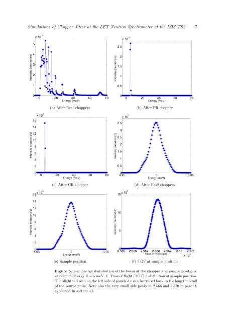
<strong>Simul<strong>at</strong>ions</strong> <strong>of</strong> <strong>Chopper</strong> <strong>Jitter</strong> <strong>at</strong> <strong>the</strong> <strong>LET</strong> <strong>Neutron</strong> <strong>Spectrometer</strong> <strong>at</strong> <strong>the</strong> ISIS TS2 6monitors interspersed <strong>at</strong> suitable loc<strong>at</strong>ions. Note th<strong>at</strong> <strong>the</strong> monitors used in <strong>the</strong> simul<strong>at</strong>ionsdoes not emul<strong>at</strong>e physical detectors, in as much as <strong>the</strong>y do not alter or absorb <strong>the</strong>detected neutron rays.The simul<strong>at</strong>ions used to gener<strong>at</strong>e <strong>the</strong> figures in this paper were typically run with 5∗10 8rays, which corresponds to approxim<strong>at</strong>ely 20 min. CPU-time on an ordinary dual-corelaptop.Fig. 5 shows <strong>the</strong> energy distribution <strong>of</strong> <strong>the</strong> beam <strong>at</strong> various positions in <strong>the</strong> instrument,with perfect beam choppers. Notice <strong>the</strong> multiple peaks after <strong>the</strong> first resolution choppers,reduced to <strong>the</strong> single 5 meV peak by <strong>the</strong> PR chopper, as would be expected in <strong>the</strong>physical instrument.To illustr<strong>at</strong>e <strong>the</strong> performance <strong>of</strong> <strong>the</strong> spectrometer, we have performed virtualexperiments using an incoherent elastic sc<strong>at</strong>terer[8]. Typical outcomes <strong>of</strong> <strong>the</strong>seexperiments are shown in fig. 6, while <strong>the</strong> deduced line width is shown in fig. 9.With highly imperfect beam choppers (large jitter), <strong>the</strong> detected energy distributioncan be seen to noticeably widen. This is illustr<strong>at</strong>ed in fig. 6, and clear effects are visiblefor jitter values <strong>of</strong> 10 µs. The line shape is almost perfectly Gaussian <strong>at</strong> zero jitter, <strong>the</strong>nbecomes increasingly Lorentzian with added jitter.As expected from <strong>the</strong> ToF equ<strong>at</strong>ion (2), <strong>the</strong> effect <strong>of</strong> <strong>the</strong> jitter depends significantlyon <strong>the</strong> speed <strong>of</strong> <strong>the</strong> choppers, as can be seen in fig. 7, where <strong>the</strong> intensity drops <strong>of</strong>f muchmore rapidly for increasing jitter, with <strong>the</strong> chopper set to <strong>the</strong> higher speed, as can beseen in fig. 7.Simple analytical calcul<strong>at</strong>ions <strong>of</strong> <strong>the</strong> time resolution <strong>at</strong> <strong>the</strong> detector positionsupports <strong>the</strong> simul<strong>at</strong>ed resolution increase with jitter, shown in figs. 6 and 9. Weuse <strong>the</strong> ToF equ<strong>at</strong>ion to calcul<strong>at</strong>e <strong>the</strong> allowed arrival times <strong>of</strong> neutrons <strong>at</strong> <strong>the</strong> detector,for different values <strong>of</strong> jitter.4.1. Side peaks in simul<strong>at</strong>ionsWhen building non-standard components, care and <strong>at</strong>tention is needed to avoidsimul<strong>at</strong>ion artefacts. As <strong>the</strong> chopper slits <strong>of</strong> <strong>the</strong> Res2 double choppers in <strong>the</strong> simul<strong>at</strong>ionsare triangular, and <strong>the</strong> guide openings <strong>of</strong> <strong>the</strong> double funnel system are rectangular, tryingto fit <strong>the</strong>m onto <strong>the</strong> rectangular guide opening <strong>of</strong> <strong>the</strong> double funnel system, resulted in<strong>the</strong> side peaks shown in <strong>the</strong> (x,t) diagram in fig. 8. Wh<strong>at</strong> happens is th<strong>at</strong> a short timebefore and after <strong>the</strong> double chopper turns to <strong>the</strong> open alignment, small slices <strong>of</strong> <strong>the</strong>10 mm wide guide openings are not covered by <strong>the</strong> absorbing section between <strong>the</strong> dualchopper slits (see fig. 2), which is 11 mm <strong>at</strong> its widest.In <strong>the</strong> actual instrument, <strong>the</strong> chopper slits have been shaped so as to avoid this effect.See fig. 3
<strong>Simul<strong>at</strong>ions</strong> <strong>of</strong> <strong>Chopper</strong> <strong>Jitter</strong> <strong>at</strong> <strong>the</strong> <strong>LET</strong> <strong>Neutron</strong> <strong>Spectrometer</strong> <strong>at</strong> <strong>the</strong> ISIS TS2 7(a) After Res1 choppers(b) After PR chopper(c) After CR chopper(d) After Res2 choppers(e) Sample position(f) TOF <strong>at</strong> sample positionFigure 5. a-e: Energy distribution <strong>of</strong> <strong>the</strong> beam <strong>at</strong> <strong>the</strong> chopper and sample positions,<strong>at</strong> nominal energy E = 5 meV. f: Time <strong>of</strong> flight (TOF) distribution <strong>at</strong> sample position.The slight tail seen on <strong>the</strong> left side <strong>of</strong> panels d,e can be traced back to <strong>the</strong> long time-tail<strong>of</strong> <strong>the</strong> source pulse. Note also <strong>the</strong> very small side peaks <strong>at</strong> 2.566 and 2.570 in panel f,explained in section 4.1