Push Button R55F Series Fiber-Optic Color Mark Sensors - Multiprox
Push Button R55F Series Fiber-Optic Color Mark Sensors - Multiprox
Push Button R55F Series Fiber-Optic Color Mark Sensors - Multiprox

You also want an ePaper? Increase the reach of your titles
YUMPU automatically turns print PDFs into web optimized ePapers that Google loves.
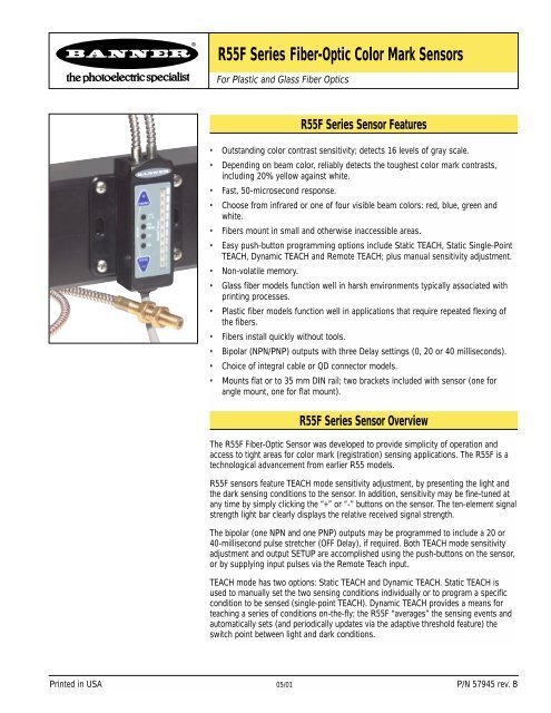
<strong>R55F</strong> <strong>Series</strong> <strong>Fiber</strong>-<strong>Optic</strong> <strong>Color</strong> <strong>Mark</strong> <strong>Sensors</strong>For Plastic and Glass <strong>Fiber</strong> <strong>Optic</strong>s<strong>R55F</strong> <strong>Series</strong> Sensor Features• Outstanding color contrast sensitivity; detects 16 levels of gray scale.• Depending on beam color, reliably detects the toughest color mark contrasts,including 20% yellow against white.• Fast, 50-microsecond response.• Choose from infrared or one of four visible beam colors: red, blue, green andwhite.• <strong>Fiber</strong>s mount in small and otherwise inaccessible areas.• Easy push-button programming options include Static TEACH, Static Single-PointTEACH, Dynamic TEACH and Remote TEACH; plus manual sensitivity adjustment.• Non-volatile memory.• Glass fiber models function well in harsh environments typically associated withprinting processes.• Plastic fiber models function well in applications that require repeated flexing ofthe fibers.• <strong>Fiber</strong>s install quickly without tools.• Bipolar (NPN/PNP) outputs with three Delay settings (0, 20 or 40 milliseconds).• Choice of integral cable or QD connector models.• Mounts flat or to 35 mm DIN rail; two brackets included with sensor (one forangle mount, one for flat mount).<strong>R55F</strong> <strong>Series</strong> Sensor OverviewThe <strong>R55F</strong> <strong>Fiber</strong>-<strong>Optic</strong> Sensor was developed to provide simplicity of operation andaccess to tight areas for color mark (registration) sensing applications. The <strong>R55F</strong> is atechnological advancement from earlier R55 models.<strong>R55F</strong> sensors feature TEACH mode sensitivity adjustment, by presenting the light andthe dark sensing conditions to the sensor. In addition, sensitivity may be fine-tuned atany time by simply clicking the “+” or “-” buttons on the sensor. The ten-element signalstrength light bar clearly displays the relative received signal strength.The bipolar (one NPN and one PNP) outputs may be programmed to include a 20 or40-millisecond pulse stretcher (OFF Delay), if required. Both TEACH mode sensitivityadjustment and output SETUP are accomplished using the push-buttons on the sensor,or by supplying input pulses via the Remote Teach input.TEACH mode has two options: Static TEACH and Dynamic TEACH. Static TEACH isused to manually set the two sensing conditions individually or to program a specificcondition to be sensed (single-point TEACH). Dynamic TEACH provides a means forteaching a series of conditions on-the-fly; the <strong>R55F</strong> “averages” the sensing events andautomatically sets (and periodically updates via the adaptive threshold feature) theswitch point between light and dark conditions.Printed in USA 05/01 P/N 57945 rev. B
<strong>R55F</strong> <strong>Series</strong> <strong>Fiber</strong>-<strong>Optic</strong> <strong>Color</strong> <strong>Mark</strong> <strong>Sensors</strong>Advantages of glass fiber optics for color mark sensing:• Randomly mixed bifurcated fiber bundles produce the best optics for color mark sensing.• Bundle of small fibers may be shaped at sensing end tip to match the color mark shape.• Best chemical resistance.<strong>R55F</strong> <strong>Series</strong> Glass <strong>Fiber</strong>-<strong>Optic</strong> Sensor ModelsVisible Red, 650 nmVisible Green, 525 nmVisible Blue, 475 nmVisible White, 450-650 nmInfrared, 880 nmModelNumberMaximum Sensing DistanceFor black-to-white contrastCable*SupplyVoltageOutputTypeVisible Red, 650 nm<strong>R55F</strong>V 0.060" dia. Bundle: 28 mm (1.1")5-wire 2 m (6.5') cable<strong>R55F</strong>VQ0.125" dia. Bundle: 110 mm (4.3")5-pin Euro-style QDVisible Green, 525 nm<strong>R55F</strong>VG 0.060" dia. Bundle: 12 mm (0.5")5-wire 2 m (6.5') cable<strong>R55F</strong>VGQ0.125" dia. Bundle: 50 mm (2.0")5-pin Euro-style QDVisible Blue, 475 nm<strong>R55F</strong>VB 0.060" dia. Bundle: 12 mm (0.5")<strong>R55F</strong>VBQ0.125" dia. Bundle: 50 mm (2.0")5-wire 2 m (6.5') cable5-pin Euro-style QD10 to 30V dcBipolarNPN/PNPVisible White, 450 - 650 nm<strong>R55F</strong>VW 0.060" dia. Bundle: 12 mm (0.5")5-wire 2 m (6.5') cable<strong>R55F</strong>VWQ0.125" dia. Bundle: 50 mm (2.0")5-pin Euro-style QDInfrared, 880 nm<strong>R55F</strong> 0.060" dia. Bundle: 40 mm (1.6")5-wire 2 m (6.5') cable<strong>R55F</strong>Q0.125" dia. Bundle: 140 mm (5.5")5-pin Euro-style QDAdvantages of plastic fiber optics for color mark sensing:• Plastic fibers may be repeatedly flexed.• Low cost.• Most models may be cut to fit in the field.<strong>R55F</strong> <strong>Series</strong> Plastic <strong>Fiber</strong>-<strong>Optic</strong> Sensor ModelsVisible Red, 650 nmVisible Green, 525 nmVisible Blue, 475 nmVisible White, 450-650 nmModelNumberMaximum Sensing DistanceFor black-to-white contrastCable*SupplyVoltageOutputTypeVisible Red, 650 nm<strong>R55F</strong>P<strong>R55F</strong>PQ0.040" dia. <strong>Fiber</strong>s: 60 mm (2.4")5-wire 2 m (6.5') cable5-pin Euro-style QDVisible Green, 525 nm<strong>R55F</strong>PG<strong>R55F</strong>PGQVisible Blue, 475 nm0.040" dia. <strong>Fiber</strong>s: 28 mm (1.1")5-wire 2 m (6.5') cable5-pin Euro-style QD10 to 30V dcBipolarNPN/PNP<strong>R55F</strong>PB<strong>R55F</strong>PBQ0.040" dia. <strong>Fiber</strong>s: 28 mm (1.1")5-wire 2 m (6.5') cable5-pin Euro-style QDVisible White, 450 - 650 nm<strong>R55F</strong>PW<strong>R55F</strong>PWQ0.040" dia. <strong>Fiber</strong>s: 28 mm (1.1")5-wire 2 m (6.5') cable5-pin Euro-style QD* 9m (30') cables are available by adding suffix “W/30” to the model number of any cabled sensor (e.g., <strong>R55F</strong>V W/30). A model with a QDconnector requires a mating cable (see page 11).page 2Banner Engineering Corp. • Minneapolis, U.S.A.www.bannerengineering.com • Tel: 763.544.3164
<strong>R55F</strong> <strong>Series</strong> <strong>Fiber</strong>-<strong>Optic</strong> <strong>Color</strong> <strong>Mark</strong> <strong>Sensors</strong>BPlastic fibersshown; procedureis identical forglass fibers<strong>Fiber</strong>ClipCAGlass <strong>Fiber</strong> Installation Procedure:1) Check to see that a rubber o-ring is pre-installed on each fiber control end.2) Slide the fiber clip to the open position (A).3) Insert one fiber end into each port (B). <strong>Push</strong> firmly on the fiber ends to compressthe o-rings and align the grooves in the fiber ends with the slot in the fiber clip.4) Slide the fiber clip back into place, locking the fibers into position (C).Plastic <strong>Fiber</strong> Installation Procedure:NOTE: <strong>R55F</strong> sensors accept 0.75, 1.0, and 1.5 mm (0.03", 0.04", and 0.06") corediameter plastic fibers.1) Cut the “control ends” (sensor ends) of the plastic fiber(s) to the desired lengthper the procedure which accompanies the fiber assembly.Figure 1. Installing fibers into the <strong>R55F</strong><strong>Series</strong> sensor2) If not already done, separate bifurcated fibers by approximately 2" from the controlends.3) Slide the fiber clip to the open position (A).4) Insert the fiber ends into each port and push them in as far as they will go (B).5) Slide the fiber clip back into place, locking the fibers into position (C).<strong>Fiber</strong> <strong>Optic</strong> Mounting ConsiderationsMount the sensing end of the fiber optic assembly so that the light image is totallycontained within the boundaries of the color mark to be sensed. The light image ismade smaller by moving the sensing tip closer to the surface of the material to besensed.When sensing marks on shiny (specular) materials, such as metal, plastic or glossypaper, mount the sensing tip of the fiber at approximately 15° from perpendicular tothe material surface to minimize strong direct reflections.Isolate the fiber mounting from vibration. Also, maintain mechanical stability of thesurface to be sensed (e.g., stabilize web flutter at the sensing point).Banner Engineering Corp. • Minneapolis, U.S.A.www.bannerengineering.com • Tel: 763.544.3164page 3
<strong>R55F</strong> <strong>Series</strong> <strong>Fiber</strong>-<strong>Optic</strong> <strong>Color</strong> <strong>Mark</strong> <strong>Sensors</strong>RUN ModeUsing the <strong>R55F</strong> <strong>Series</strong> SensorNormal operation of the <strong>R55F</strong> is called RUN mode. The LED indicators (seeFigure 2) operate as follows in RUN mode:Output Conducting LED: ON when outputs are activeDelay Configuration Indicator LED: OFF No OFF Delay is programmedON 20 or 40-ms OFF Delay is programmedLight Operate LED: ON to indicate Light Operate configurationOutputConductingLEDDelayConfigurationIndicator LEDLO(Light Operate)LED*DO(Dark Operate)LED*DynamicTEACH (+)<strong>Push</strong> <strong>Button</strong>10-SegmentLight BarSwitchPointStaticTEACH (-)<strong>Push</strong> <strong>Button</strong>Dark Operate LED: ON to indicate Dark Operate configuration(NOTE: Since either one of these is always ON when the sensor is operating, thecombined Light/Dark Operate LEDs also provide a functional Power-ON indication.)10-Segment Light Bar: indicates signal strength, with respect to the sensingthreshold (“Switch Point”).* Either LO or DO LED is ONwhenever sensor has powerand is in RUN modeFigure 2. <strong>R55F</strong> <strong>Series</strong> sensor featuresTEACH ModesThe sensitivity of the <strong>R55F</strong> may be quickly optimized by using one of two available TEACH modes: Static TEACH or DynamicTEACH. Either may be performed using the push buttons on the sensor, or remotely, using a remote switch or process controllerconnected to the sensor’s gray wire (see page 8). Either a sensing window or a specific point may be taught.Static TEACHIn Static TEACH mode, the sensor learns the light condition and the dark condition, each one time. Sensitivity is automatically setto place the switch point midway between the two conditions. In addition, the condition taught first becomes the output ONcondition.Sensitivity may be adjusted at any time when the sensor is in RUN mode by clicking the “+” and “-” buttons. Each click translatesto 1/2 segment on the signal strength light bar. For best sensing reliability, the light and dark conditions should register equallydistant from the switch point on the signal strength light bar.Single-Point TEACHThe <strong>R55F</strong> sensor also may be taught a single specific target, using an alternate Static TEACH procedure. The sensor will senseonly the mark taught and will ignore signals both stronger and weaker. The sensitivity to the taught mark then may be adjusted upor down.To perform single-point TEACH, place the target in front of the sensor. Press and hold the “Static” button until the LO and DOLEDs begin to flash, then double-click the Static button. If the single point was successfully taught, the two center sections of thebar graph will flash.Manually adjust the sensitivity by clicking either the “+” or “-” button; the bar graph will flash two segments centered about thesensing point. If the sensitivity is increased (-), the two lighted segments will become closer together, and farther apart if thesensitivity is decreased (+). If the segments do not flash while the sensitivity is being adjusted, the setting has reached itsmaximum and cannot be adjusted further.page 4Banner Engineering Corp. • Minneapolis, U.S.A.www.bannerengineering.com • Tel: 763.544.3164
LOLOLOLOLO<strong>R55F</strong> <strong>Series</strong> <strong>Fiber</strong>-<strong>Optic</strong> <strong>Color</strong> <strong>Mark</strong> <strong>Sensors</strong>See page 8 for RemoteTEACH proceduresStatic TEACH Procedure - <strong>Push</strong> <strong>Button</strong><strong>Push</strong> <strong>Button</strong>Resulting Indicator StatusPress and hold STATIC buttonuntil LO and DO indicatorsalternately flash, then releasebutton.Press and Hold ≥ 2 secondsSTATIC–DOSETUPOFFDelaySwitch Point+DYNAMICLO and DO: Alternately flash green: ON amber (indicating ready toteach output ON condition)Light Bar: Goes OFFTEACH Condition #1(Output ON state)Present the output ON sensingcondition and single-clickSTATIC button.Single-clickSTATIC–DOSETUPOFFDelaySwitch Point+DYNAMICLO and DO: Alternately flash Green: OFF (indicating ready to teachoutput OFF condition)Light Bar: Remains OFFTEACH Condition #2(Output OFF state)Present the output OFFsensing condition and singleclickSTATIC button.Single-clickSTATIC–DOSETUPOFFDelaySwitch Point+DYNAMICSignal StrengthLight BarContrast accepted: one of the tensegments flashes for three seconds toindicate relative contrast, and then thesensor enters RUN mode.Contrast too low: every other segmentflashes for three seconds to indicate lowcontrast, and the sensor returns to TEACHCondition #1.NOTES:1) The sensor will return to RUN mode if either TEACH condition is not registered within 90 seconds. Also,TEACH mode may be cancelled by pressing and holding the push button for ≥ 2 seconds. In either case, thesensor will revert to the previous conditions taught (i.e., exit without save).2) If the sensing conditions are accepted at the end of TEACH Condition #2, the signal strength light bar flashesone of its ten segments for three seconds to indicate relative sensing contrast. The higher the flashingsegment, the higher the measured sensing contrast. High contrast relates directly to sensing reliability. Highcontrastsensing applications are most tolerant of sensing variables, such as web flutter or variations in colormark color or print density.Static Single-Point TEACH Procedure - <strong>Push</strong> <strong>Button</strong><strong>Push</strong> <strong>Button</strong>Resulting Indicator StatusPress and hold STATIC buttonuntil LO and DO indicatorsalternately flash, then releasebutton.Press and Hold ≥ 2 secondsSTATIC–DOSETUPOFFDelaySwitch Point+DYNAMICLO and DO: Alternately flash green: ON amber (indicating ready toteach output ON condition)Light Bar: Goes OFFTEACH Condition to beSensed (Output ON state)Present the output ON sensingcondition and double-clickSTATIC button.Double-clickSTATIC–DOSETUPOFFDelaySwitch Point+DYNAMICLO or DO: depending on condition oftaught: OFFLight Bar: Two center segments are litif TEACH was successful.Banner Engineering Corp. • Minneapolis, U.S.A.www.bannerengineering.com • Tel: 763.544.3164page 5
LOLOLO<strong>R55F</strong> <strong>Series</strong> <strong>Fiber</strong>-<strong>Optic</strong> <strong>Color</strong> <strong>Mark</strong> <strong>Sensors</strong>Dynamic TEACHDynamic TEACH is used to program sensitivity during actual machine run conditions. DuringDynamic TEACH, the <strong>R55F</strong> samples many color marks against their background material andautomatically sets the sensitivity at the optimum level. Dynamic TEACH activates the sensor’sadaptive threshold system, which continuously tracks minimum and maximum signal levels, andautomatically maintains centering of the switch point between the light and dark conditions. Theadaptive threshold system remains in effect during RUN mode to automatically adjust for changesin the light or the dark conditions.When Dynamic TEACH mode is used to program sensitivity, the output ON state must be assignedto either the light or dark condition using the SETUP mode (see page 7).Sensitivity may be adjusted at any time when the sensor is in RUN mode by clicking the “+” and “-”buttons. However, when a manual adjustment is made, the adaptive threshold system is disabled(cancelled).Dynamic TEACH Procedure - <strong>Push</strong> button<strong>Push</strong> <strong>Button</strong>Resulting Indicator StatusSee page 8 for RemoteTEACH proceduresPress and hold DYNAMICbutton until LO and DOindicators alternately flash.Press and Hold ≥ 2 secondsSTATIC–DOSETUPOFFDelaySwitch Point+DYNAMICLO and DO: Alternately flash green: OFFLight Bar: Goes OFFContinue depressing theDYNAMIC button whilesampling light and darksensing conditions.Continue to DepressWhile Sensor SamplesLight and Dark ConditionsSTATIC–DOSETUPOFFDelaySwitch Point+DYNAMICLO and DO: Alternately flash green: OFFLight Bar: Remains OFFRelease the DYNAMIC buttonwhen finished sampling lightand dark sensing conditions.STATIC–DOSETUPOFFDelaySwitch PointRelease+DYNAMICContrast accepted: one of the tensegments flashes for three seconds toindicate relative contrast, and the sensorenters RUN mode.Contrast too low: five light bar segmentsflash for three seconds to indicate lowcontrast, and sensor reverts to thepreviously taught conditions.NOTES:1) If the sensing conditions are accepted at the end of Dynamic TEACH, the signal strength light bar flashes oneof its ten segments for three seconds to indicate relative sensing contrast. The higher the flashing segment,the higher the measured sensing contrast. High contrast relates directly to sensing reliability. High contrastsensing applications are most tolerant of sensing variables, such as web flutter or variations in color markcolor or print density.2) If the sensor does not measure enough contrast at the end of Dynamic TEACH, every other segment of thesignal strength light bar flashes in unison for three seconds to warn of unacceptably low contrast, and thesensor returns to RUN mode with its previously taught conditions.page 6Banner Engineering Corp. • Minneapolis, U.S.A.www.bannerengineering.com • Tel: 763.544.3164
<strong>R55F</strong> <strong>Series</strong> <strong>Fiber</strong>-<strong>Optic</strong> <strong>Color</strong> <strong>Mark</strong> <strong>Sensors</strong>Press and HoldBoth <strong>Push</strong> <strong>Button</strong>sFigure 3. SETUP modeSETUP+DYNAMICSTATIC–OFFDelayLODOSwitch PointSETUP ModeSETUP mode is used to configure sensor output response for:- Light or Dark operate- 20- or 40-millisecond pulse stretcher (OFF delay), if required.It will be necessary to access SETUP mode only if the settings which result fromTEACH mode programming are not the settings required for the application. Thestatus LEDs indicate the output response configuration when the sensor is in RUNmode, as follows:- LO indicator ON = output is light operate- DO indicator ON = output is dark operate- OFF Delay indicator ON = either 20- or 40-millisecond delay is programmed- OFF Delay indicator OFF = no output delay is programmedTo change the output response settings;1) Press and hold BOTH push buttons until the signal strength light bar turns OFF.2) Click EITHER push button to toggle through the six possible settingsindicated as follows:Output ConfigurationDelayIndicatorLOIndicatorDOIndicatorLight operate with no delay OFF ON OFFLight operate with 20 ms delay Flashing ON OFFLight operate with 40 ms delay ON ON OFFDark operate with no delay OFF OFF ONDark operate with 20 ms delay Flashing OFF ONDark operate with 40 ms delay ON OFF ON3) Press and hold both push buttons until the signal strength light bar turns ON,indicating return to RUN mode.NOTE: If SETUP mode programming is interrupted and remains inactive for 30seconds, the sensor returns to RUN mode with the most recent settings(i.e., exit and save current selection).Banner Engineering Corp. • Minneapolis, U.S.A.www.bannerengineering.com • Tel: 763.544.3164page 7
<strong>R55F</strong> <strong>Series</strong> <strong>Fiber</strong>-<strong>Optic</strong> <strong>Color</strong> <strong>Mark</strong> <strong>Sensors</strong>Remote ProgrammingThe gray wire of the <strong>R55F</strong> may be connected to a remote switch or to a processcontroller to:- Set sensitivity via either Static or Dynamic TEACH mode- Set output response via SETUP mode- Disable the push button functionsSwitch OpenSwitch Closedto dc common0.04 < T < 0.8 secA remote programming switch is connected between the gray wire and dc common (seeHookup diagrams on page 11). The switch may be either a normally-open contact, or anopen-collector NPN transistor with its emitter connected to dc common.Figure 4. Input pulse timingRemote programming is accomplished using a specified sequence of input pulses.The duration of each pulse is defined as:0.04 seconds < T < 0.8 seconds (40 ms < T< 800 ms)Remote Static TEACH Mode1) Present the Output ON condition to the fiber sensing end and pulse the RemoteTEACH input once.2) Wait at least 0.8 seconds, present the Output OFF condition, and pulse the RemoteTEACH input once.If sensing contrast is adequate, the sensor flashes one segment of the signal strengthlight bar for 3 seconds to indicate relative contrast, and then enters RUN mode.If contrast is too low, the sensor flashes five segments of the signal strength light barin unison to warn of unacceptably low contrast, and returns to re-teach the Output ONcondition (Step 1).Remote Static Single-Point TEACHThe single-point TEACH may also be performed using the remote wire. Present thetarget and single-click the remote wire. Wait for at least 0.8 second, then double-clickthe remote wire. If the TEACH is successful, the sensor will flash the middle two LEDsof the bar graph, and return to RUN mode.PresentOutput ONConditionT> 0.8 secPresentOutput OFFConditionFigure 5. Static TEACH modePresentOutput ONConditionTDouble-ClickT T T> 0.8 secTFigure 6. Static Single-Point TEACH modeRemote Dynamic TEACH Mode1) Hold the TEACH input low for > 2 seconds2) Continue holding the TEACH input low while presenting light and dark sensingconditions. Open switch when finished teaching.If sensing contrast is adequate, the sensor flashes one segment of the signal strengthlight bar for 3 seconds to indicate relative contrast, and then enters RUN mode.If contrast is too low, the sensor flashes five segments of the signal strength light barin unison to warn of unacceptably low contrast, and returns to RUN mode with itspreviously taught conditions.> 2 secTEACH Lightand DarkConditionsFigure 7. Dynamic TEACH modepage 8Banner Engineering Corp. • Minneapolis, U.S.A.www.bannerengineering.com • Tel: 763.544.3164
<strong>R55F</strong> <strong>Series</strong> <strong>Fiber</strong>-<strong>Optic</strong> <strong>Color</strong> <strong>Mark</strong> <strong>Sensors</strong>Tetc.Remote SETUP ModeTTwo pulsesto EnterSETUPT> 0.8 secFigure 8. SETUP modeT> 0.8 secSequentialpulses to togglebetween configuration choicesT T T TPulse four times to enableor disable push buttonFigure 9. <strong>Push</strong> button lockoutTTTT> 0.8 secT1) To enter SETUP mode, pulse once, wait 0.04 to 0.8 seconds, then pulse again.2) Wait > 0.8 seconds, then enter sequential pulses to toggle between the sixoutput configuration choices (see page 7). Spacing between sequential pulsesmust be > 0.8 seconds.3) To exit SETUP mode, hold the TEACH input low for > 2 seconds.Locking Out (Disabling) the <strong>Push</strong> <strong>Button</strong>sPulse four times to disable (or to re-enable) the push buttons.<strong>R55F</strong> <strong>Series</strong> Sensor DimensionsPlastic <strong>Fiber</strong>10.0 mm(0.39")30.0 mm(1.18")Glass <strong>Fiber</strong>12.9 mm(0.51")10.0 mm(0.39")25.0 mm(0.99")12.9 mm(0.51")Quick-DisconnectModelsCabledModels24.5 mm(0.97")+DYNAMIC+DYNAMIC35.0 mm(1.40")85.4 mm(3.36")SETUPOFFDelayLOSwitch PointSETUPOFFDelayLOSwitch PointDODOSTATIC–4.5 mm(0.18")STATIC–11.6 mm(0.46")Banner Engineering Corp. • Minneapolis, U.S.A.www.bannerengineering.com • Tel: 763.544.3164page 9
<strong>R55F</strong> <strong>Series</strong> <strong>Fiber</strong>-<strong>Optic</strong> <strong>Color</strong> <strong>Mark</strong> <strong>Sensors</strong><strong>R55F</strong> <strong>Series</strong> Sensor SpecificationsSupply InputSupply Protection CircuitryOutput ConfigurationOutput RatingOutput ProtectionOutput ResponseAdjustments(see pages 4 - 9)Indicator LEDsConstruction10 to 30V dc (10% maximum ripple) at less than 70 mA, exclusive of loadProtected against reverse polarity and transient voltagesBipolar (NPN and PNP)150 mA max each output @ 25°C (derate ≈ 1 mA per °C increase)OFF-state leakage current: < 5 µA @ 30V dcON-state saturation voltage: PNP Output < 1V @ 10 mA and 1.5V @ 150 mANPN Output < 200 mV @ 10 mA and 1V @ 150 mAProtected against false pulse on power-up and continuous overload or short-circuit of outputs.50 microsecondsNOTE: 100 millisecond delay on power-up; outputs do not conduct during this time.Using push buttons (“+” Dynamic and “-” Static):Manually adjust Switch Point using “+” or “-” buttonsDynamic TEACH (teach on-the-fly) sensitivity adjustmentStatic TEACH sensitivity adjustmentLight operate/Dark operateOFF Delay select: 0 milliseconds, 20 milliseconds or 40 millisecondsUsing Remote TEACH input (gray wire):Dynamic TEACH (teach on-the-fly) sensitivity adjustmentStatic TEACH sensitivity adjustmentLight operate/Dark operateOFF Delay select: 0 milliseconds, 20 milliseconds or 40 milliseconds<strong>Push</strong> button lockout for security10-segment (green) light bar indicates signal strengthLight Operate (green)Dark Operate (green)Outputs Conducting (yellow)OFF Delay (green): SETUP Mode: OFF — no delay RUN Mode: OFF — no delayFlashing — 20 ms delayON — 20 or 40 ms DelayON — 40 ms delayHousing: Black ABS/polycarbonate blend; nylon fiber clipmounts to standard 35 mm DIN rail1 stainless steel right angle bracket and 1 PBT polyester bracket for mounting to flat surfaces also includedwith sensorEnvironmental Rating IEC IP67; NEMA 6ConnectionsOperating ConditionsApplication NotesPower: 2 m or 9 m PVC-jacketed 5-conductor cable or 5-pin Euro-style quick-disconnect (QD) connector<strong>Fiber</strong>s: <strong>Fiber</strong> clip (no tool required)Temperature: -10° to +55° C (+14° to 131° F)Maximum Relative Humidity: 90% at 50° C (non-condensing)• Do not mount the fiber tip directly perpendicular to shiny surfaces; position it at approximately a 15° anglein relation to the sensing target• Minimize web or product “flutter” whenever possible to maximize sensing reliabilitypage 10Banner Engineering Corp. • Minneapolis, U.S.A.www.bannerengineering.com • Tel: 763.544.3164
<strong>R55F</strong> <strong>Series</strong> <strong>Fiber</strong>-<strong>Optic</strong> <strong>Color</strong> <strong>Mark</strong> <strong>Sensors</strong>Cabled Models<strong>R55F</strong> <strong>Series</strong> Sensor HookupsQuick-Disconnect ModelsbnbuwhbkgyLoadLoad+10-30V dc–bnbuwhbkgyLoadLoad+10-30V dc–Remote TeachRemote TeachBoth brackets are included with sensor.Mounting BracketsSMB<strong>R55F</strong>RA• Side-mounting bracket• 19 ga stainless steelSMB<strong>R55F</strong>01• Flat-mounting bracket• Molded PBT polyester3.5 mm(0.14")7.2 mm(0.28")4x 5.0 mm(0.20")40.0 mm(1.58")4.5 mm(0.18")2x ø5.4 mm(0.21")65.0 mm(2.56")15.0 mm(0.59")29.5 mm(1.16")6.0 mm(0.24")35.0 mm(1.40") 50.8 mm(2.00")35.0 mm(1.38")20.0 mm(0.79")4x R2.5(0.10")2.5 mm(0.10")4.5 mm(0.18")10.0 mm(0.40")7.5 mm(0.30")30.4 mm(1.20")50.8 mm(2.00")64.0 mm(2.52")Quick-Disconnect (QD) CablesStyle Model Length Connector5-Pin EuroMQDC1-506MQDC1-515MQDC1-530MQDC1-506RAMQDC1-515RAMQDC1-530RA2 m (6.5')5 m (15')9 m (30')2 m (6.5')5 m (15')9 m (30')StraightStraightStraightRight-angleRight-angleRight-angleBrown WireBlack WireWhite WireBlue WireGray WireBanner Engineering Corp. • Minneapolis, U.S.A.www.bannerengineering.com • Tel: 763.544.3164page 11
<strong>R55F</strong> <strong>Series</strong> Glass and Plastic <strong>Fiber</strong>-<strong>Optic</strong> <strong>Color</strong> <strong>Mark</strong> <strong>Sensors</strong>Euro-Style Field-Wireable ConnectorsContacts: Gold-plated; 4-pin models rated 250V ac/dc max., 4 A max.; 5-pin models rated 50V ac/dc max., 4A max.Cable Diameter: 4.0 to 5.0 mm (0.16 to 0.20")Temperature: -25° to +90°C (-13° to +194°F)Environmental Rating: NEMA 6P, IP 67StyleModelGenderDimensionsPin-outFIC-M12M5Male15.0 mm(0.59")60 mm(2.4")10 mm(0.4")M12 x 120 mm(0.8")5-PinStraightFIC-M12F5Female15.0 mm(0.59")60 mm(2.4")10 mm(0.4")M12 x 120 mm(0.8")FIC-M12M5AMale41 mm(1.6")20 mm(0.8")5-PinRight-angle30.5 mm(1.20")M12 x 120 mm(0.8")FIC-M12F5AFemale15.0 mm(0.59")!WARNING . . . Not To Be Used for Personnel ProtectionNever use these products as sensing devices for personnel protection. Doing so could lead to serious injury or death.These sensors do NOT include the self-checking redundant circuitry necessary to allow their use in personnel safetyapplications. A sensor failure or malfunction can cause either an energized or de-energized sensor output condition. Consult your currentBanner Safety Products catalog for safety products which meet OSHA, ANSI and IEC standards for personnel protection.WARRANTY: Banner Engineering Corp. warrants its products to be free from defects for one year. Banner Engineering Corp. will repair orreplace, free of charge, any product of its manufacture found to be defective at the time it is returned to the factory during the warrantyperiod. This warranty does not cover damage or liability for the improper application of Banner products. This warranty is in lieu of anyother warranty either expressed or implied.Banner Engineering Corp., 9714 Tenth Ave. No., Minneapolis, MN 55441 • Phone: 763.544.3164 • www.bannerengineering.com • Email: sensors@bannerengineering.com