Thermal treatment method for tuning the lasing wavelength of a DFB ...
Thermal treatment method for tuning the lasing wavelength of a DFB ...
Thermal treatment method for tuning the lasing wavelength of a DFB ...

Create successful ePaper yourself
Turn your PDF publications into a flip-book with our unique Google optimized e-Paper software.
International Workshop on Photonics and Applications. Hanoi, Vietnam. April 5-8, 2004<strong>Thermal</strong> <strong>treatment</strong> <strong>method</strong> <strong>for</strong> <strong>tuning</strong> <strong>the</strong> <strong>lasing</strong> <strong>wavelength</strong><strong>of</strong> a <strong>DFB</strong> fiber laser using coil heatersHa Huy Thanh and Bui Trung DzungNational Center <strong>for</strong> Technology Progress (NACENTECH)C6-Thanh Xuan Bac-Hanoi-VietnamAbstract: The popular <strong>method</strong> <strong>for</strong> <strong>tuning</strong> <strong>the</strong> <strong>lasing</strong> <strong>wavelength</strong> <strong>of</strong> a <strong>DFB</strong> fiberlaser is to apply strains along <strong>the</strong> fiber grating using a Piezoelectric Transducer(PZT) [1]. Although <strong>the</strong> <strong>tuning</strong> range <strong>of</strong> 3nm can be obtained by this way, <strong>the</strong>spliced connections between <strong>the</strong> grating and <strong>the</strong> conventional single-mode fibersare <strong>of</strong>ten broken down, especially when over stretched. To avoid this risk, in thispaper, we propose a safer compact <strong>tuning</strong> <strong>method</strong>. By controlling <strong>the</strong> DC current in<strong>the</strong> coil heaters around <strong>the</strong> <strong>DFB</strong> grating, we obtained a <strong>tuning</strong> range up to 2.3nmwithout any mode hoping.Keywords: <strong>DFB</strong> fiber laser, optical communications, tunable fiber laser.IntroductionThe development <strong>of</strong> high bit-rate, coherent optical communication systems usingWavelength Division Multiplexing (WDM) technique requires that <strong>the</strong> laser source have avery narrow linewidth, single frequency, stable polarization and tunable <strong>wavelength</strong>. TheDistributed Feedback (<strong>DFB</strong>) fiber laser has been emerging as a promising alternative to <strong>the</strong><strong>DFB</strong> semiconductor laser <strong>for</strong> use in CATV networks and high bit rate WDMcommunications. The advantages <strong>of</strong> <strong>the</strong> <strong>DFB</strong> fiber laser include fiber compatibility,compact size, and ultra-narrow linewidth [2].The tunable <strong>DFB</strong> fiber laser can be also obtained by applying strains along <strong>the</strong> <strong>DFB</strong>grating. H.Yoon et. al. proposed a <strong>method</strong> using a PZT stretcher to tune <strong>the</strong> <strong>lasing</strong><strong>wavelength</strong> <strong>of</strong> a <strong>DFB</strong> fiber laser [1]. The PZT stretcher creates a nearly uni<strong>for</strong>m straindistribution along <strong>the</strong> grating, which would make <strong>the</strong> shift <strong>of</strong> <strong>the</strong> <strong>lasing</strong> <strong>wavelength</strong>.Although, this <strong>method</strong> can provide a <strong>tuning</strong> range up to 3nm without any mode hoping, <strong>the</strong><strong>for</strong>ce-based <strong>method</strong>s generally show to be unsafe to <strong>the</strong> grating, especially when <strong>the</strong>grating is over-stretched. The structure <strong>of</strong> a <strong>DFB</strong> fiber laser includes a phase-shifted <strong>DFB</strong>grating whose two ends are spliced with two conventional single mode fibers. When weover-stretch <strong>the</strong> grating or stretch it several times, <strong>the</strong> two spliced connections are possiblydisconnected. Fur<strong>the</strong>rmore, <strong>the</strong> stretching and twisting are two main sources that cause <strong>the</strong>instability <strong>of</strong> <strong>the</strong> polarization mode <strong>of</strong> <strong>the</strong> laser.To avoid this risk, in this paper, we propose a new compact and safer <strong>the</strong>rmal<strong>treatment</strong> <strong>method</strong> that can provide <strong>the</strong> <strong>tuning</strong> range up to 2.3 nm and no mode hoping wasseen. The heated Ni-Cr coils were employed to create a nearly uni<strong>for</strong>m temperaturedistribution along <strong>the</strong> grating. We also tested <strong>the</strong> operational parameters <strong>of</strong> <strong>the</strong> laser across<strong>the</strong> <strong>tuning</strong> range.279
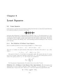
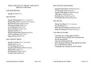
International Workshop on Photonics and Applications. Hanoi, Vietnam. April 5-8, 2004Theory BasisThe single frequency <strong>of</strong> a <strong>DFB</strong> laser is obtained by creating a phase-shift <strong>of</strong> π/2 in <strong>the</strong><strong>DFB</strong> structure. The single <strong>wavelength</strong> <strong>of</strong> <strong>the</strong> laser is equal to <strong>the</strong> Bragg <strong>wavelength</strong> <strong>of</strong> <strong>the</strong>structure [3].The Bragg <strong>wavelength</strong> <strong>of</strong> <strong>the</strong> grating depends on <strong>the</strong> effective index <strong>of</strong> refraction <strong>of</strong><strong>the</strong> core and <strong>the</strong> periodicity <strong>of</strong> <strong>the</strong> grating. The effective index <strong>of</strong> refraction, as well as <strong>the</strong>periodic spacing between <strong>the</strong> grating planes, will be affected by changes in temperature.Consequently, <strong>the</strong> shift ∆λ B in <strong>the</strong> Bragg center <strong>wavelength</strong> λ B is dependent on <strong>the</strong> changesin <strong>the</strong> temperature, which is given as:∆λ= λBα Λ+ αBo(Λ)FBGWhere ∆T FBG =(T H -T O ) is <strong>the</strong> heating temperature in degree oC, λ Bo is <strong>the</strong> Bragg<strong>wavelength</strong> at <strong>the</strong> reference temperature T O ,⎡ 1 ∂Λ ⎤αΛ = is <strong>the</strong> <strong>the</strong>rmal expansion coefficient⎢⎣Λ∂Τ ⎥⎦∆Tαn⎡ 1= ⎢⎢⎣neff∂Λ ⎤⎥ is <strong>the</strong>rmo-optic coefficient∂Τ ⎥⎦The rate <strong>of</strong> refractive index change is higher than <strong>the</strong> period changes, and which is <strong>the</strong>main contributor to <strong>the</strong> <strong>wavelength</strong> shift. The <strong>wavelength</strong> shows high sensitivity at highervalues <strong>of</strong> T H . Though, under 100 o C, <strong>the</strong> change is considered linear [4]. In addition, <strong>the</strong>fiber Bragg gratings show excellent temperature stability in <strong>the</strong> temperature under 300 o C[5]. It is, <strong>the</strong>re<strong>for</strong>e, permissible to think <strong>of</strong> a <strong>the</strong>rmal <strong>method</strong> <strong>for</strong> <strong>tuning</strong> <strong>the</strong> <strong>lasing</strong><strong>wavelength</strong> <strong>of</strong> a <strong>DFB</strong> fiber laser.ExperimentThe <strong>DFB</strong> fiber laser used in <strong>the</strong> experiment has <strong>the</strong> following specifications: gratinglength: 5cm, single <strong>wavelength</strong>: 1551nm, single polarization mode, linewidth: 30KHz,pumping power 9mW, maximum power peak: 40mW, SNR >50dB, SMSR > 40dB [6].The Figure 1 shows <strong>the</strong> optical spectrum <strong>of</strong> <strong>the</strong> laser.0Output Power dBm-20-40-60-801550.0 1550.5 1551.0 1551.5 1552.0WavelengthFigure 1: Optical spectrum <strong>of</strong> <strong>the</strong> laser280
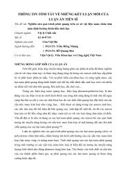
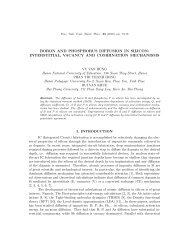
International Workshop on Photonics and Applications. Hanoi, Vietnam. April 5-8, 2004The basic idea is to create a controllable uni<strong>for</strong>m <strong>the</strong>rmal distribution along <strong>the</strong>grating. We rolled <strong>the</strong> Ni-Cr wire to <strong>for</strong>m <strong>the</strong> coils with <strong>the</strong> internal diameter <strong>of</strong> 300µmand external diameter <strong>of</strong> 550µm around <strong>the</strong> <strong>DFB</strong> structure. The Ni-Cr coils were placed ona high temperature resistance Silicon substrate. By controlling <strong>the</strong> DC current intensityinside <strong>the</strong> coils, we created a nearly uni<strong>for</strong>m temperature distribution along <strong>the</strong> grating.<strong>DFB</strong> fiber gratingNi-Cr wireφ=550µmFigure 2: The Ni-Cr coil <strong>for</strong> heating <strong>the</strong> <strong>DFB</strong> fiber gratingWe put <strong>the</strong> <strong>DFB</strong> fiber grating inside <strong>the</strong> Ni-Cr coil heaters, pumped <strong>the</strong> grating byGaAlAsP diode laser 980nm, which was controlled by a Laser Diode Driver Model 525.Changing <strong>the</strong> DC current inside <strong>the</strong> Ni-Cr wire, we controlled <strong>the</strong> temperature range from22 o C to 135 o C. Increasing <strong>the</strong> temperature by controlling <strong>the</strong> DC current intensity, andobserving <strong>the</strong> laser spectrum on <strong>the</strong> Optic Spectrum Analyzer (OSA) AQ 6317B, werealized <strong>the</strong> linear shifting <strong>of</strong> <strong>the</strong> <strong>lasing</strong> <strong>wavelength</strong>. The <strong>tuning</strong> range was 2.3nm and nomode hoping was seen throughout <strong>the</strong> <strong>tuning</strong> range (Fig. 3).1553.51553.0Lasing Wavelength1552.51552.01551.51551.020 40 60 80 100 120 140TemperatureFigure 3: The shift <strong>of</strong> <strong>the</strong> <strong>lasing</strong> <strong>wavelength</strong> vs. <strong>the</strong> changes <strong>of</strong> <strong>the</strong> temperatureUsing Delayed Self-Heterodyne technique (Fig. 4) [7], we tested <strong>the</strong> stability <strong>of</strong> <strong>the</strong>linewidth across <strong>the</strong> <strong>tuning</strong> range. At <strong>wavelength</strong> <strong>of</strong> 1551nm, <strong>the</strong> output power is 3dBmand <strong>the</strong> linewidth is 30KHz. At <strong>the</strong> <strong>wavelength</strong> <strong>of</strong> 1553.3nm, <strong>the</strong> output power <strong>of</strong> 3.2dBm,<strong>the</strong> linewidth is 30.4KHz.281
International Workshop on Photonics and Applications. Hanoi, Vietnam. April 5-8, 2004980nmWDM 980/1550<strong>DFB</strong> inside <strong>the</strong> coil heatersIsolator12 km delay fiberDetector+RFSpectrumAnalyzerAOMAttenuatorFigure 4: The Delayed Self-Heterodyne technique <strong>for</strong> measuring <strong>the</strong>linewidth <strong>of</strong> <strong>the</strong> laserUsing <strong>the</strong> setup shown in <strong>the</strong> figure 5, we tested <strong>the</strong> single polarization mode stability<strong>of</strong> <strong>the</strong> laser throughout <strong>the</strong> <strong>tuning</strong> range. At 1551nm, <strong>the</strong> laser operated in <strong>the</strong> singlepolarization mode. The polarization extinction ratio was better than 20dB. At 1553.2 nm,<strong>the</strong> laser still operated in <strong>the</strong> single polarization mode. The polarization extinction ratiowas about 16dB. Extinction ratio reduced due to <strong>the</strong> birefringence induced by <strong>the</strong>temperature. Though, <strong>the</strong> laser still operated in <strong>the</strong> single polarization mode.980nm LDWDM 980/1550nm<strong>DFB</strong> fiber inside <strong>the</strong> coilheatersPolarizationControllerPolarizerOSAFigure 5: The schema <strong>for</strong> testing <strong>the</strong> polarization mode <strong>of</strong> <strong>the</strong> laseracross <strong>the</strong> <strong>tuning</strong> range.ConclusionWe proposed a new <strong>the</strong>rmal <strong>treatment</strong> <strong>method</strong> employing <strong>the</strong> Ni-Cr coil heaters <strong>for</strong><strong>tuning</strong> <strong>the</strong> <strong>lasing</strong> <strong>wavelength</strong> <strong>of</strong> <strong>the</strong> <strong>DFB</strong> fiber laser. The <strong>tuning</strong> range is 2.3nmcorresponding to <strong>the</strong> change <strong>of</strong> <strong>the</strong> temperature from 22 o C to 130 o C. No mode hoping wasseen throughout <strong>the</strong> <strong>tuning</strong> process. This <strong>method</strong> shows safe and compact compared to <strong>the</strong>popular <strong>for</strong>ce-based <strong>method</strong>s. Across <strong>the</strong> <strong>tuning</strong> range, <strong>the</strong> laser keeps almost all <strong>of</strong> itsimportant characteristics: single <strong>wavelength</strong>, single polarization mode, and ultra-narrowlinewidth.282
International Workshop on Photonics and Applications. Hanoi, Vietnam. April 5-8, 2004References[1] H.Yoon, K. M. Cho, S. B. Lee, S. H. Kim, and S. S. Choi, "Tunable fiber <strong>DFB</strong> laserusing PZT-stretcher" OECC 2000, 14B4-5, pp.516-517, Chiba, Japan, 2000.[2] Micheal J. F. Digonnet, "Rare Earth doped fiber lasers and amplifiers," Marcel DekkerInc., 1993.[3] Kringlebotn, J.T., Archambaultm J.L, Reekie, L., and Payne, D. N., “Er3+:Yb3+codoped fibre distributed feedback laser,” Opt. Lett., vol 19, no. 24, 1994, pp. 2101-2103.[4] M. Mahmoud, Z. Ghassemlooy, Lu Chao, ”Modeling and analysis on <strong>the</strong> <strong>the</strong>rmal<strong>tuning</strong> <strong>of</strong> fiber Bragg gratings <strong>for</strong> optical communication applications,” Technicalreport, Sheffield Hallam University, UK, 2003.[5] Dong, L., and W. F. Liu, “<strong>Thermal</strong> decay <strong>of</strong> fiber Bragg gratings <strong>of</strong> positive andnegative index changes <strong>for</strong>med at 193nm in a Boron-co-doped germanosilicate fiber,”App. Opt., vol. 36, 1997, pp. 8222-8226.[6] Ha Huy Thanh, “Fabrication and characterization <strong>of</strong> <strong>the</strong> tunable <strong>DFB</strong> fiber laser with<strong>the</strong> single <strong>wavelength</strong> and single polarization mode <strong>for</strong> optical communications,”International Workshop on Photonics and Applications IWPA-2004, Hanoi, Vietnam,2004.[7] T. Okoshi, K. Kiluchi, A. Nakayama, “Novel <strong>method</strong> <strong>for</strong> high resolution measurement<strong>of</strong> laser output spectrum,” Electron. Lett., vol 16, no. 16, 1980, pp. 630-631.283