Chapter 16 - Pipe Brusting - Plastics Pipe Institute
Chapter 16 - Pipe Brusting - Plastics Pipe Institute
Chapter 16 - Pipe Brusting - Plastics Pipe Institute

You also want an ePaper? Increase the reach of your titles
YUMPU automatically turns print PDFs into web optimized ePapers that Google loves.
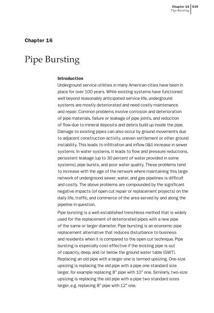
<strong>Chapter</strong> <strong>16</strong><strong>Pipe</strong> Bursting535<strong>Chapter</strong> <strong>16</strong><strong>Pipe</strong> BurstingIntroductionUnderground service utilities in many American cities have been inplace for over 100 years. While existing systems have functionedwell beyond reasonably anticipated service life, undergroundsystems are mostly deteriorated and need costly maintenanceand repair. Common problems involve corrosion and deteriorationof pipe materials, failure or leakage of pipe joints, and reductionof flow due to mineral deposits and debris build up inside the pipe.Damage to existing pipes can also occur by ground movements dueto adjacent construction activity, uneven settlement or other groundinstability. This leads to infiltration and inflow (I&I) increase in sewersystems. In water systems, it leads to flow and pressure reductions,persistent leakage (up to 30 percent of water provided in somesystems), pipe bursts, and poor water quality. These problems tendto increase with the age of the network where maintaining this largenetwork of underground sewer, water, and gas pipelines is difficultand costly. The above problems are compounded by the significantnegative impacts (of open cut repair or replacement projects) on thedaily life, traffic, and commerce of the area served by and along thepipeline in question.<strong>Pipe</strong> bursting is a well-established trenchless method that is widelyused for the replacement of deteriorated pipes with a new pipeof the same or larger diameter. <strong>Pipe</strong> bursting is an economic pipereplacement alternative that reduces disturbance to businessand residents when it is compared to the open cut technique. <strong>Pipe</strong>bursting is especially cost-effective if the existing pipe is outof capacity, deep, and/or below the ground water table (GWT).Replacing an old pipe with a larger one is termed upsizing. One-sizeupsizing is replacing the old pipe with a pipe one standard sizelarger, for example replacing 8” pipe with 10” one. Similarly, two-sizeupsizing is replacing the old pipe with a pipe two standard sizeslarger, e.g. replacing 8” pipe with 12” one.
536<strong>Chapter</strong> <strong>16</strong><strong>Pipe</strong> Bursting<strong>Pipe</strong> bursting conventionally involves the insertion of a coneshaped bursting head into an old pipe. The base of the cone islarger than the inside diameter of the old pipe and slightly largerthan the outside diameter of the new pipe to reduce friction andto provide space for maneuvering the pipe. The back end of thebursting head is connected to the new Polyethylene (PE) pipe andthe front end is attached to a cable or pulling rod. The new pipe andbursting head are launched from the insertion shaft and the cable orpulling rod is pulled from the pulling shaft, as shown in Figure 1. Thebursting head receives energy to break the old pipe from one of thefollowing sources: a pulling cable or rod, a hydraulic source, or an aircompressor. The energy breaks the old pipe into pieces and expandsthe diameter of the cavity. As the bursting head is pulled throughthe old pipe debris, it creates a bigger cavity through which the newpipe is simultaneously pulled from the insertion shaft. There aremany variations to this conventional layout that are presented laterin the chapter.History<strong>Pipe</strong> bursting was first developed in the UK in the late 1970s by D. J. Ryan & Sons inconjunction with British Gas, for the replacement of small-diameter, 3- and 4-inch castiron gas mains (Howell 1995). The process involved a pneumatically driven, coneshapedbursting head operated by a reciprocating impact process. This method waspatented in the UK in 1981 and in the United States in 1986; these patents expired inApril, 2005. When it was first introduced, this method was used only in replacing castiron gas distribution lines; it was later employed to replace water and sewer lines. By1985, the process was further developed to install up to <strong>16</strong>-inch outer diameter (OD)medium-density polyethylene (MDPE) sewer pipe. Replacement of sewers in the UKusing sectional pipes as opposed to continuously welded PE pipe was described in apaper by Boot et al. (1987). Up to 2006, approximately 9,000 miles of PE pipe has beeninstalled by bursting (Najafi, 2006). Currently, pipe bursting is used to replace waterlines, gas lines, and sewer lines throughout the world.
<strong>Chapter</strong> <strong>16</strong><strong>Pipe</strong> Bursting537ForceAir Pressure/HydraulicHose New HDPE <strong>Pipe</strong>InsertionPit DBurstingHeaddGround SerfacePullingPitOld <strong>Pipe</strong>Pulling Cable/RodD= Depth of cover d= Diameter of the existing pipeFigure 1 The <strong>Pipe</strong> Bursting Operation Layout<strong>Pipe</strong> Bursting and Trenchless <strong>Pipe</strong> Replacement SystemsExisting old pipes can be replaced by one of several trenchless techniques developedup to date. There are three basic methods of pipe bursting: pneumatic, hydraulic, andstatic pull. In addition, there are proprietary trenchless pipe replacement systems thatincorporate significant modifications to the basic pipe bursting technique. The basicdifference among these systems is in the source of energy and the method of breakingthe old pipe and some consequent differences in operation that are briefly describedin the following paragraphs. The selection of a specific replacement method dependson soil conditions, groundwater conditions, degree of upsizing required, type ofnew pipe, construction of the existing pipeline, depth of the pipeline, availability ofexperienced contractors, and so on.Pneumatic Bursting SystemsThe most common pipe bursting method is the pneumatic system. In the pneumaticsystem, the bursting tool is a soil displacement hammer driven by compressed airand operated at a rate of 180 to 580 blows per minute. It is similar to a pile-drivingoperation going horizontally. The percussive action of the hammering cone-shapedhead is also similar to hammering a nail into the wall; each hammer pushes the naila short distance as shown in Figure 2. With each stroke, the bursting tool cracks andbreaks the old pipe, the expander on the head - combined with the percussive actionof the bursting tool, push the fragments and the surrounding soil providing space topull in the new PE pipe. The expander can be frontend (attached to the frontend ofthe hammer) for pipes smaller than 12” or back-end (attached to the backend of thehammer) for pipes larger than 12”. The frontend expander allows withdrawing thehammer through the PE pipe after removing the expander from the existing manholeat the pulling shaft without damaging the manhole. The tension applied to the cablekeeps the bursting head aligned with the old pipe, keeps the bursting tool pressed
538<strong>Chapter</strong> <strong>16</strong><strong>Pipe</strong> Burstingagainst the existing pipe wall, and pulls the new PE pipe behind the head. An airpressure supply hose is inserted through the PE pipe and connected to the burstingtool. The bursting starts once (1) the head is attached to the new pipe, (2) the winchcable is inserted through the old pipe and attached to the head, (3) the air compressorand the winch are set at a constant pressure and tension values. The processcontinues with little operator intervention until the head reaches the pulling shaft atwhich point it is separated from the PE <strong>Pipe</strong>.Figure 2 The Bursting Head of the Pneumatic SystemStatic Bursting SystemsThe second common method of pipe bursting is the static pull system. In the staticpull system, a larger tensile force is applied to the cone-shaped expansion head
<strong>Chapter</strong> <strong>16</strong><strong>Pipe</strong> Bursting539through a pulling rod assembly or cable inserted through the existing pipe. The conetransfers the horizontal pulling force into a radial force -- breaking the old pipe andexpanding the cavity providing space for the PE pipe as shown in Figure 3. The steelrods, each is about four feet long, are inserted into the old pipe from the pullingshaft. The rods are connected together using different types of connections. When therods reach the insertion shaft, the bursting head is connected to the rods and the PEpipe is connected to the rear of the head. A hydraulic unit in the pulling shaft pullsthe rods one rod at a time, and the rod sections are removed. The process continuesuntil the bursting head reaches the pulling shaft, where it is separated from the PEpipe. If cable is used instead of rod, the pulling process continues with minimuminterruption, but the tensile force of a cable compared to a rod section is limited.<strong>Pipe</strong> SplittingThe North American Society for Trenchless Technology (NASTT) defines pipe splittingas a replacement method for breaking an existing pipe by longitudinal slitting. Atthe same time a new pipe of the same or larger diameter may be drawn in behind thesplitting tool (NASTT 2008). <strong>Pipe</strong> splitting is used to replace ductile material pipes,which does not fracture using the above-cited bursting techniques. The system hasa splitting wheel or cutting knives that slit the pipe longitudinally at two more linesalong the side of the pipe. An example of splitting head is shown in Figure 4.Figure 3 The Static Pull Bursting Head with Accessories to Cut Reinforcing Steel in RCP
540<strong>Chapter</strong> <strong>16</strong><strong>Pipe</strong> BurstingFigure 4 <strong>Pipe</strong> Splitting Head (PIM Corporation 2007)<strong>Pipe</strong> Reaming<strong>Pipe</strong> reaming is pipe replacement technique that uses a horizontal directional drilling(HDD) machine with minor modification. After pushing the drill rods through theold pipeline and connecting the rods to a special reamer (see Figure 5), the newPE pipe string is attached to the reamer via a swivel and towing head. As the drillrig rotates and simultaneously pulls back, the old pipe is grinded and replaced bythe new PE pipe. Removal of the old pipe is accomplished by mixing the grindedmaterial with the drilling fluid and transferring it to an exit point for removal viaa vacuum truck. Directional drilling contractors or utility contractors who use anHDD rig can add inexpensively modified reamers of various types for different pipematerials and ground conditions. <strong>Pipe</strong> reaming is limited to non-metallic pipelinereplacement. According to Nowak (Hayward 2002), the surrounding environmentalconditions (groundwater, sand, rock, concrete encasement, etc) that prohibit otherprocedures are not obstacles to successful installations.Figure 5 Reaming Head!Impactor ProcessThe patented Impactor process is another system that combines the HDD with pipebursting as shown in Figure 6. The bursting head (Impactor) receives air through theHDD stems. The HDD is connected to the air supply and positioned to drill out to anentry manhole. Then the HDD stem is pushed through old pipe to the next manhole
<strong>Chapter</strong> <strong>16</strong><strong>Pipe</strong> Bursting541and drilled back to the entry manhole. The Impactor device, after it is attached tothe drill stem and to the replacement pipe, is pulled into the old pipe. While pullingback, the Impactor system is activated and bursts the old pipe. The combined actions- of pulling using the HDD rig and of hammering of the Impactor device - breaksup the old pipe and replace it with the new pipe. The Impactor system can reduceexcavation and overcomes blocked old pipes.Figure 6 The Impactor Process Combines HDD with <strong>Pipe</strong> BurstingOld <strong>Pipe</strong> MaterialIn most bursting applications, the old pipe is made of a rigid material such asvitrified clay pipe (VCP), ductile iron, cast iron, plain concrete, asbestos, or someplastics. Reinforced concrete pipe (RCP) was successfully replaced when it was notheavily reinforced or if it was substantially deteriorated. The diameter of the old pipetypically ranges from 2 inches to 30 inches, although the bursting of larger diametersis increasing. A length of 300 to 400 feet is a typical length for bursting; however,much longer runs were completed with bursting systems that are more powerful.In addition, some point repairs on the old pipe, especially repairs made with ductilematerials, can make the process more difficult.New <strong>Pipe</strong> MaterialHigh-and medium-density polyethylene (HDPE and MDPE) have been the mostusedreplacement pipes for pipe bursting applications. The main advantages of PEpipe are its continuity, flexibility, and versatility. The continuity, which is obtained bybutt fusing together long segments in the field, reduces the possibility of stopping the
542<strong>Chapter</strong> <strong>16</strong><strong>Pipe</strong> Burstingprocess. The flexibility allows bending the pipe for angled insertion in the field. Inaddition, it is a versatile material that meets all the other requirements for gas, water,and wastewater lines. The smoother interior surface (relative to other pipe material)reduces the friction between the flow and the pipe wall, which allow higher flowspeed and increased flow capacity. The PE pipe does not erode, rotten, corrode, orrust; it also does not support bacteriological growth. The relatively higher thermalexpansion coefficients are the main issue with PE pipes, but when the PE pipe isinstalled and restrained appropriately, the pipe expands and contracts without anydamage. When used in pipe bursting applications, the friction between the soil andthe pipe is reduced.The internal surface of the PE pipe is smoother than those of the concrete or claypipes. For gravity applications, after some algebraic manipulation to the followingChezy-Manning equation, it is can be demonstrated that the flow capacity of the PEis 44% more than those of the concrete or clay pipes considering the internal diameterfor the old clay or concrete pipe equals that of the replacement PE pipe.!WhereQ = the flow quantityn = Manning roughness coefficientA = the area of the piper H = hydraulic radiusS = the slope of the energy line, which is parallel to the water surface and pipe invert if the flow is uniform.The n value ranges for clay or concrete pipes between 0.012 and 0.015 (on averageabout 0.013), and it is about 0.009 for PE (Lindeburg 1992).In addition to PE, other new pipe materials can be ductile iron, VCP, or RCP.However, these pipes cannot be assembled into a single pipe string prior to burstingoperation; but they can be jacked into position behind the bursting head or keptcompressed by towing them via a cap connected to the cable or rod that passesthrough the pipes. Therefore, the static pull system is the only bursting systemthat can be used with these pipes. The joints of these pipes must be designed fortrenchless installations.When is <strong>Pipe</strong> Bursting a Preferred Solution?For repair and replacement, conventional techniques have involved open cutexcavation to expose and replace the pipe. Alternatively, the pipeline can berehabilitated by inserting a new lining or replaced by pipe bursting. There are severalpipe lining technologies available such as cured in place pipe, deform and reform,
<strong>Chapter</strong> <strong>16</strong><strong>Pipe</strong> Bursting543and slip lining. The main advantage of the lining methods over pipe bursting is theneed for small or no access excavation to the pipeline. In contrast, pipe bursting hasthe advantage of increasing the pipe capacity by more than 100%.The unique advantage of pipe bursting over pipe lining techniques is the ability toupsize the service lines. A 15% and 41% upsizing doubles the capacity of the sewerand water lines respectively. The technique is most cost advantageous compared tothe lining techniques when (1) there are few lateral connections to be reconnectedwithin a replacement section, (2) the old pipe is structurally deteriorated, and (3)additional capacity is needed.For pressure applications, 41% increase in the inside pipe diameter double the crosssectional area of the pipe and consequently double the flow capacity of the pipe.For gravity applications, after some algebraic manipulation to the above-mentionedChezy-Manning equation, it shown that a 15% and 32% increase in the insidediameter of the pipe combined with the smoother pipe surface can produce a 100%and 200 % increase in the flow capacity, respectively.<strong>Pipe</strong> bursting has substantial advantages over open cut replacements; it is muchfaster, more efficient, and often less expensive than open cut especially in sewerapplications due to high depths that usually gravity sewer pipes are installed. Theincreased sewer depth requires extra excavation, shoring, and dewatering whichsubstantially increases the cost of open cut replacement. The increased depth hasa minimal effect on the cost per foot for pipe bursting as shown in Figure 7 (Pooleet al 1985). Specific studies carried out in the US have shown that pipe burstingcost savings are as high as 44% with an average savings of 25% compared to opencut (Fraser et al 1992). This cost saving could be much more if the soil is hardrock because rock excavation is extremely expensive compared to pipe bursting.Additionally, open cut can cause significant damage to nearby buildings andstructures (Atalah 2004).
544<strong>Chapter</strong> <strong>16</strong><strong>Pipe</strong> BurstingFigure 7 Cost Comparison Between <strong>Pipe</strong> Bursting and Open Cut Replacements(Poole et al 1985)In addition to the direct cost advantage of pipe bursting over open cut, pipe bursting,as a trenchless technique, has several indirect cost savings. Less traffic disturbance,road or lane closing, time for replacement, business interruption, and environmentalintrusion are some examples of these indirect cost savings. <strong>Pipe</strong> bursting has minimalinterference with other utilities, and less safety hazards (for both operators and thepublic) due to reduced open excavation.The unique advantage of pipe bursting over pipe lining techniques; such as curedin-placepipe (CIPP), sliplining, and deform and reform, etc.; is the ability to upsizethe service lines. A 15% and 41% upsizing doubles the capacity of the sewer andwater lines respectively. The technique is most cost advantageous compared to thelining techniques when (1) there are few lateral connections to be reconnected withina replacement section, (2) the old pipe is structurally deteriorated, and (3) additionalcapacity is needed. <strong>Pipe</strong> bursting has the following additional advantages over opencut: (1) minimal disruption to traffic, (2) minimal interference with other utilities, (3)superior safety (for both operators and the public) due to reduced open excavation,and (4) substantial time savings.<strong>Pipe</strong> Bursting Project ClassificationNational Association of Sewer Service Companies (NASSCO) classified burstingprojects into three classifications in terms of difficulty; they are A – routine, B -moderately difficult to challenging, and C – challenging to extremely challenging.The projects are classified as A - routine if the depth is less than 12 feet, the existingpipe is 4-12 inch in diameter, the new pipe is same size as the old pipe or onediameter upsize, the burst length is less than 350 feet, the old trench is significantly
<strong>Chapter</strong> <strong>16</strong><strong>Pipe</strong> Bursting545wider than the diameter of the new pipe, and the soil is compressible outsidetrench (soft clay, loose sand). The projects are classified as B - moderately difficultto challenging if the depth is between 12 feet and 18 feet, existing pipe is between12 to 20 inch, the diameter of the new pipe is two diameter upsize, the burstlength is between 350 feet to 450 feet, the trench width less than 4 inch wider thannew pipe diameter, or the soil is moderately compressible outside trench such asmedium dense to dense sand, medium to stiff clay. The projects are classified as C– Challenging to Extremely Challenging if the depth is more than 18 feet, existingpipe is between 20 and 36 inch, the new pipe diameter is three or more diameterupsize, the length is more than 450 feet, the soil is incompressible outside trench,or the trench width is less than or equal to upsize diameter. Note that the degree ofdifficulty increases as more than one of the above criteria applies (Najafi 2007).Table 1Summary of NASSCO <strong>Pipe</strong> Bursting ClassificationCriteriaA – Routine (all of thecriteria below apply)B - Moderately Difficult toChallengingC – Challenging toExtremely ChallengingDepth Less than 12 feet 12 ft to 18 ft More than 18 ftExisting <strong>Pipe</strong> 4”-12” 12” to 20” 20”-36”New <strong>Pipe</strong> DiameterSize for size or one diameterupsizeTwo diameter upsizeThree or more diameterupsizeBurst Length Less than 350 feet 350 feet to 450 feet More than 450 feetTrench WidthSoilRelatively wide trenchcompared to upsizeddiameterCompressible soils outsidetrench (soft clay, loose sand)Trench width less than 4”wider than upsize diameterModerately compressiblesoils outside trench (mediumdense to dense sand,medium to stiff clay)Incompressible soils (verydense sand, hard clay orrock) outside trenchConstricted trench geometry(width less than or equal toupsize diameter)<strong>Pipe</strong> Bursting Applicability and Limitations<strong>Pipe</strong> bursting is used to replace water lines, sewer mains, and gas lines, as wellas sewer lateral connections. Typical replacement length is between 300 feet and500 feet; however, in favorable conditions, longer drives have been completedsuccessfully. The size of pipes being burst typically range from 2 to 30”, althoughpipes of larger sizes can be burst. <strong>Pipe</strong> bursting is commonly performed size-forsizeand one-size upsize above the diameter of the existing pipe. Larger upsize (upto three pipe sizes) have been successful, but the larger the pipe upsizing, the moreenergy needed and the more ground movement will be experienced. It is importantto pay close attention to the project surroundings, depth of installation, and soilconditions when replacing an existing pipe especially in unfavorable conditionssuch as expansive soils, repairs made with ductile material, collapsed pipe, concreteencasement, sleeves, and adjacent utility lines.
546<strong>Chapter</strong> <strong>16</strong><strong>Pipe</strong> BurstingOn the other hand, pipe bursting has the following specific limitations: (1) excavationfor the lateral connections is needed, (2) expansive soils could cause difficultiesfor bursting, (3) a collapsed pipe at a certain point along the old pipe may requireexcavation at that point to allow the insertion of pulling cable or rod and to fixthe pipe sag, (4) point repairs with ductile material can also interfere with thereplacement process, (5) if the old sewer line is significantly out of line and grade,the new line will also tend to be out of line and grade although some corrections oflocalized sags are possible, and (6) insertion and pulling shafts are needed speciallyfor larger bursts.Design Considerations<strong>Pipe</strong>-bursting projects can be broken down to three phases: pre-design, design, andconstruction. The pre-design phase involves collecting information about the problempipeline, investigating the alternative solutions, and ensuring that pipe burstingis the best solution. The design phase involves investigating the conditions of theold pipe and trench, nearby utilities and structures, determining shaft locations,bypass pumping requirements, and developing detailed drawing and specifications.The construction phase involves selecting the bursting system, lateral connections,submittals, shaft construction and shoring, bypass pumping, and restoration.Pre-design PhaseAt the pre-design and design phases, the ability to influence the cost of the projectis the highest, and the cost of project modification is lowest, as shown in Figure 8.This is especially true for small jobs where the contractor’s cost savings (from designmodification) is small in magnitude, and the benefits do not justify the risk of beingresponsible for the redesign and its consequences. Therefore, invested effort in thisphase will pay dividends later.
<strong>Chapter</strong> <strong>16</strong><strong>Pipe</strong> Bursting547n10 1000990100008800 Project770concept0Feasibility660study0Design55004400Bidding3300Construction2200110000TIME0EINFLUENCE ONCONSTRUCTIONCOSTCOSTFigure 1 Ability to influence construction cost over time (Project Management <strong>Institute</strong>Inc. 2004)CONSTRUCTION COST %%Figure 8 Ability to Influence Construction Cost Over Time(Project Management Institue Inc. 2004)INFLUENCE ON ON COST COST %%The pre-design phase involves collecting information about the old and newpipelines. The designer determines the maximum flow requirements for the futuredesign life of the pipeline (considering the future economical developments andpopulation growth trends), and then calculates the diameter of the new pipe. Thisphase also includes investigating potential solutions for the problem and collectingthe relevant information to evaluate the valid solutions. For example, potentialsolutions may include installing another new line, lining the old pipe, replacing thepipeline via open cut, replacing it by pipe bursting, and so forth. If pipe bursting isthe optimal solution, the design team proceeds to the design phase.Many times open cut is the specified method of construction for most pipelineprojects, and the bursting contractors offer pipe bursting as an alternative to opencut. This process may include preparation and submittal of two bids: one is basedon open cut and the second is a value-engineering proposal based on pipe bursting.While this arrangement may increase the competition among bidding contractors,it increases the overall project cost (due to risk and contingency factors) for theproject because (1) while the presented information in the contract document mightbe complete for the open cut method, it may be incomplete for estimating the costof the bursting project and (2) this incomplete bid information increases the risk ofproblems during construction period that may lead to change orders and possibledisputes that are more costly to resolve. It is believed that if the owner and theengineer select the methods of construction (for example open cut and pipe bursting)early during the design phase, the competition is maintained, bidding information iscomplete, and the risk of changes is reduced as illustrated in Figure 8.
548<strong>Chapter</strong> <strong>16</strong><strong>Pipe</strong> BurstingDesign PhaseThe design phase starts with collecting further information about the old line, suchas: the type of soil and backfill, current flow volume for bypass pumping, lateralconnections, trench width, backfill compaction levels, and manhole locations. Thisphase also includes locating nearby utilities, investigating soil and trench backfillmaterial, and developing risk assessment plans. The feasibility of pipe burstingas the optimal solution may need to be re-evaluated in light of the new collectedinformation. The designer completes this phase with developing detailed drawingand specifications and complete bid documents which include listing of the neededsubmittals. The drawings should provide all relevant information, such as diameterand material type of existing pipe, existing plan view and profile, existing nearbyutilities and structures (crossing and parallel), repair clamps, concrete encasement,fittings, and so forth. This information is collect through a CCTV or similar inspectionof the old pipe.Utility SurveySurrounding utilities have significant impact on the success of the pipe burstingoperation, and the design engineer should attempt to identify and locate theseexisting utilities. However, the exact location of these utilities must be identifiedduring the construction phase through visual locating, such as vacuum potholing.The identification of nearby utilities by design engineer is critical for the followingreasons:• The presence of nearby utilities may steer the engineer to eliminate pipe bursting asa construction method.• The existing utilities may affect the location of insertion and pulling/jacking shafts.• Reduce or eliminate the risk of causing significant damage to these utilities.• The contractors need to know the number of utilities that they need to expose toaccount for them in their bid.• Consideration for protection of existing utilities from the ground movementof the bursting operation must be made early on to reduce the risk of serviceinterruptions to the customers.• Reduce the risk of injuries and fatalities to the workers and nearby people if theseutilities are accidently damaged during bursting.Site investigation should indicate the locations of many utilities; for example, sewermanholes indicate the presence of a sewer line and fire hydrants indicate the presenceof a water line, etc. The engineer should contact the One-Call center for utilitiesmarking, review the available as-built drawings from the different utility owners, andideally consider geographic information system (GIS) data (if available), utility maps,
<strong>Chapter</strong> <strong>16</strong><strong>Pipe</strong> Bursting549and conducts surface and subsurface investigations to superimpose these utilities onplans and profiles.Investigation of Existing <strong>Pipe</strong> and Site ConditionsInvestigation of the old pipe condition assists in selecting the suitable rehabilitationtechnique and provides the exact location of the lateral connections. The conditionsof the existing pipe may render pipe bursting as an unsuitable method for correctingthe problem. The presence of sags in the line may require treatment for the sag priorto bursting. The host pipe (diameter, material, and conditions) and the diameter ofthe new pipe guide the contractor to select the appropriate bursting system type, size,and accessories during the bidding and construction phase. The site conditions andsurface features may affect the locations of the insertion and pulling shafts, stagingarea for fused pipe, traffic control planes, and foot print for the needed burstingsystem components.Insertion and Pulling Shaft RequirementsWhen planning for shaft locations, the engineer identifies spots where excavation isneeded to replace manholes, valves, lateral connections, or fittings. These excavationspots are used as insertion or pulling shafts. However, if excavation at the manholelocation is not feasible or needed, shaft excavation at other locations may beconsidered. In selecting the location of these shafts, the engineer has to consider thefollowing issues:• Sufficient staging area for the fused replacement pipe to avoid blocking drivewaysand intersecting roads.• The shaft length should be long enough to allow alignment of the bursting headwith old line and for the PE pipe to bend safely from the entry point to the groundsurface.• Space for the construction equipments such as backhoe, loader, crane, etc.• Nearby flow bypass discharge spot or space to lay by pass lines without blockingdriveways and intersecting roads.• Traffic control around shafts.• Soil borings close to these shafts.• Discharge spots for dewatering if needed.• Using the same shaft to insert or pull pipes more than once.Generally, the engineer recommends locations for the insertion and pulling shaftbut leaves the final determination to the contractor (through a submittal process)with the guidelines of minimizing excavation and disturbance to the surroundingenvironment.
550<strong>Chapter</strong> <strong>16</strong><strong>Pipe</strong> BurstingSoil Considerations in <strong>Pipe</strong> BurstingThe soil and subsurface investigation is collecting the necessary information toproperly design the project. It assists the contractor in submitting a proper bid byselecting the appropriate bursting system (type and size), shoring of the pulling andinsertion shafts, dewatering system, compacting backfill material, etc. This properdecisions and biding increase the chances of success during the construction phase ofthe project.The soil investigation activities include soil borings, standard penetration tests,groundwater level determinations, trench geometry investigation, and native soil andtrench backfill material classifications. If the presence of washouts or voids aroundthe existing pipe is suspected, Ground Penetrating Radar (GPR) survey may assistin determining locations and magnitude of these voids. Special attention should begiven to the presence of major difficulties that may render pipe bursting not feasiblesuch as the presence of rock, hard cemented dense soils, very soft or loose soils,reinforced concrete encasement, very narrow trench in hard soils or rock, or ductilepoint repairs. If contaminated soil is suspected, the type and extent of contaminationshould be identified and indicated in the contract documents. The contractorshould be requested to take the necessary measures to handle and dispose of thiscontaminated soil.The soil around the pipe (backfill and native soil) has to be compressible to absorb thediameter expansion. Compressible soils are the ideal soils for pipe bursting becausethe outward ground displacements will be limited to an area surrounding the pipealignment as shown in Figure 9. Original backfill is the most suitable soil for burstingfollowed by (increasing difficulty) compressible clay, loose cobble, beach and runningsand, densely compacted clay, then sandstone. Soils with long standup time allowthe overcut (created by the expanded hole) to remain open for most of the burstingoperation, thus reducing the friction force between the soil and the pipe. The overcutlowers the needed pulling forces and consequently the axial stress on the new pipeduring installation. Somewhat less favorable ground conditions for pipe burstinginvolve densely compacted soils and backfills, soils below the water table andexpandable soils. Special soils such as highly expansive soils or collapsible soils willalso cause problems.<strong>Pipe</strong> bursting below the groundwater table increases the difficulty of the burstingoperations because the groundwater flows towards the insertion shaft requiringdewatering of the shaft. Also, in very soft or loose soils, significant groundmovements may take place causing significant sags in the new line and damageto nearby structures. In sever situations, the soils particles migrate to the old pipeconverting the bursting operation into a piercing operation. If the groundwater islowered via any dewatering technique such as deep wells, well point system, or opensumps in the pulling and receiving shafts, the effective soil pressure will increase.
<strong>Chapter</strong> <strong>16</strong><strong>Pipe</strong> Bursting551This will increase the vertical loads on the pipe causing increased friction, burstingand pulling force, and tensile stresses in the PE pipe. On the other hand, the presenceof water reduces the coefficient of friction between the pipe and the soil, reducing theapplied pulling force.If the original soil borings (during the old pipe installation) are available, they shouldbe reviewed and made part of the supplemental information available to the bidders.The determination of the trench geometry and backfill material and compaction isimportant for the designer and contractor.Maximum Allowable Operating Pressure (MAOP)For pressure applications such as water, gas, and force mains, the maximumallowable pressure should be determined based on the maximum surge pressurethat pipe will be subject to and the maximum operating pressure for the pipe. The PEpipe should be designed to withstand the maximum allowable operating and surgepressures according to the design procedure shown in <strong>Chapter</strong> 6 in this Handbook.DR 17 is typically used for bursting pressure or gravity pipe unless a higher pressurerating is required. In short bursting runs where high tensile forces are not expectedDR 21 can be used.Risk Assessment PlanMost underground and pipeline construction projects generally have some risksassociated with the unknown subsurface conditions. The risks associated withpipe bursting include damage to nearby utilities and structures, failure to completethe project using pipe bursting, and time and/or budget overrun. There is risk ofdamage to nearby utilities, buried structures, and pavement if there are adverse soilconditions, improper construction techniques, design mistakes, inappropriate toningof utilities, etc. There are also many risks associated with flow bypass, dewatering,shoring, etc if the appropriate procedures were compromised. A list of additionalrisks that may stop the bursting operation and/or create problems include:• Settlement at insertion/pulling pits if the density of the backfill exceeds that ofnative soil.• Bursting through sharp curves.• Concrete encasement or steel point repair inside existing pipe.• Excessive bursting lengths.• Damage to new pipe from sharp edge or fragments of existing pipe beingburst/split.• Damage to laterals from bursting of main line.
552<strong>Chapter</strong> <strong>16</strong><strong>Pipe</strong> Bursting• The presence of rock under the existing pipe may create a ‘bump’ in thereplacement pipe.• Collapsed pipe.Projects with class C classification-challenging to extremely challenging as indicatedin Table 1- must be carefully examined in terms of required forces and grounddisplacements. Additionally, the depth of the old pipe affects the expansion ofsurrounding soil and consequently the extent of ground displacement around thepipe. If the pipe is shallow, damage to the pavement may take place. Saw cutting thepavement prior to bursting might be advisable. If the existing pipe is below the GWT,the difficulties increase. Insertion and pulling shafts grow larger and more complexas the depth increases.If there are unacceptable sags in the existing sewer line, these sags need to becorrected before bursting. The sags can be corrected by local excavation, surfacegrouting, or grouting from within the pipe. Some reduction of sag magnitude may beexpected (without corrective measures) from the bursting operation, but the extent towhich the problem is corrected depends on the relative stiffness of the soil below thesagging section.If there is erosion of the soil around the pipe, the bursting head and the following PEpipe will tend to deviate toward the void or lower density region. If there is a hardsoil layer or rock close to the pipe, the bursting head will tend to displace towardsthe softer soil. In shallow conditions, the bursting head will deviate mostly upwardstowards the ground surface. If the conditions change substantially along the lengthof the burst, this may cause some change in the grade and/or alignment of the pipe.When the grade is critical, these possibilities should be considered.Most pipe bursting operations can be done safely if site and project conditionsare known before bursting and appropriate measure are taken to address theseconditions. There are well known solutions to all of the above mentioned risksand problems, and successful project engineers or construction managers identifythese risks and develop a risk management plan to address these specific risks forthis project. This plan includes quantification of the occurrence probability of theidentified events and their associated impact or damage; it also includes measures toeliminate, mitigate, transfer, or undertake these risks. One of the general measuresto mitigate the project risks is building and maintaining cooperative relationshipsamong owners, engineers, contractors, equipment manufacturers, and pipe suppliers.Identifying and developing a realistic plan to manage and share risks appropriatelyis an important part of effectively communicating responsibilities, defining roles,and building a strong team. It is important to pay close attention to the projectsurroundings (surface and subsurface conditions) for unfavorable conditions and
<strong>Chapter</strong> <strong>16</strong><strong>Pipe</strong> Bursting553risks. These conditions require extra attention in order to ensure the safety of allinvolved people as well as surrounding facilities and infrastructure.Ground Movement Associated with <strong>Pipe</strong> BurstingThe pipe bursting process creates a cavity in the soil around the pipe where the newpipe is pulled through. This cavity creates a compression plastic zone around the newpipe outlined by an elastic zone as shown in Figure 9.Figure 9 Cavity Expansion and the Plastic and Elastic Zones!The magnitude of the compression and the dimensions of these zones correlate withthe amount of upsizing, the diameter of the pipe, and the type of soil (Atalah 1998).The author investigated the ground movements and vibrations associated withbursting small diameter pipes in soft soils (Atalah 1998) and with large diameterpipes in rock conditions (Atalah 2004) and developed guidelines for safe distancefrom existing nearby utilities, structures, and pavement. Large diameter burstingin rock conditions is applicable for upsizing 24” in diameter reinforced RCP pipeswith upsize percentage less than 50%. Small diameter bursting in soft soils refersto upsizing 8” and 10” in diameter VCP with upsize percentage less than 30%. Thefindings of these reports are summarized in Figure 10.
554<strong>Chapter</strong> <strong>16</strong><strong>Pipe</strong> BurstingFigure 10 compares the peak particle velocity (PPS) of the soil versus the distancefrom the source of the vibration for different types of construction equipmentand small diameter pipe bursting in soft soils and large diameter bursting in rockconditions. The PPS is the velocity of soil particles as they vibrate due to theseconstruction activities. There is a strong correlation between the distance from thebursting head and the level of vibration for pneumatic bursting. As shown in Figure10, the bursting vibration levels quickly fall to levels that do not cause damage tobuildings. For structurally sound residential buildings, a safe distance (away fromthese structures) of eleven feet and eight feet are recommended for large diameterbursting in rock conditions and small diameter bursting in soft soils respectively.Safe distances of eight feet and four feet from nearby structurally sound commercialstructures are recommended for bursting large diameter bursting in rock conditionsand small diameter bursting in soft soils respectively. In addition, the statisticalanalysis indicates that the safe distance should be more than 7.5 feet from the buriedstructures. These pipes are mostly deep main lines installed in the right of way, whichare usually far from the residential or commercial buildings.
<strong>Chapter</strong> <strong>16</strong><strong>Pipe</strong> Bursting555Figure 10 The Attenuation Lines of the PPS Versus Distance from the Source for DifferentConstruction Pieces of Equipment (Wiss 1980) and the Attenuations of the 90%PI Upper Limit lines for the Pneumatic Bursting in Soft Soils (Atalah 1998) andHard Soils (Atalah 2004).
556<strong>Chapter</strong> <strong>16</strong><strong>Pipe</strong> BurstingPlans and SpecificationsThe contract documents typically include the contract agreement, general conditions,special conditions, project plans, specifications, geotechnical report, and CCTVrecords. The plans and specifications for pipe bursting projects should have all therequired information for typical open cut water or wastewater pipeline projects plusthe information listed in this section. The drawings should provide information aboutthe existing site conditions and the required construction work. Description of siteconstraints (i.e., work hours, noise, etc.) and the procedures to review the CCTV datashould be listed in the notes section in the drawings. The plans may also includeinformation to show erosion and sediment control requirements, flow bypassingplans, and service connection and reinstatement details. Generally the plans shouldinclude:• Limits of work; horizontal and vertical control references.• Topography and survey points of existing structures.• Boundaries, easements, and rights-of-way.• Existing utilities, sizes, locations, and pipe materials.• The verification requirements for existing utilities.• Plan and profile of the design alignment.• Existing point repairs, encasement, sleeves, etc.• Construction easement and the allowable work areas around the insertion andpulling pits.• Details for lateral connections and connections to the rest of the network.• Restoration plans.• Traffic control plans.• Existing flow measurements for bypass pumping (Najafi 2007).The technical specifications supplement the drawings in communicating the projectrequirements. Information to be included in the technical specifications shouldinclude:General• Minimum contractor qualifications.• Permit matrix and responsibilities.• Safety requirements with focus on confined space entry, flow bypass, and shoring.• Scheduling requirements and construction sequence.• Submittals.
<strong>Chapter</strong> <strong>16</strong><strong>Pipe</strong> Bursting557<strong>Pipe</strong> and Manhole Materials• Standards and tolerances for materials, wall thickness and class, testing andcertification requirements.• Construction installation instructions for pipe joining and handling.• Fittings, appurtenances, and connection-adaptors.• Acceptable material performance criteria and tests.Construction Considerations• Flow bypassing, downtime limits, and service reinstatement requirements.• Spill and emergency response plans.• Traffic control requirements.• Erosion and sediment control requirements.• Existing conditions documentation (e.g., photographs, videos, interviews).• Protection plan for existing structure and utility (ground movement monitoring).• Accuracy requirements of the installed pipe.• Daily construction monitoring reports.• Field testing and follow-up requirements for pipe joining, pipe leakage,disinfection, backfill, etc.• Site restoration and spoil material disposal requirements (Najafi, 2007).SubmittalsIn addition to the submittals needed for a traditional open cut projects, thesubmittals for pipe bursting projects usually include the following submittals: sitelayout plans, sequence of bursting, shoring design for all the excavations, bypasspumping plan, manufacturers’ specifications of the selected bursting system and itscomponents, dewatering plan, new pipe material, lateral connections material andplans, site layout plans, and so forth. The site layout plans would show the locationof the insertion and pulling shafts, dimensions of shafts, traffic flow, safety andcommunication plan, storage space to store and lay the new pipe, and so forth. Lastly,the site restoration and clean-up plans should be included in the submittalsQuality Control/Quality Assurance IssuesThe project specifications should state the quality control and assurance measuresrequired to ensure that the project is executed according to the contract specifications.In addition to the quality control and quality assurance measures usually specifiedfor a traditional open cut projects, there are a few measures that are specific tothe pipe bursting operations. The project specifications should state the qualitycontrol and assurance measures required to ensure that the project is executedaccording to the contract specifications. These measures can take the form of tests,
558<strong>Chapter</strong> <strong>16</strong><strong>Pipe</strong> Burstingcertifications, inspection procedures, etc. Extensive listing of the relevant requiredsubmittals, careful preparation of the submittals, and alert review and approval ofthe submittal are significant steps in the QC/QA program. The QC/QA programstates the performance criteria for the product line and the acceptable tolerancefrom these criteria. For example, the invert of the new pipe should not deviate fromthe invert of the old pipe by more than a certain number of inches, the depth ofsags in the line should not exceed one inch, and the difference in the vertical andhorizontal dimensions of the new pipe diameter should not exceed 2%. The QCprogram should state how these performance criteria will be measured, tested, andchecked. Some of these performance criteria that can be specified are post burstingCCTV inspection, pressure tests, and mandrel test. The surface and subsurfacedisplacement-monitoring program should be outlined in the specifications along withthe acceptable amount of ground movements. Certifications from the manufacturersof the bursting system, replacement pipe, and other material that these productsmeet the contract specifications based on tests conducted by the manufacturer ora third party may be required. For challenging projects, the presence of burstingsystem manufacturer representative at the jobsite may be required. The owner’squality assurance program should ensure that the field and management team of thecontractor have the knowledge and the experience needed to complete the projectsuccessfully and able to respond appropriately to unforeseen problems.Dispute Resolution MechanismsThe contract should include different site conditions and unforeseen conditionsclauses that allow contract time and amount adjustment if the conditions at sitematerially differ from the conditions expected and indicated in the bid documents.These clauses facilitate resolving disputes efficiently and quickly without negativeimpact on the project. If site conditions are significantly different than those describedin the contract documents and the contractor or owner can show that the differentconditions impacted the work, the contract value and duration should be adjustedaccordingly. Conducting the proper surface and subsurface investigations, outlinedearlier in this chapter, should minimize the occurrence of project disputes andpossibility of work stoppage during the pipe bursting operations.Maximum Allowable Tensile PullAfter the bursting head breaks the old pipe and creates a cavity in the ground, thewinch pulls the new pipe through this cavity. For the pipe to be pulled, the pullingforce has to exceed the friction between the outside surface of the pipe and thesurrounding soils. When the coefficient of friction between soil and the pipe is highand the outside surface area of the pipe is large, high pulling forces are neededto overcome this high friction resistance. The high pulling force generates hightensile stresses on the replacement pipe. If the allowable tensile strength of the pipe
<strong>Chapter</strong> <strong>16</strong><strong>Pipe</strong> Bursting559is less than the anticipated tensile stresses on the pipe, actions to reduce frictionmust be adopted to avoid excessive strains in the pipe. Examples of these actionsare increasing the diameter of the bursting head by about an inch to create abouthalf an inch of overcut around the pipe, and injecting bentonite and/or polymerlubrication into the annular space behind the bursting head to reduce the frictionalforces. If these actions are not sufficient to rectify the problem, shorter burstingrun and relocation of the insertion or pulling shafts must be considered. Frictionforce calculations need to be conducted before bursting operation starts to avoidover stressing the pipe. It is much easier and less costly to incorporate the abovementionedcorrective actions before bursting than during bursting.Typical safe pull tensile stress values for MDPE and HDPE are given in Table2. Consult the manufacturer for specific applications. The values are given as afunction of the duration of continuous loading. For pipe temperatures (not outsideair temperatures) other than 73ºF, multiply the value in Table 2 by the temperaturecompensating multipliers found in Table B.1.2 of the Appendix to <strong>Chapter</strong> 3. TheSafe Pull Load at 12 hours is given for many pipe sizes and DR’s in <strong>Chapter</strong> 12,Tables 4 and 5 (3xxx material) and Tables 6 and 7 (4xxx material).Table 2Safe Pull Tensile Stress @ 73ºFTypical Safe Pull Stress (psi) @ 73ºFDuration (Hours) PE2xxx (PE2406) PE3xxx (PE3408) PE4xxx0.5 1100 1400 15001 1050 1350 140012 850 1100 115024 800 1050 1100Note: The safe pull stress is the stress at 3% strain. For strains less than 3% the pipe will essentially havecomplete strain recovery after pullback. The stress values in Table 2 were determined by multiplying 3% times theapparent tensile modulus from the Appendix to <strong>Chapter</strong> 3 adjusted by a 0.60 factor to account for the high stresslevel during pullback.Estimating the pulling force to break the old pipe and overcome friction resistancebetween the new PE and the surrounding soil is very difficult and currently thereis no accurate method to calculate it. Many site and project factors interact to makedeveloping an accurate and reliable model very difficult; among these factors: thestrength of the old pipe, the type of backfill material, the type of native material,degree of upsize, bursting system, the amount of overcut, the presence of sags alongthe line, etc. Comparisons between the actual pulling forces and the calculated forcesusing the Terzaghi’s Silo Theory that is used in calculating the jacking force in pipejacking operations is presented later in this chapter.
560<strong>Chapter</strong> <strong>16</strong><strong>Pipe</strong> BurstingAtalah et al (1998) instrumented two PE pipe with strain gauges and measured thestrain in the pipe due to the pipe bursting process. They also calculated the frictionresistance between the pipe and the soil using Terzaghi’s silo theory. Figure 11presents a comparison between the maximum stresses recorded in the pipe againstcalculated pipe stresses. The stress was calculated on the basis that the soil collapsedaround the pipe and exerted a normal pressure on the pipe related to its depth belowthe ground surface similar to the frictional drag on jacking pipe. The assumptions forground pressure and frictional resistance followed the typical assumptions for pipejacking calculation presented in Atalah 1994 and Atalah 1996.Figure 11 Actual Stress vs. Calculated Stress for TTC Test Site #1 and 3As shown in the Figure 11 in TTC test site 1, there was substantially less frictionaldrag on the pipe than would be expected from a fully collapsed soil around the pipe.This indicated that the hole remained at least partially open during the replacementprocess. The cavity around the pipe stayed open during and possibly after thebursting because the nominal overcut was about 0.7 inch and the hammering actionof the head compressed the surrounding soil. For the TTC test site 3, the measureddata correlated well with the stresses that were generated from a collapsed soilaround the replacement pipe over its full length. It is not clear why the friction onthe pipe in this test is so much more than on the pipe in TTC Test Site #1 whichhad a larger upsizing. The following are the conclusions from these pipe stressmeasurements:• Appear to match the range of stresses measured• Measures to retard the collapse of soil around the replacement pipe will lowerstresses in the replacement pipe
<strong>Chapter</strong> <strong>16</strong><strong>Pipe</strong> Bursting561• None of the stresses measured exceeded about two-thirds of the yield stress of thePE pipe• The level of stress in the replacement pipe was actually less for the pipe withlarger upsizing percentage so there is not a direct relationship between upsizingpercentage and replacement pipe stress• The magnitude of the stress cycling in the replacement pipe during installation issmall compared with the mean stress levelThe pulling force must overcome the penetration resistance at the bursting head andthe friction resistance along the outside surface of the pipe. The friction equals theoutside surface area of the pipe times the soil pressure on the pipe times the frictioncoefficient between the soil and the pipe surface. A more detailed discussion aboutestimating the jacking force on jacking pipes is presented in Atalah 1994 and 1996.The frictional resistance, R, is calculated as follows:R = µ Vwhereµ = coefficient of friction.V = the force perpendicular to the contact surface calculated using the Terzaghi’s Silo TheoryThere are two techniques to reduce the pulling force through the pipe: oversize cutand lubrication of the outside surface of the pipe. Oversize cut at the face reduces thepuling force if the soil is highly stable. In unstable soil, oversize cut must be madenevertheless to allow lubricating the outside surface of the pipe, but it should beminimized. Lubrication around the whole perimeter of the pipe and along the wholelength of the drive significantly reduces the friction resistance.Permitting IssuesPermits from all the affected parties should be secured before the start of the burstingphase. Some of these permits could be secured by the owner and its representatives,and rest should be secured by the contractor. The permits responsibilities should beoutlined in the specifications and stated on the drawings. Permits to burst under theroad and to modify the regular traffic flow according to the project traffic control planshould be secured from owner of the affected road if the pipe crosses underneatha road. If the pipe crosses underneath a runway, taxiway, drainage ditch, irrigationchannel or canal, and railroad track, permits should be secured from the ownersof these facilities. Communications with the affected residents should take placebefore bursting to inform them about road closures, night or weekend work, servicedisruptions, driveway blockings and so on.
562<strong>Chapter</strong> <strong>16</strong><strong>Pipe</strong> BurstingTypical Bidding Form For a <strong>Pipe</strong> Bursting ProjectIn addition to providing the owner with the total price of the project to comparethe different bids, the bid form should provide the contractor and the owner witha mechanism for fair pricing and payment system based on the progress duringconstruction. The unit prices in the form can also be used to resolve disputesamicably. It is recommended that the bursting is measured in linear feet andsegmented by classification or sections from manhole to manhole or from insertionto pulling shaft. Segmentation by run or bursting class provides the owner and thecontractor with fairer pricing mechanism and reduces and resolves disputes.Table 3 shows an example of a typical bid form for a pipe-bursting project (Bennettand Ariaratnam 2005).Table 3Example of <strong>Pipe</strong> Bursting Bid Form (Bennett and Ariaratnam 2005)Item No. Description Quantity Unit1 Mobilization/Demobilization LS2 <strong>Pipe</strong> Cleaning and Pre CCTV Inspection LF3 <strong>Pipe</strong> Bursting of Exist. 6” VCP with New 9.05” O.D., SDRLF17 PE <strong>Pipe</strong> (4’-8’ Deep) from MH 1 to MH 64 <strong>Pipe</strong> Bursting of Exist. 12” Class 250 Cast Iron <strong>Pipe</strong> withLFNew 21.6” O.D. PE <strong>Pipe</strong> (8’-12’ Deep)5 <strong>Pipe</strong> Bursting of Exist. 24” RCP with New 30” VCP (12’-<strong>16</strong>’LFDeep) from MH 10 to MH <strong>16</strong>6 <strong>Pipe</strong> Bursting of Existing 4” Service Lateral with New 4.5”LFO.D., SDR 17 PE <strong>Pipe</strong> (4’-8’ Deep)7 4” Lateral Connection to 9.05 O.D. SDR 17 PE <strong>Pipe</strong> (8’-12’EADeep)8 6” Lateral Connection to Exist. MH EA9 New PE <strong>Pipe</strong> Connection at MH EA10 Furnish & Install 48” Dia. MH EA11 Manhole Renewal VF12 Cleaning, Testing and Post CCTV of New Sewer LS13 Replacement of Unsuitable Trench Backfill Material LS14 Bypass Pumping LS15 Traffic Control LS<strong>16</strong> Pavement, Sidewalk and Curb Installation LS17 Landscaping and Surface Restoration on Private Property LSUnitpriceTotalPricePlease note that the lateral connections are accounted as a separate bid items andsegmented by depth. Cleaning, testing, and post CCTV of the sewer line is a separatebid item. By pass pumping can be priced as a lump sum or measured by each run.
<strong>Chapter</strong> <strong>16</strong><strong>Pipe</strong> Bursting563Selection of <strong>Pipe</strong> SDRThe PE pipes are available with iron pipe sized (IPS) or ductile iron pipe sized (DIPS)outside diameters. PE pipes are extruded with fixed outside diameter with variancein the inside diameter controlled by the Standard Dimensional Ratio (SDR) as shownin following equation:!The PE pipe should withstand the internal pressure requirements of the water orthe force main line, overburden dead and live loads, and pulling forces during thebursting phase. The SDR of the PE pipe is a major factor in the ability of the pipe towithstand the installation forces and service pressures. Experience has shown thatSDR 17 is sufficient for gravity sewer applications, and thinner wall pipes with SDRof 19 or 21 can be used in shorter and smaller diameter applications. Thinner wallpipes tend to stretch excessively during bursting. For pressure applications, if themaximum allowable design pressure is less than 100 psi, SDR of 17 is sufficient. Ifthe maximum allowable design pressure is more than 100 psi, the allowable pressuregoverns the needed SDR. If the allowable pressure is 150 psi, PE pipe with SDR 11meets needed pressure requirements.In most trenchless applications, but not always, the pipe that withstands the pullingstresses during installation can withstand the vertical overburden and trafficpressures. The pipe stresses caused by construction are higher than those caused byvertical pressures. However, each application is different; it is possible that a specificapplication can require a different SDR. An engineering analysis is suggested for verydeep or very shallow installations. Deep installations may be subject high overburdenpressures, and shallow installations may be subject to high concentrated traffic loadsthat the pipe has to withstand.Section 2 of <strong>Chapter</strong> 6 in this Handbook presents how to calculate the live loads onthe pipe and stress distribution of live load with depth using the Timoshenko andBoussinesq equations to calculate the live load at the centerline of the pipe. The overburden pressure in trenchless applications can be calculated using the Terzaghi’s SiloTheory.Terzaghi’s Silo TheoryTerzaghi established a calculation model to estimate the normal pressure acting onthe pipe from vertical load and soil arch action. Terzaghi’s theory presents the loadon the pipe in a similar form to that of the horizontal earth pressure theory. Thefollowing equation gives the normal pressure on the pipe (P) as a function of soil
564<strong>Chapter</strong> <strong>16</strong><strong>Pipe</strong> Burstingdensity (w), depth of cover to center-line of the pipe (H), vertical live load at the pipelevel (PL) and coefficient of soil load (k).P = k (wxH + P L)The coefficient of soil load (k)whereK = soil lateral pressure coefficientδ = angle of wall friction between pipe and soilB = the influence width above the pipe.!According to the German Association for Water Pollution Control (ATVA <strong>16</strong>1), thevalues of these variables are: K = 0.5, δ = 0.5F (angle of internal friction of soil) andB= 1.73d (the outside diameter of the pipe). Figure 12 presents the value of k as afunction of F and the ratio H/d for K= 0.5. On the other hand, in Japan, K= 1, δ= Fand b= δ (0.5+tan(45-F/2) are used in the above equation. Although ground waterdoes not significantly influence the soil friction, the ATVA <strong>16</strong>1 specifies, for safetyreasons, that the full soil load should be applied in case of jacking below the groundwater table. If the surrounding soil is swelling soil, additional swelling pressure mustbe considered (Stein 89).
<strong>Chapter</strong> <strong>16</strong><strong>Pipe</strong> Bursting565Figure 12 Reduction Factor k According to ATVA <strong>16</strong>1Construction ConsiderationsOnce the owner issues the notice to proceed, the contractor prepares the submittalsfor the project according to bid documents. Typically, the contractor takes thefollowing steps:• Pre-construction survey• Cleaning or pigging of line, if needed• Closed circuit TV inspection, if needed• Excavations at services for temporary bypass• Setting up temporary bypass or connections to customers• Excavation of insertion and pulling shafts• Fusion of PE• Setting up the winch or hydraulic pulling unit and insertion of pulling cable orpulling rods inside the old pipe.• Installation of hoses through the PE pipe to attach to bursting head (air supplyhoses or hydraulic hoses for pneumatic or hydraulic systems respectively)
566<strong>Chapter</strong> <strong>16</strong><strong>Pipe</strong> Bursting• Connection of bursting head to pulling cable or rod• <strong>Pipe</strong> bursting and replacement with new pipe• Removal of bursting head and hoses from the pipe• Post installation inspection• <strong>Pipe</strong>line chlorination if it is not pre-chlorinated (for water mains)• Reconnection of services and reinstating manhole connections• Site restorationButt fusion of PE replacement pipe is typically carried out prior to the burstingoperation, so that all fused joints can be chlorinated (for water lines), checked, andtested. The pipe should not be dragged over the ground, and rollers, pipe cutouts,or slings should be used for both insertion and transportation of the pipe. The endsof water or gas pipes should be capped to prevent the entry of contaminants intothe pipe.Typical <strong>Pipe</strong> Bursting Operation LayoutThe first step in planning the pipe bursting operation is the optimization of thelocations of the insertion and pulling shafts by using the insertion shafts to insert thenew pipe into two directions. This optimization reduces the amount of excavation,mobilization, and demobilization efforts. These shafts should be planned at manholesor lateral connections in sewer lines and at fire hydrants or gate valves in waterapplications. The length of the run between the insertion and pulling shafts shouldnot generate friction forces that exceed the capabilities of the bursting system andthe tensile strength of the pipe. The next step is ensuring that the area around everyshaft is sufficient for safe operation of the needed pieces of equipment and materialstaging. The insertion shaft has a flat section and sloped section; the flat portion hasto be long enough to allow aligning the centerlines of the bursting head with thatof the old pipe. The slopped section has to be long enough to allow the PE pipe tobend without any negative impact on the pipe (i.e. accommodate the bending radiusrequirements of the pipe). PE pipes can be cold bent to a radius of 25 to 30 times theOD of the pipe depending on its SDR. Because of the pipe’s ability to bend, the laydown area of the pipe prior to insertion does not necessarily have to be in line withthe existing pipe. For example for an 18” PE pipe with an SDR of 17, the minimumlength of the insertion shaft is a horizontal length of 12 times the diameter of the newpipe (18 feet) plus a sloped length of 2.5 times the depth of the shaft as shown inFigure 13 (Bennett and Ariaratnam 2005). The width of the pit depends on the pipediameter and required working space around the pipe. The pulling pit must be largeenough to allow for operation of the winch or pull-back device, along with removalof the bursting head.
<strong>Chapter</strong> <strong>16</strong><strong>Pipe</strong> Bursting567Polyethylene Liner2.5 XD12 x dWinch AssemblyDExisting <strong>Pipe</strong> with CrownRemoved to spring lineD = Depth to invertd = Diameter of liner pipeFigure 13 Insertion Shaft Dimensions for PE <strong>Pipe</strong> with SDR 17 (Bennett and Ariaratnam 2005)Acceptable arrangements for traffic control, based on DOT and local governmentregulations, and for stretching the fused PE pipe with minimum inconvenienceto nearby residents and businesses must be carefully considered. The flow bypasspumping and pipes layout should be also planned and considered. If dewateringneeds arise, safe and proper flow discharge plans are required. The contractorsubmits the jobsite layout plan that reflects the intended method of construction andaddresses the above mentioned considerations. The contractor does not start burstingbefore the engineer reviews and approves the jobsite layout plan, and the siteinspector enforces the adherence to this plan unless there is a reason for the deviationapproved by engineer or owner. If contaminated soil is excavated, the contractorshould take the necessary measures to handle and dispose of this contaminated soil.Shoring The Insertion and Pulling Shafts.Proper shoring of the insertion and pulling shafts is essential for the safety ofthe workers and the safety of the surrounding environment. The trench shoringor bracing should be constructed to comply with OSHA standards. Some of theavailable means of shoring these shafts are: trench box, solder pile and lagging,steel sheet piles, corrugated pipes, etc. Also, if space is available, sloping the sidesof the shaft to provide stability is an option. The judgment and the supervision ofa competent person (as defined by OSHA) or a qualified geotechnical engineer isneeded to ensure safe shoring.In the pulling shafts, the winch will thrust against manhole wall or one side of thepulling shaft. This side has to be able to withstand the pressure coming from thepulling winch. Therefore, a thrust block or structure is needed to distribute the forceover a larger area. In the static pull applications, the contractor should construct a
568<strong>Chapter</strong> <strong>16</strong><strong>Pipe</strong> Burstingthrust block against which the pulling system thrusts during pulling and bursting.The thrust block, shoring, and soil behind the shoring must be able to withstand thestresses from the pulling system. The passive earth pressure of the soil has to exceedthe stresses generated by the pulling system with an acceptable factor of safety.Matching System Components to Reduce Risk of FailureOne of the most critical activities before bursting is to ensure that the bursting systemhas sufficient power to burst the old run from the insertion shaft to the pulling shaft.The system must be able to overcome the friction between the soil and the outsidesurface of the new pipe and the soil with reasonable margin of safety to overcomeunforeseen repair sleeves, clamps, etc.The contractor should adhere to the sizing guidelines stated in the operations manualissued by the bursting system manufacturer to match the system with the needsof the job. The bursting system manufacturer should be consulted if there is anydoubt regarding the adequacy of the system for that specific run in that particularconditions (soil, depth, type of pipe, etc.). Lubricating the outside surface of the pipewith polymer or bentonite (depending on the type of soil) can dramatically reducethe coefficient of friction between the pipe and the soil, and consequently, reducethe needed pulling force. In addition, the bursting system components should beappropriately matched to the need of the project; for example, the winch capacity ismatched with the bursting head size and the conditions of the job.Toning for UtilitiesThe contractor should do its due diligent to identify, locate, and verify the nearbyunderground utilities prior to digging the shafts and bursting. The contractor mustcontact the one state call center to have representatives of the nearby utilities come tothe site and mark the existing utilities on the ground surface. Then the contractor hasto verify the exact location and depth of these utilities via careful excavation. Manualexcavation may be needed for the last few inches from the existing utilities to avoiddamaging this utility. Vacuum excavation is an excellent tool to expose utilities withminimum surface excavation and minimum risk to the existing utility.The underground utilities that are in moderate condition are unlikely to be damagedby vibrations at distances of greater than 2.5 feet from the bursting head in small(less than 12 inch in diameter) typical pneumatic pipe bursting operations (Atalah1998). According to Atalah (2006), this safe distance for large diameter bursting (upto 24 inch) is about seven feet. Rogers (1995) reported that ground displacementsare unlikely to cause problems at distances greater than 2-3 diameters from the pipealignment. Utilities that are closer to the bursting head than these distances shouldbe exposed prior to bursting so the vibration from the bursting operation would beisolated or reduced before it reaches the utility in question.
<strong>Chapter</strong> <strong>16</strong><strong>Pipe</strong> Bursting569By Pass Pumping ConsiderationsOne of the objectives of the bursting team (owner, engineer, contractor, etc.) is tominimize customers’ service interruptions for water and gas applications andcontinuation of flow for sewer applications. The key for achieving this objective is thebypass pumping system. For water applications, the system should be able to deliverthe needed flow volume with the specified pressure to the customers. For gravityapplications, the system should be able to adequately pump the upstream flow anddischarge it to the manhole downstream of the run being burst. The plan shouldensure that the bypass system has adequate pumping capacity to handle the flowwith emergency backup pumps to ensure no interruption to existing services. Thebypass pipes and fittings should have sufficient strength to withstand the surge waterpressures. Contractual arrangements between the owner and contractor should bemade regarding third party damage due to the disconnection and reconnection of thewater lines without fault of the contractor.Dewatering ConsiderationsThe pulling and the insertion shafts should be dry during installation to avoiddisturbing the sub-grade in the shaft. Therefore, if rain is expected or the pipe invertis slightly below the GWT in clay soil, installation of a dewatering sump pump at onecorner of the shaft is needed. Ditches crossing the shaft, sloped towards the sump,lined with filter fabric, and filled with gravel may be needed to direct the watertowards the sump. If the pipe invert is significantly below the GWT in sandy or siltysoils, more elaborate dewatering system is recommended such as well point system,deep wells, or larger sump and pump system. As the water level is drawn down,soil particles travel with the water towards the dewatering system underminingutilities and structures. As it is the case with every dewatering system, the contractorshould take all necessary measure to prevent the migration of the soil particles fromunderneath nearby buildings and utilities. The discharge flow volume in this caseis expected to be large; therefore, a suitable discharge in compliance with the EPArequirements is needed. If sump pump is used, preliminary treatment of flow toreduce the sediments may be needed before discharging into water streams.Ground Movement Monitoring ProgramThe safety of nearby buildings and structures is paramount as it is the case indeep open cut installations. The safety of nearby structures can be compromisedif the structures are subject more ground movements or vibration than what theycan withstand. Referring to extremely challenging pipe bursting operations (classC—see Table 1), preconstruction survey and monitoring of the ground movementis advisable if there are nearby structures. A preconstruction survey of all nearbybuildings and structures that documents all existing cracks, cosmetic problems, and
570<strong>Chapter</strong> <strong>16</strong><strong>Pipe</strong> Burstingstructural deficiencies is recommended prior to any work on site. The elevationsof carefully planned settlement points (on nearby buildings and on the groundsurface) around the insertion and pulling shafts should be surveyed prior to bursting,during bursting, and after bursting. These preconstruction surveys and elevationsmonitoring can significantly reduce the risk of unmerited law suits to the contractorand the owner.<strong>Pipe</strong> Connection to the ManholeThe thermal elasticity of the PE material causes changes in the pipe length; one inchchange in length per 100 ft of pipe for each 10 o F temperature change. Therefore,in extreme hot or cold weather when there is significant difference between thetemperature of the deep soil and the ambient air temperature, it is recommendedto allow the pipe to rest for 12 to 24 hours prior to tie-ins. Also when pipe has beenpulled to a significant portion of its allowable tensile load, it may be prudent to letthe pipe rest as well before connecting to other pipes, fittings, manholes, and lateralconnection. This allows the pipe to rebound from any stretch that may have occurredduring bursting. <strong>Chapter</strong> 9 presents in more detail the PE pipe joining procedures.In most pipe bursting applications, the sewer line is old and deteriorated and so arethe manholes along the line. It is economical on the long run in most cases to replacethe old deteriorated manholes and use their location as pulling or insertion shafts.When existing manholes are replaced with new ones, connections to PE pipe can bemade using flexible rubber manhole connectors called boots. A pipe clamp is used totighten the boot around the PE pipe as shown in Figure 14.
<strong>Chapter</strong> <strong>16</strong><strong>Pipe</strong> Bursting571Figure 14 Connecting PE <strong>Pipe</strong> to New Concrete ManholeFigure 15 Connecting PE <strong>Pipe</strong> to Old Manhole
572<strong>Chapter</strong> <strong>16</strong><strong>Pipe</strong> BurstingIf the old manhole is in reasonable conditions and it is economical to use it afterbursting, the manhole benching is removed and the pipe opening is enlarged toallow the passage of the bursting head. Expandable urethane grout and oakum canbe used to create a seal between the exiting pipe opening and the PE pipe as shownin Figure 15. The compression allows pipe movement.Frequently, when pipe bursting the inlets and outlets of the manhole are damaged,the resulting inlet or outlet is no longer round. A low shrink polymer cement grout isused to repair the damage. To get a good seal to the PE pipe, special PVC fitting withbell end and sand adhered to the outer surface (as shown in Figure <strong>16</strong>) is used. Thegrout bonds to the manhole and the rough sandy surface of the PVC fitting giving agood seal. The gasket between the PVC fitting and the PE pipe allows the PE pipe tomove if expansion or contraction occurs. The PVC fitting requires PE pipes with SDRof 21 or lower.Figure <strong>16</strong> Connecting PE <strong>Pipe</strong> toOld Manhole with Damaged Inlets/Outlet
<strong>Chapter</strong> <strong>16</strong><strong>Pipe</strong> Bursting573<strong>Pipe</strong> Connection to Other <strong>Pipe</strong>sPE pipes are joined to other PE fittings by heat fusion or mechanical fittings. They arejoined to other material by means of compression fittings, flanges, or other qualifiedtransition fittings (PPI).<strong>Pipe</strong> Bursting Water MainsThe most common materials for existing water mains are cast iron, ductile iron, andPVC. All three can be replaced by pipe bursting but each requires a different pipingburst approach. Cast iron pipe is a relatively brittle material, and therefore, basic pipebursting system is sufficient. PVC pipes require multi-blade cutting accessories infront of the bursting head to facilitate cutting the pipe. Ductile iron pipe is not brittle;therefore, pipe splitting is the most suitable bursting system.Valves are connected to PE pipe using mechanical joint (MJ) adapters, which is buttfused to the PE pipe. A gland ring is then used to make a restrained connectionto ductile iron valves. Figure 17 shows connections to PVC or ductile iron pipescan be made using a female MJ connector, which is butt fused to the PE pipe. Thisconnection provides a restrained connection.Figure 17 Connection to Existing PVC or DI <strong>Pipe</strong>s Using Female MJ AdapterService connections can be attached to PE pipe using mechanical saddle connectionsor electrofusion saddles. Figure 18 shows an electrofusion saddle with a cutterattached; it is easy to hot tap PE pipe lines.
574<strong>Chapter</strong> <strong>16</strong><strong>Pipe</strong> BurstingFigure 18 Electrofusion Saddle with a Cutter AttachedDuring installation, a temporary above ground PE pass is installed to continue tosupply water to the home owners while the main line is under construction. Figure 19shows an example of above ground PE bypass pipe.The PE pipe can be pre-chlorinated prior to bursting to reduce the overall installationtime and inconvenience to the home/business owners.Figure 19 Example of Above Ground PE Bypass <strong>Pipe</strong>Service ConnectionsThe lateral connections and material plan stated in the submittal list should explainthe proposed material and connection procedures. Video inspection of the original
<strong>Chapter</strong> <strong>16</strong><strong>Pipe</strong> Bursting575sewer line normally provides the location of service connections. In replacing waterand gas lines, metal detectors can be used. Standard practice is to locate and exposeservices prior to pipe bursting. Service connections can be made with Inserta Tee ® ,specially designed fusion fittings, or strap-on saddles.Figure 20 Inserta Tee ® Fittings for Sewer Lateral ConnectionsFor sewer applications, after service connections are excavated, a “window” is cutin the PE pipe wall, and then one of the above fittings connects the new PE pipe tothe lateral connection. Inserta Tee ® connection is a three piece service connectionconsisting of a PVC hub, rubber sleeve, and stainless steel band as shown in Figure20. Inserta Tee ® is compression fit into the cored wall of a mainline and requires nospecial tooling. Inserta Tees ® are designed to connect 4 inch through 15 inch servicesto all known solid wall, profile, closed profile, and corrugated pipe. The PE lateralconnection options are fusing a lateral PE pipe to the main line and Electrofusionsewer saddle. Fusing a lateral PE to the main PE line requires curved iron thatallows heating the ends of both pipes. This connection require highly skilled fusionworker because it is usually made in small muddy space. Electrofusion saddle ismounted on the opening for fusion with the main line as shown in Figure 21. Carefulconsiderations are needed to ensure that all exposed surfaces are cleaned andmaintained in an acceptable condition for the fusion operation. Strap-on saddles usea PE or PVC saddle that are lined with a rubber layer; the saddle is trapped aroundthe main line using a stainless steel strap as shown in Figure 21. After testing andinspecting the line and the connection, the excavation is backfilled and line returnsto service. More service connections details for gravity and pressure applications arepresented in <strong>Chapter</strong> 9 in this Handbook.
576<strong>Chapter</strong> <strong>16</strong><strong>Pipe</strong> BurstingFigure 21 <strong>Pipe</strong> Fusion and Strap On Saddle Lateral Connections!!Groves on the Outside Surface of the <strong>Pipe</strong>One common misconception about bursting is that the existing pipe fragments fromthe old pipe can damage PE pipe during bursting. British Gas conducted study onbursting cast iron pipes and concluded that there was no damage to the PE. Thepipe bursting research conducted at Louisiana Tech University and Bowling GreenState University indicated the groves are very shallow and narrow when burstingclay, asbestos, and concrete pipes. The widest grove was 0.07 inch and depth ofthe deepest grove was 0.03 inch with no damage to the PE. CI, clay, concrete, andasbestos pipes generally break off without sharp shards that do not puncture PE(Atalah 1998 and 2004). The exception to this rule occurs when trying to significantlyupsize ductile iron (DI) pipe. It is recommended to limit PE pipe to size-on-sizebursting or a single upsize when bursting DI pipes. If larger upsize of DI pipe isrequired, PE pipes with harder outside shell similar to ones shown in Figure 22 canbe used. If the PE will be dragged for a long distance over rough pavement, thecontractor can reduce the risk of scratching the pipe by placing it on cut-outs of oldPE or PVC to keep the pipe higher than the pavement. Sometimes the contractorneeds to press on the PE with bucket of the excavator to ensure that the PE pipe isaligned with the old pipe at the entry point in the insertion shaft because the shaft isnot long enough. Welding wheels similar to the one shown in Figure 23 reduces therisk of groves or scratches on the PE pipe. When the head end of the pipe reaches thepulling shaft, the pipe should be inspected for surface damage. Surface scratches ordefects in excess of 10% of the wall thickness should be rejected.
<strong>Chapter</strong> <strong>16</strong><strong>Pipe</strong> Bursting577As-Built DrawingAs built drawings are usually required for any underground utility constructionas well as pipe bursting projects. The bursting contractor should mark the new line,manholes, ancillary structure information on a copy of the plans marked as anddedicated to the as-built. On these plans, the contractor should document anychanges to the original layout of the underground utilities and structures that tookplace during the construction phase. For example, rerouting any utility due to theexcavation of the shafts, reconfiguration of other utilities needed for bypasspumping, etc. should be marked on the as-built drawings. These changes shownon the as-built drawings should be verified and used to update the as-built electronicfiles for the locality.Figure 22 Protecting the PE <strong>Pipe</strong> from ShardsFigure 23 Protecting the PE <strong>Pipe</strong> from Groves Using Welded Wheels on the Bucket
578<strong>Chapter</strong> <strong>16</strong><strong>Pipe</strong> BurstingContingency PlanAn important submittal is the contractor’s contingency plan. Most contractors havecontingency plans that include planned corrective actions if certain events takeplace. <strong>Pipe</strong> bursting projects require adding a few specific additions to this standardcontingency plan. Some of these specific events that are unique to pipe bursting andneed to be addressed include:• There is more than allowable ground movement or vibration• The bursting progress is slow or the bursting head is stuck• Problem with the bypass system and with diverting and reconnecting the servicesto the customers• Damage to existing waterline, gas line, sewer line, power cable• Dewatering problem in the insertion or pulling shaft or at lateral connection pits.Safety ConsiderationsThe standard safety procedures, adhered to in typical open cut construction, shouldbe followed in bursting projects. Additionally, the workers should understand thecomponents of the bursting system and how they work with special attention tothe moving parts in the system. The involved workers should be trained on andequipped with the needed tools for confined space entry because the workers workin live sewers during flow bypass and diversion, which takes place mostly insidea manhole. The winch should thrusts against a thrust block that (along with thesoil behind it) should withstand the forces of the winch. The stability of the soilbehind the thrust block should not be compromised. During the flow bypass, theupstream pipe will be plugged; these plugs should be braced and preferably remotelyinflated and deflated. Prior to bursting, the contractor has to ensure that there is nounforeseen gas line or power line close to bursting head.Cost EstimatingEstimating pipe bursting projects for bidding purposes needs to be detailed,methodical, and systematic as it is the case for open cut installations. For eachrun, the contractor has to estimate the labor, material, and equipment needed forexcavation and shoring of shafts, shaft bottom stabilization (concrete or gravel),bursting system set up, pipe fusion, lateral connection excavation, bypass pumping,bursting, service reconnection, shaft backfill, surface restoration, and potentialdewatering.As shown in Figure 7, the cost per foot of pipe bursting installations are less thanthat of open cut in unfavorable situations. The figure also shows that that cost is lessthan that of open cut in favorable conditions if the depth of cut is more than 10 feet.
<strong>Chapter</strong> <strong>16</strong><strong>Pipe</strong> Bursting579Bennett and Ariaratnam (2005) presented Table 4 which shows the unit cost fromseveral pipe bursting projects with different sizes and upsize percentages in NorthAmerica.Table 4Example Unit Cost from Various <strong>Pipe</strong> Bursting ProjectsProject #Existing to New <strong>Pipe</strong>Information Length Overall Cost/LF1 6” VCP to 8” PE 8,500 LF $802 8” conc. to 12” PE 350 LF $2003 8” conc. to 14” PE 700LF $2154 10” PVC to <strong>16</strong>” PE 520 LF $2305 12” AC <strong>Pipe</strong> to 14” PE 2640 LF $<strong>16</strong>06 24” RCP to 24” VCP 521 LF $380In 1999, the Trenchless Technology Center surveyed several municipalities andcontractors for bidding prices per linear foot. The bid prices ranges for size to sizereplacement using pipe bursting for different pipe diameters are shown in Figure 24.The bid prices ranges for upsizing less than 20% and upsizing larger than 20%using pipe bursting replacement of different diameters pipes are shown in Figure 25(Simicevic and Sterling, 2001).Figure 24 The Bid Prices Ranges for Size to Size Replacementfor Different <strong>Pipe</strong> Diameters
580<strong>Chapter</strong> <strong>16</strong><strong>Pipe</strong> BurstingFigure 25 The Bid Price Ranges for Upsizing Less than 20% and Upsizing Largerthan 20% Using <strong>Pipe</strong> Bursting Replacement of Different Diameter <strong>Pipe</strong>sPotential Problems and their Possible SolutionsThe best option for dealing with the pipe bursting problems is avoiding them orreducing the probability of their occurrence by properly following the design andconstruction precautions mentioned thus far in this chapter. However, if some ofthese precautions are not followed or unforeseen conditions occur, this sectionattempts to provide actions that help avoid these troubles or correct them when theyoccur. Some of the potential problems associated with pipe bursting include sagcorrection, soil displacement, protecting utilities, bursting system selection problems,unforeseen obstacles, and site restrictions.If the sewer line has excessive sags in it, these sags have to be repaired prior tobursting using any of the earlier – discussed techniques. However, if they werediscovered after bursting, the contractor can fix the sag by digging this spot andimproving the soil under the pipe. Replacement of a section of pipe may be needed atthis excavation. If the excavation at this spot is not feasible, grouting and stabilizingthe soil underneath the pipe can be a solution.If excessive ground movement is anticipated very close to an existing structure,a ground movements and vibrations monitoring plan should be developed. Ifdangerous movements are observed, slowing the rate of bursting is mandated. If themovement is still high, bursting should be halted until analysis of the causes andcorrective options is studied (including the option of abandoning the pipe burstingmethod). If there is a gas line, water line, or sewer line that is too close to the burstinghead and is at risk of damage, exposing the line reduces this risk significantly. Theexcavation to expose this utility should be done using means that do not damage the
<strong>Chapter</strong> <strong>16</strong><strong>Pipe</strong> Bursting581line such as vacuum or manual excavation. If the pipe is shallow and there is a highrisk of damaging the surface pavement, saw cutting the pavement prior to burstingprevents the spreading of the damage to the rest of the pavement. Later on, thepavement over the trench can be replaced.If the bursting is significantly slower than expected, the contractor should investigatethe reason and study the available corrective actions. Here some potential reasons forslow bursting:The bursting system does not have sufficient power relative to the burstingapplications (upsize percentage, large diameter, length, etc.). If this problem takesplace shortly after the start of the run, the solution is replacing the system with amore powerful one. If it takes place close to the pulling shaft, continue until thebursting head reach the pulling shaft and replace the system before the next run ifthe reason of the slow down is not a repair ductile clamp or a fitting. Also in this case,consider shorting the length of the runs. If this problem takes place in the middle ofthe run at location where excavation is feasible, dig shaft on top of the bursting headand replace the system. The new shaft can be an insertion shaft for the remainder ofthe run.Certain components or accessories of the system (for example, the winch, aircompressor, hydraulic components, cutting accessories in front of bursting head, etc)are under sized or unmatched. Adding accessories in front of the bursting head tocut PVC fitting, ductile clamps or fittings, etc. reduces the potential of stopping orslowing the bursting. Upsizing these components (within the allowable range of thatsystem) is the recommended solution. Matching the system and its components andaccessories with the needs of the bursting jobs may solve the problem.There are obstacles such as ductile repair fittings, concrete encasement, or change inthe existing pipe material along the line. If the obstacle is close to the pulling shaft,continue bursting slowly until the head reaches the pulling shaft. If the obstacle is farfrom the pulling shaft, rescue shaft to remove the obstacle, change the bursting head,or add/change cutting accessories.The soil around the pipe is flowing or running and is causing excessive friction.Lubrication of outside surface of the pipe with suitable lubricant is an effective wayto reduce required pulling force on the PE pipe by reducing the friction between thepipe and the soil. The key to apply this solution is setting a lubrication manifold andlubrication line before bursting start to pump the lubrication during bursting.Breaking the old pipe in running soil below the GWT fills the pipe with dirt so thatthe operation turns from bursting to piercing. The first step is to make sure thatbursting head did not damage any nearby water line then dewater the site.
582<strong>Chapter</strong> <strong>16</strong><strong>Pipe</strong> BurstingIt is critical that the contractor ensure that the replacement pipe meets thespecification before, during, and after bursting. Adhering to the quality control andquality assurance plans during the manufacturing and shipping to the site along withproper unloading of the pipe reduces risk of pipe failure. It is recommended that thepipe fusion is performed by certified and well trained workers under appropriatesupervision to reduce the risk of pipe failure later when repair is difficult and costly.For pressure application, the PE pipe should be inspected and pressure tested beforebursting.ReferencesAtalah A. (2006), “The Safe Distance between Large-Diameter Rock <strong>Pipe</strong> Bursting and Nearby Buildings and BuriedStructures,” ASCE Journal of Transportation Engineering. April 2006, Volume 132.Atalah, A. (2004), “Ground Movement in Hard Rock Conditions Related to <strong>Pipe</strong> Bursting,” ASCE <strong>Pipe</strong>line SpecialtyConference, San Diego, CA; August 2004.Atalah, A. (2004), “The Ground Vibration Associated with <strong>Pipe</strong> Bursting in Rock Conditions,” North American NO-DIG 04,Annual Conference of the North American Society of Trenchless Technology, New Orleans, LA; March 2004.Atalah, A. (2003), “The Ground Movement Associated With <strong>Pipe</strong> Bursting in Rock Conditions and its Impact on NearbyUtilities and Structures,” International NO-DIG 03, Annual Conference of the North American Society of TrenchlessTechnology, Las Vegas, NV; April 2003.Atalah, A. (2004), “The Ground Movement Associated With Large Diameter <strong>Pipe</strong> Bursting In Rock Conditions And Its ImpactOn Nearby Utilities And Structures,” Bowling Green State University, Bowling Green, Ohio.Atalah, A (2001) ‘Cost Comparison between Open Cut Construction and <strong>Pipe</strong> Bursting for the Repair of Tripler ArmyMedical Center Sewer Line Project’, North American NO-DIG 2001, Annual Conference of the North American Society ofTrenchless Technology, Nashville, TN.Atalah, A. (1998). “The Effect of <strong>Pipe</strong> Bursting on Nearby Utilities Pavement, and Structures.” Dissertation in PartialFulfillment of the Requirement for the Degree Doctor of Engineering, UMI Microform 9829093.Atalah, A. (1996), “Design of Microtunneling and Jacking <strong>Pipe</strong>,” ASCE Specialty Conference-<strong>Pipe</strong>line Crossings 1996,Burlington, VT; June 1996.Atalah, A., T. Iseley, and D. Bennett (1994), “Estimating the Required Jacking Force,” NO-DIG 94, Annual Conference of theNorth American Society of Trenchless Technology, Dallas, TX; April 1994.Boot J., G. Woods and R. Streatfield, (1987), On –line Replacement of Sewer Using Vitrified Clayware <strong>Pipe</strong>s, Proceedings ofNo-Dig International ’87, ISTT, UKBennett R. D. and S. Ariaratnam, S. Khan (2005), “<strong>Pipe</strong> Bursting Good Practices,” North American Society for TrenchlessTechnology, Arlington, VA.Fraser, R., N. Howell and R. Torielli (1992) ‘<strong>Pipe</strong> Bursting: The <strong>Pipe</strong>line Insertion Method’, Proceedings of No-Dig International‘92, Washington DC, ISTT, UK.Hayward P. (2002) ‘<strong>Pipe</strong> Replacement Systems’, Nodig International, June 2002, page 15Howell, N. (1995) ‘The PE pipe Philosophy for <strong>Pipe</strong>line Renovation’, Proceedings of No-Dig International 95, Dresden,Germany, ISTT, UKJadranka Simicevic, Raymond L. Sterling (2001). Guidelines for <strong>Pipe</strong> Bursting TTC Technical Report #2001.02, pp 47Lindeburg, M. (1992) Civil Engineering Reference Manual for the PE Exam. Professional Publications Inc.Najafi, M. (2007), “<strong>Pipe</strong> Bursting Projects - ASCE Manuals and Reports on Engineering Practice No. 112,” American Societyof Civil Engineers, Reston, VA.NASTT (2008), Glossary of Terms, URL http://nastt.org/glossary.php?index=P, North American Society for TrenchlessTechnology, Arlington, VA.PIM Corporation (2007), “ConSplit ductile pipelines quickly and cost-effectively,” URL http://www.pimcorp.com/consplit.html, Piscataway, NJ.Poole A., R. Rosbrook, and J. Reynolds (1985) ‘Replacement of Small-Diameter <strong>Pipe</strong>s by <strong>Pipe</strong> Bursting’, Proc. of 1st Intl.Conf. on Trenchless Construction for Utilities: No-Dig ‘85, April <strong>16</strong>-18, London, UK.Project Management <strong>Institute</strong> Inc. (2004), ‘A Guide to the Project Management Body of Knowledge’, Project Management<strong>Institute</strong> Inc., Newtown Square, Pennsylvania, USA.Rogers, C. (1995) Ground Displacements Caused by Trenching and <strong>Pipe</strong> Bursting, Loughborough University of Technology,UK.Rogers, C. and D. Chapman (1995). ‘Ground Movement Caused by Trenchless <strong>Pipe</strong> Installation Techniques’, Proc.Transportation Research Board, 74th Annual Meeting, Jan. 95, Washington DC.
<strong>Chapter</strong> <strong>16</strong><strong>Pipe</strong> Bursting583Stein D., K Mollers, and R. Bielecki, 1989. Microtunneling: Installation and Renewal of Non-Man-Size Supply and SewageLines by the Trenchless Construction Method, pp. 302-310, Ernst & Sohn, Berlin, Germany.Wiss, J. F., 1980, “Construction Vibration – State of the Art,” ASCE National Convention, Portland, Oregon, April 14-18,1980.CreditThis chapter was prepared by Dr. Alan Atalah, PE, Associate Professor and Graduate Coordinator, Bowling GreenState University, Ohio, USA.