NAVFAC MIL-HDBK-1004/6 Lightning Protection
NAVFAC MIL-HDBK-1004/6 Lightning Protection
NAVFAC MIL-HDBK-1004/6 Lightning Protection

You also want an ePaper? Increase the reach of your titles
YUMPU automatically turns print PDFs into web optimized ePapers that Google loves.
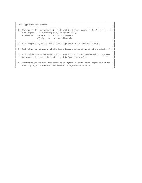
ÚÄÄÄÄÄÄÄÄÄÄÄÄÄÄÄÄÄÄÄÄÄÄÄÄÄÄÄÄÄÄÄÄÄÄÄÄÄÄÄÄÄÄÄÄÄÄÄÄÄÄ ÄÄÄÄÄÄÄÄÄÄÄÄÄÄÄÄÄÄÄÄ¿³ CCB Application Notes: ³³ ³³ 1. Character(s) preceded & followed by these symbols (À Ù) or (Ú ¿) ³³ are super- or subscripted, respectively. ³³ EXAMPLES: 42mÀ3Ù = 42 cubic meters ³³ COÚ2¿ = carbon dioxide ³³ ³³ 2. All degree symbols have been replaced with the word deg. ³³ ³³ 3. All plus or minus symbols have been replaced with the symbol +/-. ³³ ³³ 4. All table note letters and numbers have been enclosed in square ³³ brackets in both the table and below the table. ³³ ³³ 5. Whenever possible, mathematical symbols have been replaced with ³³ their proper name and enclosed in square brackets. ³ÀÄÄÄÄÄÄÄÄÄÄÄÄÄÄÄÄÄÄÄÄÄÄÄÄÄÄÄÄÄÄÄÄÄÄÄÄÄÄÄÄÄÄÄÄÄÄÄÄÄÄ ÄÄÄÄÄÄÄÄÄÄÄÄÄÄÄÄÄÄÄÄÙ
<strong>MIL</strong>-<strong>HDBK</strong>-<strong>1004</strong>/630 MAY 1988SUPERSEDINGDM 4.61 DECEMBER 1979<strong>MIL</strong>ITARY HANDBOOKLIGHTNING PROTECTIONAMSC N/ADISTRIBUTION STATEMENT A. APPROVED FOR PUBLIC RELEASE: DISTRIBUTION ISUNLIMITED.AREA FACR
ABSTRACTThis handbook provides basic design guidance developed from extensivere-evaluation of facilities. It is intended for use by experienced architectsand engineers. The contents cover electrical design considerations applyingto lightning protection systems.
PAGE iv IS INTENTIONALLY BLANK
FOREWORDThis handbook has been developed from an evaluation of facilities in the shoreestablishment, from surveys of the availability of new materials andconstruction methods, and from selection of the best design practices of theNaval Facilities Engineering Command (<strong>NAVFAC</strong>ENGCOM), other Governmentagencies, and the private sector. This handbook was prepared using, to themaximum extent feasible, national professional society, association, andinstitute standards. Deviations from this criteria, in the planning,engineering, design, and construction of Naval shore facilities, cannot bemade without prior approval of <strong>NAVFAC</strong>ENGCOMHQ Code 04.Design cannot remain static any more than can the functions it serves or thetechnologies it uses. Accordingly, recommendations for improvement areencouraged and should be furnished to Commanding Officer, Chesapeake Division,Naval Facilities Engineering Command, Code 406, Washington Navy Yard, Building212, Washington, D.C. 20374-2121; telephone (202) 433-3314THIS HANDBOOK SHALL NOT BE USED AS A REFERENCE DOCUMENT FOR PROCUREMENT OFFACILITIES CONSTRUCTION. IT IS TO BE USED IN THE PURCHASE OF FACILITIESENGINEERING STUDIES AND DESIGN (FINAL PLANS, SPECIFICATIONS, AND COSTESTIMATES). DO NOT REFERENCE IT IN <strong>MIL</strong>ITARY OR FEDERAL SPECIFICATIONS OROTHER PROCUREMENT DOCUMENTS.
ELECTRICAL ENGINEERING CRITERIA MANUALSCriteriaManual Title PAÄÄÄÄÄÄÄÄÄÄÄÄÄÄÄÄÄÄÄÄÄÄÄÄÄÄÄÄÄÄÄÄÄÄÄÄÄÄÄÄÄÄÄÄÄÄÄÄÄÄÄ ÄÄÄÄÄÄÄÄÄÄÄÄÄÄÄÄÄÄÄÄ<strong>MIL</strong>-<strong>HDBK</strong>-<strong>1004</strong>/1 Preliminary Design Considerations CHESDIV<strong>MIL</strong>-<strong>HDBK</strong>-<strong>1004</strong>/2 Power Distribution Systems PACDIV<strong>MIL</strong>-<strong>HDBK</strong>-<strong>1004</strong>/3 Switchgear and Relaying CHESDIV<strong>MIL</strong>-<strong>HDBK</strong>-<strong>1004</strong>/4 Electrical Utilization Systems CHESDIVDM-4.05 400-Hz Generation and Distribution CHESDIVSystems<strong>MIL</strong>-<strong>HDBK</strong>-<strong>1004</strong>/6 <strong>Lightning</strong> <strong>Protection</strong> CHESDIVDM-4.07 Wire Communication and Signal CHESDIVSystemsDM-4.09 Energy Monitoring and Control HDQTRSSystems<strong>MIL</strong>-<strong>HDBK</strong>-<strong>1004</strong>/10 Cathodic <strong>Protection</strong> (Proposed) NCELNOTE: Design manuals, when revised, will be converted to military handbooks.This handbook is issued to provide immediate guidance to the user.However, it may or may not conform to format requirements of<strong>MIL</strong>-<strong>HDBK</strong>-1006/3 and will be corrected on the next update.
LIGHTNING PROTECTIONCONTENTSPageSection 1CODES AND POLICIES1.1 Scope . . . . . . . . . . . . . . . . . . . . . . . .11.2 Cancellation . . . . . . . . . . . . . . . . . . . .11.3 Policies . . . . . . . . . . . . . . . . . . . . . .11.3. <strong>Lightning</strong> <strong>Protection</strong> . . . . . . . . . . . . . . . .11.3.2 Local Codes . . . . . . . . . . . . . . . . . . . . .11.3.3 National Codes . . . . . . . . . . . . . . . . . . .1Section 2SYSTEMS2.1 Types . . . . . . . . . . . . . . . . . . . . . . . .22.1.1 Primary . . . . . . . . . . . . . . . . . . . . . . .22.1.2 Secondary . . . . . . . . . . . . . . . . . . . . . .22.1.3 Combination . . . . . . . . . . . . . . . . . . . . .22.2 Primary Systems . . . . . . . . . . . . . . . . . . .22.2.1 <strong>Lightning</strong> Masts . . . . . . . . . . . . . . . . . . .22.2.2 Grounded Aerial Conductors . . . . . . . . . . . . .22.3 Secondary Systems . . . . . . . . . . . . . . . . . .22.3.1 Air Terminals . . . . . . . . . . . . . . . . . . . .2Section 3SYSTEM COMPONENTS3.1 Masts . . . . . . . . . . . . . . . . . . . . . . . .103.1.1 Material . . . . . . . . . . . . . . . . . . . . . .103.1.2 Top Point . . . . . . . . . . . . . . . . . . . . . .103.1.3 Height and Location . . . . . . . . . . . . . . . . .103.1.4 Zone of <strong>Protection</strong> . . . . . . . . . . . . . . . . .103.1.5 Joint Design . . . . . . . . . . . . . . . . . . . .103.1.6 Joint Test . . . . . . . . . . . . . . . . . . . . .113.1.7 Metal Mast Foundation . . . . . . . . . . . . . . . .113.2 Grounded Aerial Conductors . . . . . . . . . . . . .113.3 Earthed Energy Dissipation Systems . . . . . . . . .113.3.1 Electrodes . . . . . . . . . . . . . . . . . . . . .113.3.2 Ground Counterpoise . . . . . . . . . . . . . . . . .113.3.3 Radials . . . . . . . . . . . . . . . . . . . . . . .113.3.4 Plates . . . . . . . . . . . . . . . . . . . . . . .12Section 4INSTALLATION4.1 General . . . . . . . . . . . . . . . . . . . . . . .134.2 Design Calculations . . . . . . . . . . . . . . . . .134.2.1 Earth Resistance . . . . . . . . . . . . . . . . . .134.2.2 Soil Resistivity . . . . . . . . . . . . . . . . . .134.3 <strong>NAVFAC</strong> Design Guides . . . . . . . . . . . . . . . .134.4 Ordnance Facilities . . . . . . . . . . . . . . . . .134.4.1 Storage and Handling Facilities Above Ground . . . .134.4.2 Earth-Covered Magazines . . . . . . . . . . . . . . .134.4.3 Cranes on Piers and Wharves . . . . . . . . . . . . .134.4.4 Marshalling Yards (Truck and Railroad) . . . . . . .144.4.5 Railroad Sidings . . . . . . . . . . . . . . . . . .144.4.6 Electric Service . . . . . . . . . . . . . . . . . .14
Page4.4.7 Exterior Overhead Pipelines . . . . . . . . . . . . .144.4.8 Fences . . . . . . . . . . . . . . . . . . . . . . .144.5 Generating Plants . . . . . . . . . . . . . . . . . .144.5.1 Surge <strong>Protection</strong> . . . . . . . . . . . . . . . . . .144.5.2 Grounding . . . . . . . . . . . . . . . . . . . . . .154.6 Outdoor Substations or Switching Stations . . . . . .154.6.1 Air Terminals . . . . . . . . . . . . . . . . . . . .154.6.2 Grounded Aerial Conductors . . . . . . . . . . . . .154.6.3 Grounding . . . . . . . . . . . . . . . . . . . . . .154.7 Transmission and Distribution Lines . . . . . . . . .154.7.1 Distribution Line Clearances . . . . . . . . . . . .154.7.2 Transmission Line Clearances . . . . . . . . . . . .154.7.3 Clearance Calculation . . . . . . . . . . . . . . . .164.8 Flagpoles and Chimneys . . . . . . . . . . . . . . .164.9 Towers and Antennas . . . . . . . . . . . . . . . . .164.10 Aircraft and Aircraft Hangars . . . . . . . . . . . .164.11 Ordinary Buildings . . . . . . . . . . . . . . . . .164.12 Obstruction Lights . . . . . . . . . . . . . . . . .16APPENDICESAPPENDIX AAPPENDIX BPrimary <strong>Lightning</strong> <strong>Protection</strong> for Ordnance HandlingFacilities . . . . . . . . . . . . . . . . . . . .17International System of Units (SI) ConversionFactors . . . . . . . . . . . . . . . . . . . . . .37FIGURES1 Primary <strong>Lightning</strong> <strong>Protection</strong> System . . . . . . . . . . . . . .32 <strong>Lightning</strong> Mast Ground Connection Details . . . . . . . . . . .43 Secondary <strong>Lightning</strong> <strong>Protection</strong> or Grounding System . . . . . .54 Bonding and Grounding of Railroad Track . . . . . . . . . . . .65 Concrete and Steel Ground Connections for Secondary System. . .76 Other Grounding Details for Secondary System . . . . . . . . .87 Other Grounding Details . . . . . . . . . . . . . . . . . . . .9BIBLIOGRAPHY . . . . . . . . . . . . . . . . . . . . . . . . . . .40REFERENCES . . . . . . . . . . . . . . . . . . . . . . . . . . .41
PAGE ix IS INTENTIONALLY BLANK
Section 1: CODES AND POLICIES1.1 Scope. This handbook presents data and considerations that arenecessary for the proper design of lightning protection systems.1.2 Cancellation. This handbook cancels and supersedes <strong>NAVFAC</strong> DM-4.6,Electrical Engineering, <strong>Lightning</strong> and Cathodic <strong>Protection</strong> of December 1979.Cathodic protection in DM-4.6 is to be covered in the proposed militaryhandbook, <strong>MIL</strong>-<strong>HDBK</strong>-<strong>1004</strong>/10.1.3 Policies. The policy of the Naval Facilities Engineering Command isto provide the most effective degree of lightning protection.1.3.1 <strong>Lightning</strong> <strong>Protection</strong>. As a minimum, for all ordinary, non-ordnancefacilities requiring lightning protection, the requirements of National Fire<strong>Protection</strong> Association (NFPA) NFPA 78, <strong>Lightning</strong> <strong>Protection</strong> Code, should befollowed. The requirements of this handbook must be followed for ordnancefacilities and those facilities within the scope of NFPA 78. Ordnancefacilities, such as magazines and other structures, truck and railroadmarshalling yards, railroad sidings, and wharves and piers where ordnance andexplosives are handled and stored, shall be provided with special protectivemeasures. Design for these systems shall be in accord with criteria in thishandbook; DOD-STD-6055.9, Ammunition and Explosives Safety Standards; <strong>MIL</strong>-<strong>HDBK</strong>-419, Grounding, Bonding and Shielding; and NAVSEA OP-5, Vol. 1,Ammunition and Explosives Ashore.1.3.2 Local Codes. Although the federal Government is not required toconform to local (city or district) building and electrical codes forinstallations within Government ownership lines, consideration should be givento local standards and regulations wherever practicable.1.3.3 National Codes. The NFPA and the National Electrical ManufacturersAssociation (NEMA) have established basic minimum standards of design andinstallation practice including: NFPA 70, National Electrical Code (NEC);NFPA 70B, Electrical Equipment Maintenance; NFPA 78; and American NationalStandards Institute (ANSI) ANSI C2, National Electrical Safety Code. Thesestandards shall be complied with in all projects. Approval of theUnderwriters Laboratories Inc. should be considered for all electricalmaterials, fittings, and appliances where possible. Refer to Underwriters'Laboratory (UL) UL 96, <strong>Lightning</strong> <strong>Protection</strong> Components, UL 96A, InstallationRequirements for <strong>Lightning</strong> <strong>Protection</strong> Systems, and UL 467, Grounding andBonding Equipment.1
Section 2: SYSTEMS2.1 Types. <strong>Lightning</strong> protection systems are either primary, secondary,or a combination of primary and secondary.2.1.1 Primary. Design primary protection to prevent damage from directlightning strokes by diverting any charges from structures through a lowresistance path to earth.2.1.2 Secondary. Design secondary protection to prevent metal parts ofbuildings, building contents, or other types of structures from accumulatingelectric charges that can cause sparking or flashover. Sparking or flashoveris likely to occur when metal objects are proximate. In the event of alightning discharge, the potential of independently grounded metal objects canchange with respect to nearby objects generating flashover between theobjects.2.1.3 Combination. The installation of a primary and a secondaryprotection system for the same structure is not always required. A secondarystatic ground system providing an interconnection of metallic masses within abuilding or on piers and wharves may also be required with a primary lightningprotection system. When a structure is equipped with both primary andsecondary systems, interconnect all grounds.2.2 Primary Systems. Design protection based on 100 ft (30.5 m)lightning strike arc. Design either primary or secondary type and determinemast locations or grounded aerial conductors and their heights. Mastlocations or grounded aerial conductors and their heights influence the typeof masts along with mast foundation requirements and the location of theground counterpoise. Primary protection shall consist of lightning masts orgrounded aerial conductors as described in paras. 2.2.1 and 2.2.2.2.2.1 <strong>Lightning</strong> Masts. <strong>Lightning</strong> masts (freestanding air terminals)placed around a facility and connected to a buried ground counterpoise (seeFigures 1 and 2).2.2.2 Grounded Aerial Conductors. Overhead conductors spanned above afacility and connected to a buried ground counterpoise.2.3 Secondary Systems. A secondary system generally consists of aburied ground counterpoise to which all metal parts, including reinforcingsteel of the building or other structure, are connected (see Figures 3, 4, 5,6, and 7). An equipment ground bus may be utilized for the grounding of thebuilding contents. The ground bus shall not form a loop. Connect ground busto ground counterpoise as shown in Figure 3.2.3.1 Air Terminals. Points (lightning rods) mounted on the salient partsof facilities and connected to the ground counterpoise may be used forprotection for certain specific applications in a secondary system.
Section 3: SYSTEM COMPONENTS3.1 Masts. <strong>Lightning</strong> masts shall be tapered metal, self-supportingtype, (single section design or multisection design) with slip joints, asdictated by total height of mast. The cross section shall be circular orpolygonal, symmetrical about the longitudinal axis, and uniform inconfiguration throughout the entire length. Wood masts may be used only whenheights and structural strength permit and shall be electrical pole lineembedded type, topped with a lightning rod or metal cap and with two barecopper ground wires not less than No. 1/0 AWG (53.5 mmÀ2Ù), run down each sideof the pole to the ground system. The ground wires shall have a protectivemolding extending from grade level to a point at least 10 ft (3.05 m) abovegrade.3.1.1 Material. Metal material shall be corrosion-resistant steel,noncorrosion-resistant steel with hot-dipped galvanized finish, or aluminumfor single section or multiple section masts with anchor bolt mounting. Nocombination of materials shall be used that form an electrolytic couple which,in the presence of moisture, causes accelerated corrosion.3.1.2 Top Point. Mast top shall be fitted with a copper or bronze airterminal or metal cap to take the lightning stroke. The point shall beincluded in the determined overall height of the mast.3.1.3 Height and Location. Refer to Appendix A for determination of mastheight and for location as related to structure being protected. Masts ofheights up to 40 ft (12.2 m) shall be of single section design. Masts 40 to70 ft (12.2 to 21.34 m) in height should be single-section design if deliveryto the site is practical. Design for masts in excess of 150 ft (45 m) receivespecial consideration.3.1.4 Zone of <strong>Protection</strong>. A lightning mast system establishes azone-of- protection. The-zone-of-protection is described by an arc having aradius not greater than 100 ft (30.5 m). To prevent sideflashes, each mastshall be separated from the structure by not less than one-half of the heightof the assumed salient plane, but never less than 6 ft (2 m). The maximumdistance from the structure shall be 25 ft (7.6 m).3.1.5 Joint Design. Slip-joint design shall meet the followingrequirements:a) Assure overall structural integrity of the mast.b) Include field assembly requirement to assure a snug fit, so thatjoints of the mast will not loosen when subjected to vibrational modes causedby wind or other means after erection.c) Be compatible with field erection requirements to assure ease ofinstallation at the site.d) Have good metal-to-metal contact, so that electricalconductivity will be equal to or better than the parent metal used.
3.1.6 Joint Test. After assembly, each joint shall be tested at the siteand shall be measured by a digital ohmmeter with a 0.01-ohm resolution and anaccuracy of 5 percent of the reading, plus one digit. Tests shall consist ofcomparative measurements across slip joints, with equal spacing of meterprobes at least 4 ft (1.22 m) apart. An acceptable joint is one yielding ameasurement equal to or less than a similar measurement of the parent metal ina given section of the mast, with the same spacing of the meter probes. Thelowest meter range providing an indication in the scale region of greatestaccuracy should be used. If the meter reads zero or infinity, an incorrectscale has been chosen or the meter is broken.3.1.7 Metal Mast Foundation. Foundations for setting metal masts shall bein accordance with the following:a) Steel or aluminum, mounted by anchor bolts set in a concretefoundation poured in place. Follow manufacturer's recommendations forfoundation design and type and for setting of anchor bolts.b) Steel, mounted by means of a stub set directly into a concretefoundation. Corrosion-resistant steel masts may be set directly into earthwhere soil conditions permit.3.2 Grounded Aerial Conductors. Overhead conductors shall be spannedbetween masts and connected to a ground counterpoise to suit the type ofinstallation. (Refer to Appendix A.)3.3 Earthed Energy Dissipation Systems3.3.1 Electrodes. Made electrodes, as defined in the NEC, shall consistof ground rods not less than 3/4 in. (19 mm) diameter and 10 ft (3.05 m)long. Ground rods shall be copper clad steel or solid copper. Connections toground rods shall be made by bolted clamp type devices.3.3.2 Ground Counterpoise. Each ground counterpoise shall consist of aNo. 1/0 AWG (53.5 mmÀ2Ù) bare copper cable completely surrounding thefacility, with its ends connected together to form a closed loop. The size ofany strand of the cable shall be not less than No. 17 AWG (1.04 mmÀ2Ù). Thecounterpoise shall be buried at least 30 in. (762 mm) below grade, external tothe structure and away from structural foundations or footings (see Figures 1and 3). Each counterpoise shall be fixed by driven ground rods. Connectionat each ground rod shall be made with a bolted clamp type device to facilitatedisconnection of the counterpoise from the ground rod for periodic testing.3.3.3 Radials. Radial systems shall consist of No. 1/0 AWG (53.5 mmÀ2Ù)bare copper cables arranged in a star pattern with the structure at thecenter. The size of any strand shall be not less than No. 17 AWG (1.04mmÀ2Ù). The radials shall be buried at least 30 in. (762 mm) below grade,external to the structure. Each radial shall be fixed by ground rods.Connection at each ground rod shall be made with a bolted device to facilitatedisconnection of the radials from the ground rods for periodic testing.Quantity and length of radials shall be as required to provide the requiredground resistance. Refer to IEEE 142, Recommended Practice for Grounding,Industrial and Commercial Power Systems, for resistance calculations.
3.3.4 Plates. The use of plate electrodes is discouraged due to the highcost of achieving proper grounding effects with this system.
Section 4: INSTALLATION4.1 General. <strong>Lightning</strong> protection systems shall be provided inaccordance with this manual.4.2 Design Calculations. Design calculations shall consider earthresistance and shall be based upon the soil resistivity for the specificlocation. Computer programs are available and should be used wheneverpossible. Project design criteria shall include names of approved computerprograms for use in design.4.2.1 Earth Resistance. Maximum ground resistance for any lightningprotection system should not exceed 10 ohms. In high resistance soils or rockformation, it may be necessary to provide ground counterpoises or artificialgrounds or to sink ground wells. After installation, each system shall betested by the single, direct reading instrument method. Where characteristicsare unknown, trial grounds should be installed and periodically tested duringthe course of at least 1 year to include seasonal variations. Refer topara. 4.5.2 for approved grounding methods.4.2.2 Soil Resistivity. Project criteria will set forth the specific soilresistivity values to be used for grounding system design.4.3 <strong>NAVFAC</strong> Design Guides. For specific criteria and sample layouts forsystems, refer to NAVSEA OP-5, Vol. I, and Appendix A of this handbook.4.4 Ordnance Facilities. Ordnance facilities shall be protected inaccordance with the following criteria: DOD-STD-6055.9; <strong>MIL</strong>-<strong>HDBK</strong>-419; NAVSEAOP-5, Vol. I; NFPA 78; and Appendix A of this handbook.4.4.1 Storage and Handling Facilities Above Ground. Provide a primaryprotection system consisting of lightning masts or overhead conductors spacedaround the facility. Connect the masts and all metalwork in the vicinity,such as railroad tracks, metal sheaths of underground cables, and metal pipingand conduits below ground that do not extend into the building or otherstructure being protected, to the primary ground counterpoise. All railroadtracks that extend into the building or structure shall also be grounded at aminimum of 10 ft (3.05 m) from the building or structure.4.4.2 Earth-Covered Magazines. Provide a secondary protection system.Where a metal ventilator provides a salient point above the structure, mount apointed lightning rod on the ventilator and connect it to the secondary groundcounterpoise. A pointed lightning rod should also be mounted on the concreteportal wall and connected to the secondary ground counterpoise. Bond togetherreinforcing steel by wrapping it with wire and connecting it to the secondaryground counterpoise.4.4.3 Cranes on Piers and Wharves. Provide a primary protection systemconsisting of overhead conductors spanned between structural supports andconnected to ground rods or to metal plates submersed in water.
4.4.4 Marshalling Yards (Truck and Railroad). Provide a primaryprotection system consisting of overhead conductors spanned between structuralsupports and connected to a primary ground counterpoise. Ground all metalparts and reinforcing steel of above grade structures to the groundcounterpoise. The reinforcing steel of precast concrete slabs should begrounded, but where inaccessible within the slabs, it is permissible to omitsuch grounding. Ground railroad tracks 10 ft (3.05 m) or more outside ofbarriers at entrances and exits to the yard and where they cross acounterpoise (see Figure 1).4.4.5 Railroad Sidings. Provide a primary protection system consisting ofoverhead conductors spanned between structural supports and connected toground rods. Ground all metal parts and reinforcing steel of abovegroundstructure to driven ground rods. Ground all railroad tracks to ground rodslocated 10 ft (3.05 m) or more outside of the entrance to barrier.4.4.6 Electric Service. Electric and communication services to explosivesoperating buildings and magazines shall be run underground in metallic conduitfor the last 50 ft (15 m). Services to buildings not containing explosivesmay be overhead. The line side of the main protective device shall beprovided with suitable surge arresters. Surge arresters shall be located atthe service transition to underground conduit outside the 50 ft (15 m) limit.A separate ground shall be provided at the secondary electric serviceentrance. This ground shall be bonded to the facility ground counterpoise.The electric supply to an explosives area shall be arranged so that it can becut off by switching devices located at one or more control points outside ofand immediately adjacent to the explosives areas.4.4.7 Exterior Overhead Pipelines. Bond overhead pipes which enter abuilding, storage facility, or area to all metal objects that are withinsideflash clearance of the pipes where they are in a zone of lightningprotection. Pipe segments shall be electrically continuous.4.4.8 Fences. Fences shall be grounded on each side of every gate, atpoints 150 ft (45 m) on each side of high-tension line crossings, and at 150ft (45 m) intervals along the fence where high-tension lines (as defined byANSI C2) are directly overhead and run parallel to the fence. Fences shallbe grounded every 1,000 ft to 1,500 ft (300 m to 450 m) of length when fencesare in isolated places and at lesser distances depending upon proximity offence to public roads, highways, and buildings. The ground shall be made witha bolted connection at a fence post by the use of No. 2/0 AWG (67.4 mmý)copper cable. Where plastic coated fabric is used, the post shall be bolted,and each strand of the fence shall be brazed to the metallic bare conductors.The conductors shall then be grounded.4.5 Generating Plants. Commercial type, metal-oxide, surge arrestersshall be provided on all overhead feeders adjacent to a plant as described inparas. 4.5.1 and 4.5.2.4.5.1 Surge <strong>Protection</strong>. Surge protection shall be provided between theaerial surge arresters and generator or on a bus for several generators.Where a generator is connected to an overhead line through a transformer,provide a station type surge arrester on the high voltage side of thetransformer.
4.5.2 Grounding. Provide protection for smokestacks as described inpara. 4.8, and ground all steel columns, beams, trusses, and equipment framesat their lowest points to a low resistance station grounding system.4.6 Outdoor Substations or Switching Stations. All overhead feedersshall be provided with surge arresters at the station which shall be connectedto their own ground rod system. The ground rod system shall be connectedbelow grade to the station ground mat. Refer to IEEE 80, Guide for Safety inSubstation Grounding, and IEEE 81, Guide for Measuring Earth Resistivity,Ground Impedance, and Earth Surface Potentials of a Ground System. Additionalprotection shall be as described in paras. 4.6.1 through 4.6.3.4.6.1 Air Terminals. On distribution metal station structures, providelightning rods at each corner of the station, extending rods above thestructure and the electric conductors. Connect the structure and allequipment frames, transformers, tanks, and bases to a low resistance groundingsystem.4.6.2 Grounded Aerial Conductors. In areas where lightning storms areprevalent, install overhead ground conductors above the transmission anddistribution system conductors to form a ground wire network over distributionstations. Extend the overhead ground wires out over transmission lines for aminimum of 1/2 mile (0.8 km). Aerial ground wires shall be grounded at thestation and at each pole.4.6.3 Grounding. Provide a ground system of No. 2/0 AWG (67.4 mmý)copper cable, welded to the columns and equipment frames and connected to aground system. Provide a ground mat for stations supplying distributionvoltages and a counterpoise for substations supplying utilization voltages.A ground mat shall consist of a system of bare conductors located on or belowgrade throughout the station and connected to a counterpoise to provideprotection from dangerous touch voltages.4.7 Transmission and Distribution Lines. Overhead aerial lines shall beprovided with lightning protection coordinated with NFGS-16302 and inaccordance with standard utility practice at the project location. Acceptableshielding results when a perpendicular line from grade to the ground wire andwhen a line from the ground wire to the conductor protected do not result inan angle greater than 30ø. Overhead ground wires may be steel, copper,aluminum, or copper clad steel, with sizes dependent upon mechanicalrequirements but not smaller than No. 1/0 AWG (53.5 mmý) copper-equivalent.Ground the overhead ground wires at each pole. Where an overhead electrictransmission and distribution line transitions to underground, the undergroundcable shall be provided with lightning protection.4.7.1 Distribution Line Clearances. The towers or poles supportingdistribution lines operating at less than 69 kV, and unmanned electricsubstations operating at less than 69 kV, shall not be closer to ordnancefacilities than public traffic route distances as defined in DOD-STD-6055.9.4.7.2 Transmission Line Clearances. For transmission lines operating at69 kV and above, and for electric substations operating at 69 kV and abovewhich are part of a system serving a substantial off base area, both thetowers or poles supporting the lines and the stations shall not be closer to15
ordnance facilities than inhabited building distances, as defined inDOD-STD-6055.9. When failure of the lines and stations will not cause serioushardships, both the towers or poles supporting the lines and the stations maybe located at public traffic route distances.4.7.3 Clearance Calculation. Line clearance distance calculations shallbe based on airblast over pressure only. Fragment distances will not be used.4.8 Flagpoles and Chimneys. Provide grounding at the bases of metalchimneys or flagpoles at the lowest points in accordance with NFPA 78.Provide protection for other chimneys and flagpoles in accordance with NFPA78.4.9 Towers and Antennas. Provide grounding at the bases of metallictowers or at the lowest points in accordance with NFPA 78. At least twocolumns should be connected to an adequate ground by No. 2/0 AWG (67.4 mmý)copper cable. Provide the same grounding for metallic watch/surveillancetower structures. Structures adjacent to metallic towers and within theirzone of protection do not require primary protection, but all metal frames,ventilators, doors, and window frames shall be bonded together and adequatelygrounded. Provide antenna lead-ins with spark gap protection connected toground adjacent to supporting structure of antennas.4.10 Aircraft and Aircraft Hangars. Provide aircraft and aircrafthangars in accordance with NFPA 78. Grounding receptacles shall be located inaccordance with DM-21.1, Airfield Geometric Design, and DM-21.9, SkidResistant Runway Surface.4.11 Ordinary Buildings. Provide protection in accordance with NFPA 78.Health care facilities are included under ordinary buildings, exceptprotection for flammable liquids and gases shall apply as appropriate. Whereair terminals are located on flat roofs, either near mechanical equipment orin areas traversed by maintenance personnel, special consideration must begiven to preventing injury from tripping over air terminal points, such asinstalling longer or elevated air terminals.4.12 Obstruction Lights. Provide air terminals 1 ft (0.3048 m) above thetop of the obstruction lights. Provide surge arrestors connected to thelighting circuit conductors and bonded to the lightning protection system.
APPENDIX APRIMARY LIGHTNING PROTECTION FORORDNANCE HANDLING FACILITIES1. Scope. The following design method will provide adequate primarylightning protection for ordnance handling buildings with vertical masts, oroverhead aerial wiring, in the vicinity of the building to be protected. Thismethod can also be used to provide protection for a group of closelyassociated structures or complexes.2. General. Experiments have indicated that under certain assumed testconditions, a vertical conductor will generally divert to itself directlightning strikes which might otherwise fall within a cone shape or wedgeshape space zone-of-protection space in which the apex is the top of thevertical mast, or the overhead horizontal ground wiring of the wedge. In thiscase, the base is approximately two times the height of the mast or theoverhead horizontal ground cable.2.1 <strong>Lightning</strong> <strong>Protection</strong> System. The lightning protection systememployed herein is based on the zone-of-protection as determined by clearancearcs and a 100 ft (30.5 m) lightning striking distance. All masts andoverhead ground wiring that is used for the protection of a structure must beadequately grounded. If the structure being protected is of metal, groundingmust also be bonded to the structure. The ground resistance should not beover 10 ohms. A sufficient number of masts or overhead ground wires must beused so that the entire structure is covered by their zone-of-protection.3. Application of Criteria. The following criteria apply to primarylightning protection:a) Basic requirements are an adequate design for lightningprotection and economical cost of the system provided.b) All three dimensions, the length, the width, and the height, ofa structure to be protected by a primary lightning protection system are ofmajor importance in determining the height, number, and location of the mastsor the overhead aerial wiring which will be used to protect the structure.c) The spacing of the masts along the length of the structure shallbe a minimum of 1-1/2 times the height of the masts and a maximum of 200 ft(61 m).d) The distance "C" of the masts from the structure shall be onehalfthe height of the assumed salient plane (S/2) but never less than 6 ft(1.8 m) or more than 25 ft (7.6 m). In cases where a minor readjustment maybe necessary to accommodate road clearance, an exception shall not grosslyexceed the limits.
e) The height of the masts is determined by the Equation:where "M" is the height of the masts, "S" is the height of the assumed salientplane, "D" is the mast spacing on the diagonal axis as determined byEquation (1), with C = 40 ft (12 m). "P" is given an empirical value (seeAppendix A, A-1) according to the value of "D" as calculated from Equation(1).The height of the masts as determined by the formulae is based on thecondition that the structure to be protected is located between two parallelrows of masts. To determine the height of the masts, use Equation (1), andusing C = 40 ft (12 m), calculate for D, and then determine M by using thecurves of Appendix A, A-2, Chart No. 1.f) The protection of a structure by self-standing vertical mastsdictates that the distance from the center line of the structure or complex tothe masts on the normal or the diagonal axis must not be more than 100 ft(30.5 m). When this condition cannot be met, the protection of the structureor complex will be by overhead ground wiring. To determine the finaldistance, D1, along the diagonal axis, use Equation (1) substituting D1 for D,with C values between 6 ft (1.8 m) minimum to 25 ft (7.6 m) maximum. D1 shallnot exceed 100 ft (30.5 m).g) When overhead ground wiring are used for protection, support theoverhead ground wiring on masts located at the vicinity of the protectedstructure at distances from the structure established as 6 ft (1.8 m) minimumto 25 ft (7.6 m) maximum. The lowest point of mid-span sag in the overheadground wiring above the salient plane of the protected structure is to be noless than 10 ft (3.05 m). Increase the distance of cable which is runparallel to the structure by 1 ft (0.3 m) for each 10 ft (3.05 m) ofhorizontal cable greater than 50 ft (15 m). Determine mid-span sag of theoverhead ground wire from the curves of Appendix A, A-2.4. Graphic Examples. In Appendix A, A-3, Example 1: L, W, and S areknown, C is given the value of 40, B = 18 ft (explained in Appendix A, A-1,Definitions of Terms), and N is equal to 6. In Equation (1) substitute thesevalues and D is found to equal 98.5 ft. In Appendix A, A-1, refer to thecurves at point 98.5 ft (30 m) on the horizontal scale, then extend verticallyto the 50 ft slant line, and carry horizontally to the vertical scale, againusing Equation (1) and substituting actual distance C = 6 ft (1.8 m) minimumto 25 ft (7.6 m) maximum, this will show a mast height of 95.5 (29 m).
In accordance with para. 3, Appendix A, determine actual D1 distance from thecenter-line of the building or complex to row of masts on the diagonal axis.With C = 25 ft, D is equal to 82 ft.After the height and location of the masts have been determined,proceed as follows:a) Draw a plan of the building to scale. Locate the masts atdistances which are determined by the method shown in Appendix A, A-3,Example 1, Figure 1.b) Draw an elevation of the building to scale. Locate the masts atdistances which are determined by the method shown in Appendix A, A-3. Draw a100 ft striking distance radius from the apex of the masts to the center-lineof the building or complex as shown. Draw two arcs (the normal axis and thediagonal axis clearance arcs) as shown in Appendix A, A-4, from the point ofintersection with the center-line of the building. These arcs must clear thesalient plane.c) Draw a lengthwise scale elevation of the building. Locate themasts as shown in Appendix A, A-5 (refer to para. 4b, Appendix A). No part ofthe protected building should lie outside the zone-of-protection. Appendix A,A-6 through A-11 provide examples which illustrate application of thisprinciple.5. Facilities Other Than Structures. The following criteria apply forfacilities other than structures.a) This type of facility can be protected by using overhead groundcable spanned between two metal towers or poles which are effectively groundedand meet criteria in para. 3, Appendix A.b) In this system, the overhead cable will intercept lightningstrikes and the resulted electrical current will be safely carried to groundvia the cable and supporting towers or poles.c) The design method establishes the height of the horizontalground cable at mid-span to provide the required zone-of-protection for aspecific facility.d) The mid-span sag of the overhead cable must be included when theheight of the supporting towers or poles is determined (see Appendix A, A-2).e) Selection of cables is based on mechanical strength rather thanelectrical considerations. The overhead ground cable should be stranded,non-corrosive, copper coated steel wire. Minimum size shall be 3/8 in.(9.5 mm) high strength (7 No. 8 strands).f) The construction of the towers and their structural members orthe class of poles should be based on considerations of mechanical and windloading stresses.
g) Appendix A, A-12 and A-13 illustrate primary lightningprotection by overhead ground cables for railroad and truck marshalling yards,railroad siding and detail of overhead ground wire supporting poles andcounterpoise. Piers and wharves should be protected by meeting requirementsstated in paras. 1 and 3, Appendix A.h) To check the adequacy of the zone-of-protection when the heightof supporting towers or poles is determined, draw sketches to scale as shownin Appendix A, A-12 and A-13. The effective height of the overhead groundcable shall be maintained between the low point of the sag and the protectedfacility.
APPENDIX BINTERNATIONAL SYSTEM OF UNITS (SI) CONVERSION FACTORSU.S. INTERNATIONAL APPROXIMATEQUANTITY CUSTOMARY UNIT (SI) UNIT CONVERSIONLENGTHfoot(ft) meter(m) 1 ft = 0.3048 mfoot(ft) millimeter(mm) 1 ft = 304.8 mminch(in) millimeter(mm) 1 in = 25.4 mmAREA square yard(ydÀ2Ù) square meter(mÀ2Ù) 1 ydÀ2Ù = 0.836 127 mÀ2Ùsquare foot(ftÀ2Ù) square meter(mÀ2Ù) 1 ftÀ2Ù = 0.092 903 mÀ2Ùsquare inch(inÀ2Ù) square millimeter(mmÀ2Ù) 1 inÀ2Ù = 645.16 mmÀ2ÙVOLUME cubic yard(ydÀ3Ù) cubic meter(mÀ3Ù) 1 ydÀ3Ù = 0.764 555 mÀ3Ùcubic foot(ftÀ3Ù) cubic meter(mÀ3Ù) 1 ftÀ3Ù = 0.028 317 mÀ3Ùcubic inch(inÀ3Ù) cubic millimeter(mmÀ3Ù) 1 inÀ3Ù = 16,387.1 mmÀ3ÙCAPACITY gallon(gal) liter(L) 1 gal = 3.785 41 Lfluid ounce(fl oz) milliliter(mL)1 fl oz = 29.5735 mLVELOCITY, foot per second meter per second(m/s) 1 ft/s = 0.3048 m/sSPEED (ft/s or f.p.s.)mile per hour kilometer per hour 1 mile/h= 1.609 344 km/h(mile/h or m.p.h.) (km/h)ACCELERA-foot per second meter per second 1 ft/sÀ2Ù = 0.3048 m/sÀ2ÙTION squared(ft/sÀ2Ù) squared(m/sÀ2Ù)MASS short ton(2000lb) metric ton(t) 1 ton = 0.907 185 t(1000 kg)pound(lb) kilogram(kg) 1 lb = 0.453 592 kgounce(oz) gram(g) 1 oz = 28.3495 gDENSITY ton per cubic metric ton per cubic 1 ton/ydÀ3Ù =1.186 55t/mÀ3Ùyard(ton/ydÀ3Ù) meter(t/mÀ3Ù)pound per cubic kilogram per cubic 1 lb/ftÀ3Ù =16.0185 kg/mÀ3Ùfoot(lb/ftÀ3Ù) meter(kg/mÀ3Ù)FORCE ton-force(tonf) kilonewton(kN) 1 tonf = 8.896 44 kNkip(1000 lbf) kilonewton(kN) 1 kip = 4.448 22 kNpound-force(lbf) newton(N) 1 lbf = 4.448 22 NMOMENT ton-force foot kilonewton 1 tonf.ft = 2.711 64 kN.mOF FORCE (tonf.ft)meter(kN.m)TORQUE pound-force newton meter(N.m) 1 lbf.in = 0.112 985 N.minch(lbf.in)
APPENDIX BINTERNATIONAL SYSTEM OF UNITS (Continued)U.S. INTERNATIONAL APPROXIMATEQUANTITY CUSTOMARY UNIT (SI) UNIT CONVERSIONPRESSURE, ton-force per megapascal(MPa) 1 tonf/inÀ2Ù = 13.7895 MPaSTRESS square inch(tonf/inÀ2Ù)ton-force per kilopascal(kPa) 1 tonf/ftÀ2Ù = 95.7605 kPasquare foot(tonf/ftÀ2Ù)pound-force per kilopascal(kPa) 1 lbf/inÀ2Ù = 6.894 76 kPasquare inch(lbf/inÀ2Ù)pound-force per pascal(Pa) 1 lbf/ftÀ2Ù = 47.8803 Pasquare foot(lbf/ftÀ2Ù)WORK, kilowatthour(kWh) megajoule(MJ) 1 kWh = 3.6 MJENERGY British thermal kilojoule(kJ) 1 Btu = 1.055 06 kJQUANTITY unit(Btu)OF HEAT foot-pound-force joule(J) 1 ft.lbf = 1.355 82 J(ft.lbf)POWER, horsepower(hp) kilowatt(kW) 1 hp = 0.745 700 kWHEAT British thermal watt(W) 1 Btu/h = 0.293 071 WFLOW unit per hourRATE (Btu/h)foot pound-force watt(W) 1 ft.lbf/s = 1.355 82 Wper second(ft.lbf/s)COEF Btu per square watt per square 1 Btu/ = 5.678 26 W/FICIENT foot hour meter kelvin ftÀ2Ù.h. degF mÀ2Ù.KOF HEAT degreeTRANSFER Fahrenheit(Btu/ (W/mÀ2Ù.K)(U-value) ftÀ2Ù.hr. degF)THERMAL Btu per foot watt per meter 1 Btu/ = 1.730 73 W/CONDUC- hour kelvin (W/m.K) ft.h. degF m.KTIVITY Degree Fahrenheit(K-value) (Btu/ft.hr. degF)
APPENDIX B (Continued)AMERICAN WIRE GAGE (AWG) CONVERSIONAWG kCM mmÀ2Ù20 . . . . . . . . . . . . . 1.02 . . . . . . . . . . . . . . 0.51718 . . . . . . . . . . . . . 1.62 . . . . . . . . . . . . . . 0.82316 . . . . . . . . . . . . . 2.58 . . . . . . . . . . . . . . 1.3114 . . . . . . . . . . . . . 4.11 . . . . . . . . . . . . . . 2.0812 . . . . . . . . . . . . . 6.53 . . . . . . . . . . . . . . 3.3110 . . . . . . . . . . . . . 10.4 . . . . . . . . . . . . . . 5.268 . . . . . . . . . . . . . 16.5 . . . . . . . . . . . . . . 8.376 . . . . . . . . . . . . . 26.2 . . . . . . . . . . . . . . 13.34 . . . . . . . . . . . . . 41.7 . . . . . . . . . . . . . . 21.22 . . . . . . . . . . . . . 66.4 . . . . . . . . . . . . . . 33.61 . . . . . . . . . . . . . 83.6 . . . . . . . . . . . . . . 42.41/0 . . . . . . . . . . . . . 105.6 . . . . . . . . . . . . . . 53.52/0 . . . . . . . . . . . . . 133.1 . . . . . . . . . . . . . . 67.43/0 . . . . . . . . . . . . . 167.8 . . . . . . . . . . . . . . 85.04/0 . . . . . . . . . . . . . 211.6 . . . . . . . . . . . . . . 107.0
BIBLIOGRAPHYMilitary Handbooks Government agencies may obtain copies of militaryhandbooks from the United States Naval Publications and Forms Center, 5801Tabor Avenue, Philadelphia, PA 19120, TWX: 710-670-1685, TELEX: 834295,AUTOVON telephone 422-3321. Nongovernment organizations may obtain copies ofmilitary handbooks from the same source.<strong>MIL</strong>-<strong>HDBK</strong>-1008AFire <strong>Protection</strong> for Facilities Engineering,Design, and Construction
REFERENCESAmerican National Standard Institute (ANSI), 1430 Broadway, New York, NY10017.C2National Electric Safety CodeInstitute of Electrical and Electronics Engineers, Inc., IEEE Publications,345 East 47th Street, New York, NY 10017.80 Guide for Safety in Substation Grounding81 Guide for Measuring Earth Resistivity, GroundImpedance, and Earth Surface Potentials of aGround System142 Recommended Practice for Grounding Industrial andCommercial Power SystemsMilitary Standards and Handbooks, Government agencies may obtain copies ofmilitary standards and handbooks from the United States Naval Publications andForms Center, 5801 Tabor Avenue, Philadelphia, PA 19120, TWX: 710-670-1685,TELEX: 834295, AUTOVON telephone 422-3321. Nongovernment organizations mayobtain copies from the Superintendent of Documents, United States GovernmentPrinting Office, Washington, DC 20402.<strong>MIL</strong>-<strong>HDBK</strong>-419DOD-6055.9-STDGrounding, Bonding, and Shielding for ElectronicEquipments and Facilities.Ammunition and Explosives Safety StandardsNational Fire <strong>Protection</strong> Association (NFPA), Batterymarch Park, Quincy, MA02269.70 National Electrical Code70BElectrical Equipment Maintenance78 <strong>Lightning</strong> <strong>Protection</strong> Code
Naval Facilities Engineering Command (<strong>NAVFAC</strong>ENGCOM). Government agencies mayobtain copies of Design Manuals (DM), Naval Facilities Guide Specifications(NFGS) and Ordnance Pamphlets (OP), from the United States Naval Publicationsand Forms Center, 5801 Tabor Avenue, Philadelphia, PA 19120, TWX:710-670-1685, TELEX: 834295, AUTOVON telephone 422-3321. Nongovernmentorganizations may obtain copies from the Superintendent of Documents, UnitedStates Government Printing Office, Washington, DC 20402.DM-2 SeriesDM-4.2DM-7 SeriesDM-21.1DM-21.9NFGS-16302Structural EngineeringPower Distribution SystemsSoil Mechanics, Foundations and Earth StructuresAirfield Geometric DesignSkid Resistant Runway SurfaceOverhead Electrical WorkNAVSEASYSCOMNAVSEA OP-5Vol. IAmmunition and Explosives AshoreUL Standards, Underwriters Laboratories, Inc., 333 Pfingsten Road,Northbrook, IL 60062.UL 96UL 96AUL 467<strong>Lightning</strong> <strong>Protection</strong> ComponentsInstallation Requirements for <strong>Lightning</strong> <strong>Protection</strong>SystemsGrounding and Bonding EquipmentCUSTODIAN:NAVY - YDPREPARING ACTIVITYNAVY - YDPROJECT NO.FACR-0218