
You also want an ePaper? Increase the reach of your titles
YUMPU automatically turns print PDFs into web optimized ePapers that Google loves.
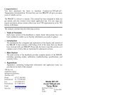
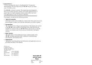
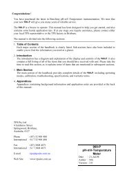
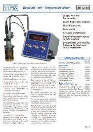
Congratulations !You have purchased the latest in benchtop <strong>pH</strong>-<strong>mV</strong>-<strong>Temp</strong>erature instrumentation.We trust that your new <strong>901</strong>-<strong>PH</strong> will give you many years of reliable service.The <strong>901</strong>-<strong>PH</strong> is a breeze to operate. This manual has been designed to help youget started, and also contains some handy application tips. If at any stage yourequire assistance, please contact either your local <strong>TPS</strong> representative or the <strong>TPS</strong>factory in Brisbane.The manual is divided into the following sections:1. Table of ContentsEach major section of the handbook is clearly listed. Sub-sections have alsobeen included to enable you to find the information you need at a glance.2. IntroductionThe introduction has a diagram and explanation of the display and controls ofthe <strong>901</strong>-<strong>PH</strong>. It also contains a full listing of all of the items that you shouldhave received with your <strong>901</strong>-<strong>PH</strong>. Please take the time to read this section, asit explains some of items that are mentioned in subsequent sections.3. Main SectionThe main section of the handbook provides complete details of the <strong>901</strong>-<strong>PH</strong>,including operating modes, calibration, troubleshooting, specifications, andwarranty terms.4. AppendicesAppendices containing background information and application notes areprovided at the back of this manual.<strong>TPS</strong> Pty Ltd4 Jamberoo StreetSpringwood, Brisbane,Australia, 4127Phone : (07) 32 900 400International : 61 7 32 900 400Fax : (07) 3808 4871International : 61 7 3808 4871EmailWeb Site: tps@tpssite.com.au: www.tpssite.com.au<strong>Model</strong> <strong>901</strong>-<strong>PH</strong><strong>pH</strong>-<strong>mV</strong>-<strong>Temp</strong>.<strong>Meter</strong>Handbook Version : 5Date: 30-Aug-99Author: MS
Page 21. Introduction1.1 <strong>901</strong>-<strong>PH</strong> Display and Controls1.2 <strong>901</strong>-<strong>PH</strong> Rear Panel Connectors
Page 41.4 Unpacking InformationBefore using your new <strong>901</strong>-<strong>PH</strong>, please check that the following accessories havebeen included:Part No1. <strong>901</strong>-<strong>PH</strong> <strong>pH</strong>-<strong>mV</strong>-<strong>Temp</strong>erature Instrument 1211022. Combination <strong>pH</strong> Sensor 1212073. <strong>Temp</strong>erature/ATC Sensor 1212454. <strong>pH</strong>6.88 Buffer, 200mL 1213065. <strong>pH</strong>4.00 Buffer, 200mL 1213816. AC/DC Power Adaptor 1300447. <strong>901</strong>-<strong>PH</strong> Handbook 130050Options that may have been ordered with your <strong>901</strong>-<strong>PH</strong>:1. Solution Guard Rod 1213602. Double Platinum Electrode for Karl Fischer 122207Titrations3. Flexible arm type sensor holder 1300884. RS232 option (includes cable) 1300295. RS232 Communication software for Windows 1300866. Recorder output option (includes cable) 1300287. Recorder PLUS RS232 option (includes cable) 130049
1.5 SpecificationsRanges Resolution Accuracy<strong>pH</strong> 0 to 14.00 <strong>pH</strong> 0.01 <strong>pH</strong> ±0.01 <strong>pH</strong><strong>mV</strong> 0 to ±600.0 <strong>mV</strong> 0.1 & 1 <strong>mV</strong> ±0.15 & ±1 <strong>mV</strong>0 to ±1500 <strong>mV</strong>(auto-ranging)<strong>Temp</strong>erature -10.0 to 120.0 O C 0.1 O C ±0.2 O CInput Impedance : >3 x 10 12 ΩAsymmetry Range : -1.00 to 1.00 <strong>pH</strong>Slope Range : 85.0 to 105.0%<strong>Temp</strong>erature Compensation : 0 to 100.0 o C, automatic or manualRecorder Output : <strong>pH</strong> : 0 to 14.00 <strong>pH</strong> for 0 to 2000 <strong>mV</strong>i.e. <strong>pH</strong>7.00 = 1000 <strong>mV</strong><strong>mV</strong> : -1500 to +1500 <strong>mV</strong> for 0 to 2000 <strong>mV</strong>i.e. 0 <strong>mV</strong> = 1000 <strong>mV</strong><strong>Temp</strong> : -10.0 to 120.0 O C for 0 to 2000 <strong>mV</strong>i.e. 0.0 O C = 152 <strong>mV</strong>Output impedance approx 1000 Ohms.Power: 12V DC by AC/DC power adaptor.Dimensions: 270 x 210 x 75 mmMass: Instrument only : Approx 1.0 kgFull Kit : Approx 2.5 kgEnvironment <strong>Temp</strong>erature : 0 to 45 o CHumidity : 0 to 90 % R.H.Page 5
Page 62. Operating ModesIf the <strong>901</strong>-<strong>PH</strong> IS NOT fitted with the RS232 option, press thethrough the three operating modes as follows…key to roll<strong>pH</strong> Mode 7.00<strong>pH</strong> 25.0 o c↓<strong>mV</strong> Mode 500.0<strong>mV</strong> 25.0 o c↓<strong>Temp</strong>erature Mode 25.0 o c↓Back to <strong>pH</strong> ModeIf the <strong>901</strong>-<strong>PH</strong> IS fitted with the RS232 option, press thethrough the five operating modes as follows…key to roll<strong>pH</strong> Mode 7.00<strong>pH</strong> 25.0 o c↓<strong>mV</strong> Mode 500.0<strong>mV</strong> 25.0 o c↓<strong>Temp</strong>erature Mode 25.0 o c↓RS232 Send Rate↓RS232 Baud Rate↓Back to <strong>pH</strong> ModeSend Rate ↑ 0↓Baud Rate ↑9600↓
3. <strong>pH</strong> Calibration3.1 Calibration Procedure1. Switch the <strong>901</strong>-<strong>PH</strong> on and select <strong>pH</strong> mode (section 2).Page 72. Plug the <strong>pH</strong> sensor into the Sensor socket and the temperature sensor intothe <strong>Temp</strong> socket.3. Ensure that temperature has already been calibrated or manually set (seesections 5.1 and 5.4). NOTE: A " ∗ " in place of the decimal point in thetemperature readout indicates that temperature is not calibrated.4. Ensure that the primary and secondary buffers to be used have beencorrectly selected for automatic buffer recognition. See section 8.5. Remove the wetting cap from the <strong>pH</strong> sensor.6. Rinse the <strong>pH</strong> and <strong>Temp</strong>erature sensors in distilled water and blot them dry.7. Place both sensors into a small sample of primary buffer (<strong>pH</strong>6.88 or <strong>pH</strong>7.00)so that the bulb and reference junction are both covered, as per the diagrambelow.DO NOT place the sensors directly into the buffer bottle.
Page 88. When the reading has stabilised, press the key to calibrate. If a 1point calibration has been performed, a " ∗ " in place of the decimal pointwill not be removed until a full 2 point calibration has been performed.9. Rinse the <strong>pH</strong> and <strong>Temp</strong>erature sensors in distilled water and blot them dry.10. Place both sensors into a small sample of secondary buffer (<strong>pH</strong>4.00, <strong>pH</strong>9.23or <strong>pH</strong>10.01) so that the bulb and reference junction are both covered, as perthe diagram in step 7 above.DO NOT place the sensor directly into the buffer bottle.NOTE: <strong>pH</strong>9.23 and <strong>pH</strong>10.01 buffers are highly unstable. Avoid usingthese buffers if possible. Discard immediately after use.When the reading has stabilised, press thekey to calibrate.The " ∗ " in the <strong>pH</strong> reading will now be replaced by a decimal point ifcalibration was successful.11. The <strong>901</strong>-<strong>PH</strong> is now calibrated and is ready for use.Discard the used samples of buffer.3.2 Calibration Notes1. A 1-point calibration should be performed at least weekly. In applicationswhere the sensor junction can become blocked (eg. wines, dairy products,mining slurries etc) a 1-point calibration may have to be done daily.2. A full 2-point calibration should be performed at least monthly. Of course,more frequent calibration will result in greater confidence in results.3. All calibration information is retained in memory when the <strong>901</strong>-<strong>PH</strong> isswitched off, even when the power supply is removed.
3.3 Calibration MessagesPage 91. If a 1-point calibration has been successfully performed, the <strong>901</strong>-<strong>PH</strong> willdisplay the asymmetry of the sensor and then go back to <strong>pH</strong> mode. Forexample…1 Point Cal. OK then: Asym=0.10<strong>pH</strong>The " ∗ " in place of the decimal point in the <strong>pH</strong> reading is not removedunless a full 2 point calibration has been previously performed.2. If a 1-point calibration has failed, the <strong>901</strong>-<strong>PH</strong> will display the failedasymmetry value of the sensor, before returning to <strong>pH</strong> mode. For example…1 Point Cal.Fail then: Asym=1.10<strong>pH</strong>The decimal point in the <strong>pH</strong> reading is replaced by a " ∗ " to indicate that <strong>pH</strong>is not correctly calibrated.3. If a 2-point calibration has been successfully performed, the <strong>901</strong>-<strong>PH</strong> willdisplay the asymmetry and slope of the sensor and then go back to <strong>pH</strong> mode.For example…2 Point Cal. OKthen:Asym=0.10<strong>pH</strong> then: Slope=99.0%Note that " ∗ " in the <strong>pH</strong> reading has now been replaced by a decimal point,due to the successful calibration.4. If a 2-point calibration has failed, the <strong>901</strong>-<strong>PH</strong> will display the followingmessage, and then the failed slope value of the sensor before returning to <strong>pH</strong>mode. For example…2 Point Cal.Fail then: Slope=85.0%Note that " ∗ " replaces the decimal point in the <strong>pH</strong> reading to indicate that<strong>pH</strong> is not correctly calibrated.
Page 104. <strong>mV</strong> CalibrationThe <strong>mV</strong> section is factory calibrated. There is no user-calibration facility for thismode.5. <strong>Temp</strong>erature CalibrationThe temperature readout must be calibrated or manually set before attempting <strong>pH</strong>calibration. The decimal point in the temperature reading is replaced by a " ∗ " ifthe reading is not calibrated.5.1 Calibration Procedure1. Switch the <strong>901</strong>-<strong>PH</strong> on and select <strong>Temp</strong>erature mode (see section 2).2. Plug the temperature sensor (Part No 121245) into the <strong>Temp</strong> socket.3. Place the sensor alongside a good quality mercury thermometer into abeaker of room temperature water. Stir the sensor and the thermometergently to ensure an even temperature throughout the beaker.4. When the reading has stabilised, press the key.5. The <strong>901</strong>-<strong>PH</strong> now enters temperature calibration. For example…Enter True <strong>Temp</strong>then:26*0 o c ↑ 25.0↓6. Press the and keys until the display shows the same temperature asthe mercury thermometer.7. Press the key to calibrate the temperature readout.Alternatively, press thekey to abort temperature calibration.
5.2 Calibration NotesPage 111. <strong>Temp</strong>erature calibration information is stored in memory when the meter isswitched off, even when the power supply is removed.2. <strong>Temp</strong>erature does not need to be recalibrated unless the <strong>Temp</strong>erature sensoris replaced or the meter is initialised.5.3 Calibration Messages1. If a temperature calibration has been successfully performed, the <strong>901</strong>-<strong>PH</strong>will display the offset value of the sensor and then return to <strong>Temp</strong>eraturemode. For example…<strong>Temp</strong> Cal. OK then: Offset=1.0 o cThe " ∗ " is replaced by a decimal point in the <strong>Temp</strong>erature reading toindicate that <strong>Temp</strong>erature is correctly calibrated.2. If a temperature calibration has failed, the <strong>901</strong>-<strong>PH</strong> will display the failedoffset value of the sensor before returning to <strong>Temp</strong>erature mode. Forexample…<strong>Temp</strong> Cal. Fail then: Offset=11.0 o cNote that " ∗ " replaces the decimal point in the <strong>Temp</strong>erature reading toindicate that <strong>Temp</strong>erature is not correctly calibrated.
Page 125.4 Manual <strong>Temp</strong>erature SettingManual temperature setting is only available if the temperature sensor is notplugged in.An "m" is added to the <strong>Temp</strong>erature display when the <strong>901</strong>-<strong>PH</strong> is using a manual<strong>Temp</strong>erature setting. For example…7.00<strong>pH</strong> 25.0 O cm1. Switch the <strong>901</strong>-<strong>PH</strong> on and select <strong>Temp</strong>erature mode (see section 2).2. Measure the temperature of the sample solution.3. Press the key.4. The <strong>901</strong>-<strong>PH</strong> now enters manual temperature setting. For example…Man <strong>Temp</strong> ↑ 25.0↓5. Press the and keys until the display shows the temperature of samplesolution.6. Press the key to save the manual temperature setting.Alternatively, press thekey to quit and retain the current setting.
6. RS232 PortThis section is applicable if the optional RS232 port is fitted.Page 136.1 Setting the Baud Rate1. Select RS232 Baud Rate mode (see section 2).2. The currently selected baud rate is displayed. For example…Baud Rate ↑9600↓Press the and keys to scroll through the available baud rates of 300,1200 or 9600 baud.Ensure that the displayed baud rate matches the baud rate set on the printeror PC with which the <strong>901</strong>-<strong>PH</strong> is communicating.3. Press the key to return to <strong>pH</strong>, <strong>mV</strong> or <strong>Temp</strong>erature mode as required.6.2 Sending Readings to the RS232 PortThe <strong>901</strong>-<strong>PH</strong> can send readings to the RS232 port at a pre-set rate.To set this Send Rate…1. Select RS232 Send rate mode (see section 2).2. The currently selected Send rate is displayed. For example…Send Rate ↑ 0↓Press thePress thekey to increase the Send Rate.key to decrease the Send Rate.The Send Rate can be set from 0 to 9999 seconds.Set the Send Rate to Zero to allow the <strong>901</strong>-<strong>PH</strong> to accept commands from aremote computer.3. Press the
Page 146.3 RS232 ConfigurationThe <strong>901</strong>-<strong>PH</strong> RS232 configuration is 8 bits, No Parity, 1 Stop Bit, XON/XOFFProtocol.6.4 Communication and Statistical SoftwareCommunication between the <strong>901</strong>-<strong>PH</strong> and a PC can be handled with any RS232communication software. The diskette supplied by <strong>TPS</strong> contains a BASICprogram for this purpose. A Windows version is also optionally available from<strong>TPS</strong> (part number 130086).Once the data is saved to disk, the next problem is how to use it. The data sent bythe <strong>901</strong>-<strong>PH</strong> is formatted in columns that can be imported by programs such asMicrosoft ® Excel ® and Lotus 123 ® .Information on how to use the software is provided in the README files on thediskette.6.5 CommandsThe following command can be sent from a PC to the <strong>901</strong>-<strong>PH</strong>. Note that denotes carriage return and denotes a line feed.Action Command NotesRequest current data ?D Returns the current <strong>pH</strong>/<strong>mV</strong> and<strong>Temp</strong>erature data from the <strong>901</strong>-<strong>PH</strong>.The print rate must be set to zero (seesection 6.2).
6.6 Data FormatPage 15A. Data is returned to the RS232 port by the <strong>901</strong>-<strong>PH</strong> in the followingformat when requested by a PC with the ?D command (section 6.5):or B.DDDDDDUUssTTTTTToCmData is sent to the RS232 port by the <strong>901</strong>-<strong>PH</strong> in the following formatwhen it is sent by the <strong>901</strong>-<strong>PH</strong> using the Send function (section 6.2):DDDDDDUUssTTTTTToCmwhere: DDDDDDUUssTTTTTToCmis the <strong>pH</strong> or <strong>mV</strong> data. Maximum 6 characters, rightjustified. A “ ∗ ” is sent instead of the decimal point if thereading is not calibrated.is the unit description, either <strong>pH</strong> or <strong>mV</strong>, left justified.is two spaces.is the <strong>Temp</strong>erature data. Maximum 6 characters, rightjustified. A “ ∗ ” is sent instead of the decimal point if thereading is not calibrated.is the <strong>Temp</strong>erature unit description, left justified.oC is sent for real temperature data.oCm is sent for manual temperature compensation data.Notes:1. Data corresponds to the Mode selected (ie <strong>pH</strong> or <strong>mV</strong>).2. <strong>pH</strong> or <strong>mV</strong> data and units are replaced by spaces in <strong>Temp</strong>erature Mode.3. +OVR or –OVR is sent when the Data is over-range.4. BUSY is sent when the <strong>901</strong>-<strong>PH</strong> is Busy (ie in calibration, Baud Ratemode, Send rate mode etc.) or when data is not available.
Page 167. Recorder Output OptionThis section is applicable when the optional analogue recorder output is fitted.The recorder output corresponds to the currently selected display mode. There isno output in RS232 Send Rate or RS232 Baud Rate modes.The output voltages are as follows:<strong>pH</strong><strong>mV</strong>: 0 to 14.00 <strong>pH</strong> for 0 to 2000 <strong>mV</strong>i.e. <strong>pH</strong>7.00 = 1000 <strong>mV</strong> Output: -1500 to +1500 <strong>mV</strong> for 0 to 2000 <strong>mV</strong>i.e. 0 <strong>mV</strong> Reading = 1000 <strong>mV</strong> Output<strong>Temp</strong>erature : -10.0 to 120.0 O C for 0 to 2000 <strong>mV</strong>i.e. 0.0 O C = 152 <strong>mV</strong> OutputOutput impedance approx 1000 Ohms.7.1 RS232 / Recorder Output Socket Connections5196Pin No Connection1 Chassis2 Receive RS232 Data3 Transmit RS232 Data4 +10 V DC Power Output5 Ground6 Recorder Output Signal7 Recorder Output Common8 No Connection9 No Connection
8. Selecting Buffers for Automatic Buffer RecognitionPage 17The <strong>901</strong>-<strong>PH</strong> is factory set to automatically recognise <strong>pH</strong>4.00, <strong>pH</strong>6.88 and<strong>pH</strong>9.23 buffers. There is also the options of using <strong>pH</strong>7.00 instead of <strong>pH</strong>6.88 and<strong>pH</strong>10.01 instead of <strong>pH</strong>9.23. The following procedure describes how to set whichof these buffers are automatically recognised at calibration.1. Switch the meter OFF and wait for 10 seconds.2. Press and HOLD the key while switching the meter back on.3. The display will now show the currently selected primary buffer. Forexample…Buffer 1 Select then: Buffer 1=6.88<strong>pH</strong>Press the or keys to alternate between <strong>pH</strong>6.88 and <strong>pH</strong>7.00 buffers.4. Press the key to go on when the desired primary buffer has beenselected. The display will now show the currently selected high buffer. Forexample…Buffer 2 Select then: Buffer 2=9.23<strong>pH</strong>Press the or keys to alternate between <strong>pH</strong>9.23 and <strong>pH</strong>10.01 buffers.The display shows 10.0 for the latter, but this buffer is stored in memory as10.01.4. Press the key to exit when the desired high buffer has been selected.The setting is kept in memory when the meter is switched off, even when thepower supply is removed. The buffers are re-set to <strong>pH</strong>6.88 and <strong>pH</strong>9.23during initialisation.Note:<strong>pH</strong>6.88 buffer is a DIN 19266 and NBS Primary-standard <strong>pH</strong>solution. Its use is highly recommended for the most accuratepossible results. If <strong>pH</strong>7.00 buffer is used, ensure that it ismanufactured to 0.01<strong>pH</strong> accuracy. <strong>pH</strong>7.00 buffer has a buffercapacity less than half that of <strong>pH</strong>6.88 buffer and is therefore muchless stable.
Page 189. Initialising the <strong>901</strong>-<strong>PH</strong>If the calibration settings of the <strong>901</strong>-<strong>PH</strong> exceed the allowable limits, the unit mayneed to be initialised to factory default values. This action may be required if thesensor is replaced.To initialise the <strong>901</strong>-<strong>PH</strong>…1. Switch the <strong>901</strong>-<strong>PH</strong> OFF and wait for 10 seconds.2. Press and hold the key while switching the <strong>901</strong>-<strong>PH</strong> back on.3. The following messages are now displayed…Initializing then: <strong>901</strong><strong>PH</strong>s V5 R1234(The "s" after "<strong>901</strong><strong>PH</strong>" is shown when the optional RS232 port is fitted.)4. The <strong>901</strong>-<strong>PH</strong> now goes on to <strong>pH</strong> mode. Note that a " ∗ " replaces each of thedecimal points in the <strong>pH</strong> and <strong>Temp</strong>erature readings, indicating that the unitrequires calibration.Note:When the <strong>901</strong>-<strong>PH</strong> is initialised, automatic buffer recognition is re-set to<strong>pH</strong>4.00, <strong>pH</strong>6.88 and <strong>pH</strong>9.23. See section 8 if you wish to select <strong>pH</strong>7.00buffer instead of <strong>pH</strong>6.88 and <strong>pH</strong>10.01 instead of <strong>pH</strong>9.23.When the optional RS232 port is fitted, the Baud Rate is set to 9600 andthe Send Rate is set to zero. See sections 6.1 and 6.2 for details if thesesettings need to be altered.
10. TroubleshootingPage 1910.1 General Error MessagesError Message Possible Causes RemedyNot Factory Cal.(displayed at turn-on)EEPROM WriteFailthen:Contact Factory(displayed at calibrationor set-up).The EEPROM chip whichcontains the factorycalibration information hasfailed.Storage of user calibrationsettings to the EEPROMhas failed.Switch the <strong>901</strong>-<strong>PH</strong> off,wait 10 seconds, and tryswitching on again.If message persists, then theunit must be returned to<strong>TPS</strong> for service.Switch the <strong>901</strong>-<strong>PH</strong> off,wait 10 seconds, and thenswitch the unit on again.Attemptagain.calibration/setupIf message persists, then theunit must be returned to<strong>TPS</strong> for service.
Page 2010.2 <strong>pH</strong> and <strong>mV</strong> TroubleshootingSymptom Possible Causes Remedy<strong>Meter</strong> displays <strong>pH</strong> reading is over-ranged. <strong>pH</strong> sensor not connected or"OverR" as a <strong>pH</strong>faulty. Replace sensor ifreading.necessary.Unit fails tocalibrate, even withnew sensor.Calibration settings outside ofallowable limits due to previousfailed calibration.Initialise the unit. See section 9.1 Point calibrationfails (Asymmetry isgreater than +/-1.00<strong>pH</strong>).2 Point calibrationfails (Slope is lessthan 85.0%).Inaccurate readings,even whencalibration issuccessful.Displays 7.00 for allsolutions.Displays 4-5 <strong>pH</strong> forall solutions.1. Reference junction blocked.2. Reference electrolytecontaminated.1. Buffer set incorrectly.2. Glass bulb not clean.3. Sensor is aged.4. Connector is damp.5. Buffers are inaccurate.Reference junction blocked.Electrical short in connector.Glass bulb or internal stemcracked.Clean reference junction as perinstructions supplied with thesensor.Flush with distilled water andreplace electrolyte.Ensure that you are usingbuffers that match the selectedbuffer set. See section 8.Clean glass bulb as perinstructions supplied with thesensor.Attempt rejuvenation, as perinstructions supplied with thesensor. If not successful,replace sensor.Dry in a warm place.Replace buffers.Clean reference junction as perinstructions supplied with thesensor.1. Check connector. Replace ifnecessary.2. Replace sensor.Replace sensor.
<strong>pH</strong> and <strong>mV</strong> Troubleshooting, continued…Unstable readings.1. Static charge or electricalnoise from near electricalequipment causinginterference.2. Reference junction blocked.3. Glass bulb not clean.4. Bubble in glass bulb.5. Faulty connection to meter.6. Reference junction notimmersed.7. KCl crystals aroundreference junction, insidethe electrolyte chamber.10.3 <strong>Temp</strong>erature TroubleshootingFit a solution earth rod to theGuard connector.Clean reference junction as perinstructions supplied with thesensor.Clean glass bulb as perinstructions supplied with thesensor.Flick the sensor to removebubble.Check connectors. Replace ifnecessary.Ensure that the bulb AND thereference junction are fullyimmersed.Rinse electrolyte chamber withwarm distilled water untildissolved. Replace electrolyte.Page 21Symptom Possible Causes Remedy<strong>Meter</strong> reads <strong>Temp</strong>erature sensor isCheck the temperature sensor“OverR” in connected, but is faulty. connector, and replace if<strong>Temp</strong>erature mode.necessary.Replace temperature sensor(part no 121245), if problempersists.<strong>Meter</strong> displays 1. Faulty connector.Check the connector and<strong>Temp</strong>erature withreplace if necessary.an "m", even when 2. Incorrect temperature Fit new temperature sensor, parttemperature sensor sensor.number 121245.is plugged in.3. Faulty temperature sensor. Fit new temperature sensor, part<strong>Temp</strong>eratureinaccurate andcannot becalibrated.1. Faulty connector.2. Faulty temperature sensor.number 121245.Check the connector andreplace if necessary.Fit new temperature sensor, partnumber 121245.
Page 2211. Appendices11.1 <strong>pH</strong> Sensor FundamentalsA combination <strong>pH</strong> sensor is two sensors in one. The sensing membrane is theround or spear shaped bulb at the tip of the sensor. This produces a voltage thatchanges with the <strong>pH</strong> of the Solution. This voltage is measured with respect to thesecond part of the sensor, the reference section. The reference section makescontact with the sample solution using a salt bridge, which is referred to as thereference junction. A saturated solution of KCl is used to make contact with thesample. It is vital that the KCl solution has an adequate flow rate in order toobtain stable, accurate <strong>pH</strong> measurements.11.1.1 Asymmetry of a <strong>pH</strong> SensorAn “ideal” <strong>pH</strong> sensor produces 0 <strong>mV</strong> output at 7.00 <strong>pH</strong>. In practice, <strong>pH</strong> sensorsgenerally produce 0 <strong>mV</strong> output at slightly above or below 7.00 <strong>pH</strong>. The amountof variance from 7.00 <strong>pH</strong> is called the asymmetry. Figure 11-1 illustrates howasymmetry is expressed.Electrode Response (<strong>mV</strong>)6004002000-200-400Response of <strong>pH</strong> Electrode, as a Function of Asymmetry+1.00 <strong>pH</strong> Asymmetry0.00 <strong>pH</strong> Asymmetry-1.00 <strong>pH</strong> Asymmetry-6000 7 14<strong>pH</strong>Figure 11-1
11.1.2 The Slope of a <strong>pH</strong> SensorPage 23As mentioned above, a <strong>pH</strong> sensor produces 0 <strong>mV</strong> output at around 7.00 <strong>pH</strong>. Asthe <strong>pH</strong> goes up, an “ideal” <strong>pH</strong> sensor produces -59<strong>mV</strong>/<strong>pH</strong> unit at 25 o C As the<strong>pH</strong> goes down, an ideal <strong>pH</strong> sensor produces +59<strong>mV</strong>/<strong>pH</strong> unit. In practice, <strong>pH</strong>sensors usually produce slightly less than this. The output of a <strong>pH</strong> sensor isexpressed as a percentage of an ideal sensor. For example, an ideal sensor thatproduces 59<strong>mV</strong>/<strong>pH</strong> unit has “100% Slope”. An sensor that produces50.15<strong>mV</strong>/<strong>pH</strong> unit has “85% Slope” (see Figure 11-2).Electrode Response (<strong>mV</strong>)6004002000-200-400Response of <strong>pH</strong> Electrode, as a Function of Slope85% Slope at 25 oC(50.15<strong>mV</strong>/<strong>pH</strong>)100% Slope at 25 oC(59<strong>mV</strong>/<strong>pH</strong>)-6000 7 14<strong>pH</strong>Figure 11-2
Page 2411.1.3 <strong>Temp</strong>erature CompensationThe slope of a <strong>pH</strong> sensor (section 11.1.2) is affected by temperature. This effectis compensated for either by using an Automatic <strong>Temp</strong>erature Compensation(ATC) sensor or by entering the sample temperature manually. Figure 11-3shows the slope of a <strong>pH</strong> sensor at various temperatures.Electrode Response (<strong>mV</strong>)6004002000-200-400<strong>pH</strong> Electrode Response, as a Function of <strong>Temp</strong>erature-6000 7 14<strong>pH</strong>Figure 11-3ElectrodePotential (<strong>mV</strong>) at0 oC (54<strong>mV</strong>/<strong>pH</strong>)ElectrodePotential (<strong>mV</strong>) at50 oC (64<strong>mV</strong>/<strong>pH</strong>)ElectrodePotential (<strong>mV</strong>) at100 oC (74<strong>mV</strong>/<strong>pH</strong>)11.2 Polarisation Output ConnectorThe polarisation output connector on the rear panel is for Karl Fischer titrations.This titration is a method for determining minute quantities of water in nonaqueousliquids.The <strong>TPS</strong> Double Platinum electrode (part no 122207) has two connectors. Thelarger BNC connector fits to the Sensor socket and the smaller 3.5mm phonoplug fits to the Polarisation socket.DO NOT PLUG THE DOUBLE PLATINUM ELECTRODE INTO THETEMPERATURE SOCKET.When performing Karl Fischer titrations, ensure that the <strong>901</strong>-<strong>PH</strong> is in <strong>mV</strong> mode.
11.3 Guard ConnectorPage 25In some circumstances, the <strong>pH</strong> or <strong>mV</strong> readings may become unstable. This maybe due to static charge in the sample vessel, or electrical noise from nearbyelectrical equipment. In these cases, a solution guard may eliminate the problem.A solution earth rod is available from <strong>TPS</strong> (part no 121360). This connectsdirectly to the Guard socket. Alternatively, run a wire from the Guard socket toa stainless steel fitting in contact with the sample.11.4 Checking the reference junction of a <strong>pH</strong> sensor.If <strong>pH</strong> readings are inaccurate or unstable, the reference junction of the sensormay be blocked. The following test can be performed to determine if thereference junction of a <strong>pH</strong> sensor is making adequate contact with the samplesolution.1. Calibrate the <strong>901</strong>-<strong>PH</strong>, as per section 3.2. Dilute 1 part of <strong>pH</strong>6.88 buffer with 9 parts of distilled water.3. Measure the <strong>pH</strong> of the diluted buffer. The result should be 7.06 +/-0.05 <strong>pH</strong>.4. If the value obtained is outside of these limits, then clean the referencejunction as per the instructions supplied with the <strong>pH</strong> sensor.5. Re-calibrate the <strong>901</strong>-<strong>PH</strong> and repeat the test.6. If the value obtained is still outside 7.06 +/-0.05 <strong>pH</strong>, then the sensor should bereplaced.
Page 2611.5 Determining if an instrument or sensor is faultyThe following test can be performed to help determine if the <strong>901</strong>-<strong>PH</strong> or the <strong>pH</strong>sensor is faulty.1. Initialise the <strong>901</strong>-<strong>PH</strong> (see section 9).2. Disconnect the <strong>pH</strong> sensor.3. Connect the centre pin of the Sensor connector with the outside frame of theconnector, using a short piece of wire or a paper clip etc.4. The meter should read approximately 7.00. If you press the key, the<strong>901</strong>-<strong>PH</strong> will calibrate to around 6.88 <strong>pH</strong>, depending upon the temperaturereadout.5. If the <strong>901</strong>-<strong>PH</strong> is operating correctly, the reading should be totally stable withthe wire firmly in place. If not, the meter requires servicing.6. Now carefully disconnect the wire from the centre pin only (make sure theother end of the wire remains connected to the outside frame of theconnector).7. The reading should steadily drift away from 7.00 (either up or down) at a rateof approximately 1 <strong>pH</strong> or less every 3 seconds. If the drift rate is faster thanthis, then input circuitry of the <strong>901</strong>-<strong>PH</strong> may be faulty and could requireservicing.
12. WarrantyPage 27<strong>TPS</strong> Pty. Ltd. guarantees all instruments and sensors to be free from defects inmaterial and workmanship when subjected to normal use and service. Thisguarantee is expressly limited to the servicing and/or adjustment of an instrumentreturned to the Factory, or Authorised Service Station, freight prepaid, withintwelve (12) months from the date of delivery, and to the repairing, replacing, oradjusting of parts which upon inspection are found to be defective. Warrantyperiod on sensors is three (3) months.There are no express or implied warranties which extend beyond the face hereof,and <strong>TPS</strong> Pty. Ltd. is not liable for any incidental or consequential damagesarising from the use or misuse of this equipment, or from interpretation ofinformation derived from the equipment.Shipping damage is not covered by this warranty.PLEASE NOTE:A guarantee card is packed with the instrument or sensor. This card must becompleted at the time of purchase and the registration section returned to <strong>TPS</strong>Pty. Ltd. within 7 days. No claims will be recognised without the originalguarantee card or other proof of purchase. This warranty becomes invalid ifmodifications or repairs are attempted by unauthorised persons, or the serialnumber is missing.PROCEDURE FOR SERVICEIf you feel that this equipment is in need of repair, please re-read the manual.Sometimes, instruments are received for "repair" in perfect working order. Thiscan occur where batteries simply require replacement or re-charging, or wherethe sensor simply requires cleaning or replacement.<strong>TPS</strong> Pty. Ltd. has a fine reputation for prompt and efficient service. In just a fewdays, our factory service engineers and technicians will examine and repair yourequipment to your full satisfaction.To obtain this service, please follow this procedure:Return the instrument AND ALL SENSORS to <strong>TPS</strong> freight pre-paid and insuredin its original packing or suitable equivalent. INSIST on a proof of deliveryreceipt from the carrier for your protection in the case of shipping claims fortransit loss or damage. It is your responsibility as the sender to ensure that <strong>TPS</strong>receives the unit.
Page 28Please check that the following is enclosed with your equipment:• Your Name and daytime phone number.• Your company name, ORDER number, and return street address.• A description of the fault. (Please be SPECIFIC.)(Note: "Please Repair" does NOT describe a fault.)Your equipment will be repaired and returned to you by air express wherepossible.For out-of-warranty units, a repair cost will be calculated from parts and laborcosts. If payment is not received for the additional charges within 30 days, or ifyou decline to have the equipment repaired, the complete unit will be returned toyou freight paid, not repaired. For full-account customers, the repair charges willbe debited to your account.• Always describe the fault in writing.• Always return the sensors with the meter.