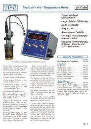
900-C Conductivity, TDS, Resistivity, Ratio, Meter - TPS
900-C Conductivity, TDS, Resistivity, Ratio, Meter - TPS
900-C Conductivity, TDS, Resistivity, Ratio, Meter - TPS

You also want an ePaper? Increase the reach of your titles
YUMPU automatically turns print PDFs into web optimized ePapers that Google loves.
1.3 Menu and Function KeysPress the to function keys to select desired options within the menu system.Additionally, these keys perform the following function directly in normal measurement mode…: Press to record readings into the Notepad. See section 9.: Press to change up one range at a time, when the <strong>900</strong>-C is in manual ranging mode.See section 17.1.: Press to start or stop automatic datalogging. See section 10.Alternatively, press to transmit current reading plus date and time to the optional RS232port. See section 11.2.: Press to change down one range at a time, when the <strong>900</strong>-C is in manual ranging mode.See section 17.1.: Press to alternate between Automatic and Manual ranging when the <strong>900</strong>-C is in normalmeasurement mode.Press to obtain context-sensitive help messages where available. This function is disabledwithin menus.1.4 Numeric KeypadUsed to enter values during set-up and calibration. A negative sign and decimal point are provided.1.5 Enter KeyPress the key to accept default values or those entered on the Numeric Keypad.1.6 Delete KeyPress the key to make corrections to values entered on the Numeric Keypad.Press and hold this key at turn-on to initialise the <strong>900</strong>-C. See section 14.1.7 80 Character Display80 character alphanumeric display with user-friendly menu and context-sensitive help system.Shows <strong>Conductivity</strong>/<strong>TDS</strong>/<strong>Resistivity</strong>/<strong>Ratio</strong>, Temperature, Date and Time simultaneously.5
61.8 Unpacking InformationBefore using your new <strong>900</strong>-C, please check that the following accessories have been included:Part NoStandard Kit…1. <strong>900</strong>-C <strong>Conductivity</strong>/<strong>TDS</strong>/<strong>Resistivity</strong>/<strong>Ratio</strong> <strong>Meter</strong> .... 1221022. k=1.0 <strong>Conductivity</strong> Sensor ....................................... 1222063. Temperature/ATC Sensor......................................... 1212454. 2.76mS/cm <strong>Conductivity</strong> Standard, 200mL .............. 1223065. Plug-Pack Power Supply .......................................... 1300446. <strong>900</strong>-C Handbook...................................................... 130050Options that may have been ordered with your <strong>900</strong>-C…1. Flexible arm type electrode holder............................ 1300882. RS232 Serial Interface Option (includes cable)......... 1300293. Recorder Output Option (includes cable).................. 1300284. RS232 PLUS Recorder Output Option...................... 130049(includes cable)5. Communication software for Windows 3.1,.............. 13008695, and NT6. Communication software for DOS ........................... 1300757. RS232 Printer........................................................... 1300318. Platinizing solution, 20mL........................................ 122300Optional Sensors…1. k=0.1 <strong>Conductivity</strong> Sensor ....................................... 1222042. k=10 <strong>Conductivity</strong> Sensor ........................................ 1222023. k=0.1 <strong>Conductivity</strong> + Temperature Sensor ............... 1222254. k=1.0 <strong>Conductivity</strong> + Temperature Sensor ............... 1222275. k=10 <strong>Conductivity</strong> + Temperature Sensor ................ 1222236.Other spares…7. RS232 Interface Cable.............................................. 1300228. Recorder Cable......................................................... 1300219. RS232 PLUS Recorder Cable................................... 130030
71.9 SpecificationsRangesMode k=0.1 Sensor k=1.0 Sensor k=10 Sensor User k factor<strong>Conductivity</strong>,Siemens/cm0 to 2.000 µS/cm0 to 20.00 µS/cm0 to 200.0 µS/cm0 to 2000 µS/cm0 to 20.00 mS/cm0 to 20.00 µS/cm0 to 200.0 µS/cm0 to 2000 µS/cm0 to 20.00 mS/cm0 to 200.0 mS/cm0 to 200.0 µS/cm0 to 2000 µS/cm0 to 20.00 mS/cm0 to 200.0 mS/cm0 to 2000 mS/cm5 ranges,depending onactual k factor<strong>Conductivity</strong>,Siemens/metre0 to 200.0 µS/m0 to 2000. µS/m0 to 20.00 mS/m0 to 200.0 mS/m0 to 2000 mS/m0 to 2000. µS/m0 to 20.00 mS/m0 to 200.0 mS/m0 to 2000 mS/m0 to 20.00 S/m0 to 20.00 mS/m0 to 200.0 mS/m0 to 2000 mS/m0 to 20.00 S/m0 to 200.0 S/m5 ranges,depending onactual k factor<strong>TDS</strong>0 to 1.000 ppM0 to 10.00 ppM0 to 100.0 ppM0 to 1000 ppM0 to 10.00 ppK0 to 10.00 ppM0 to 100.0 ppM0 to 1000 ppM0 to 10.00 ppM0 to 100.0 ppM0 to 100.0 ppM0 to 1000 ppM0 to 10.00 ppK0 to 100.0 ppK0 to 1000 ppK5 ranges,depending onactual k factor<strong>Resistivity</strong> 0.50 to 99.99MΩ.cm50 to 9999KΩ.cm5.0 to 999.9KΩ.cm0.50 to 99.99KΩ.cm50 to 9999Ω.cm50 to 9999.KΩ.cm5.0 to 999.9KΩ.cm0.50 to 99.99KΩ.cm50 to 9999Ω.cm5.0 to 999.9Ω.cm5.0 to 999.9KΩ.cm0.50 to 99.99KΩ.cm50 to 9999Ω.cm5.0 to 999.9Ω.cm0.50 to 99.99Ω.cm5 ranges,depending onactual k factor<strong>Ratio</strong> 0.000 to approx1.5001.50 to approx15.00(depending on spanof sensor)0.000 to approx1.5001.50 to approx15.00(depending on spanof sensor)0.000 to approx1.5001.50 to approx15.00(depending on spanof sensor)<strong>Ratio</strong> mode notavailable for userk factor.TemperatureRangeResolutionAccuracyCalibrationTemp. Sensor Offset RangeGeneral SpecificationsTemperature CompensationCond. Sensor Span RangeMemoryAutomatic LoggingRS232 Port (optional)ClockGood Laboratory PracticesPowerDimensions: -10.0 to 120.0 O C: 0.1 O C: ±0.2 O C: Automatic calibration: -10.0 O C to +10.0 O C: Automatic, 0 to 100 O C: k=0.1 Sensor : k=0.075 to k=0.133k=1.0 Sensor : k=0.75 to k=1.33k=10 Sensor : k=7.5 to k=13.3User k factor : ±25% of nominated k factor: 2300 readings including date and time: User-set for one reading every 1 to 90 seconds, minutes or hours.: 300, 1200 & 9600 baud.8 bits, no parity, 1 stop bit, XON/XOFF Protocol.: Calendar clock displays date, month, year, hours, minutes & seconds.: Date, Time and Value of last <strong>Conductivity</strong>, <strong>TDS</strong>, <strong>Resistivity</strong>, <strong>Ratio</strong> andTemperature calibration are stored separately for k=0.1, k=1.0, k=10and user-selected k factor sensors. This information can be recalled orsent to the optional RS232 port at any time.: 12V DC, 50mA. Plug-pack power supply is included in standard kit.: 270 x 210 x 75 mm
8Mass : Instrument only : Approx. 1.0 kgFull Kit : Approx. 3.0 kgEnvironment Temperature : 0 to 45 O CHumidity : 0 to 90 % R.H.
2. <strong>900</strong>-C Menu StructureA detailed breakdown of the menu system of the <strong>900</strong>-C is shown below. This diagram provides aquick reference for the menu functions available for the <strong>900</strong>-C.Press the function keys in normal display mode, to perform the following tasks:: Press to record readings into the Notepad. See section 9.: Press to change up one range at a time, when the <strong>900</strong>-C is in manual ranging mode.See section 17.1.: Press to start or stop automatic datalogging. See section 10.If logging period is set to zero, press to transmit current reading plus date and time to theoptional RS232 port. See section 11.2.: Press to change down one range at a time, when the <strong>900</strong>-C is in manual ranging mode.See section 17.1.: Press to alternate between Automatic and Manual ranging when the <strong>900</strong>-C is in normalmeasurement mode.Press to obtain context-sensitive help messages where available. This function is disabledwithin menus.: Press to access the user-friendly menu system, as detailed over the page.9
10<strong>900</strong>-C Menu Structure…→ F1:Calibrate → F1:<strong>Conductivity</strong>or: F1:<strong>TDS</strong>or: F1:<strong>Resistivity</strong>or: F1:<strong>Ratio</strong>F2:Temperature→ F2:Notepad → F1:RecallF2:Erase → F1:Erase AllF2:Erase LastF3:Print *F4:Program → F1:SecsF2:MinsF3:Hours→ F3:Mode → F1:<strong>Conductivity</strong>F2:<strong>Resistivity</strong>F3:<strong>TDS</strong>F4:<strong>Ratio</strong>F5:Platinizer → F1:k=.1F2:k=1F3:k=10→ F4:Setup → F1:Ports * → F1:300F2:1200F3:9600F2:ClockF3:GLP → F1:RecallF3:Print *→ F5:Configure → F1:Units → F1:S/cm (Cond mode)* These functions available when RS232 Port option is fitted.orF2:S/m (Cond mode)F1:NaCl (<strong>TDS</strong> mode)F2:KCl (<strong>TDS</strong> mode)F2:Standard → Enter Standard.F3:ATC → F1:SampleF2:StandardF3:25 O cF4:20 O cF5:k factor → Enter k factor
3. <strong>Conductivity</strong> Mode3.1 Selecting <strong>Conductivity</strong> Mode1. Select <strong>Conductivity</strong> Mode ( → F3:Mode → F1:<strong>Conductivity</strong>).2. The <strong>900</strong>-C now proceeds to <strong>Conductivity</strong> measurement mode. Note that the decimal point willbe replaced by a “ ∗ ” until a successful calibration has been performed (see section 3.8).3.2 Selecting <strong>Conductivity</strong> readout unitsThe factory default setting for this item is S/cm. If this is satisfactory, go directly to section 3.3.1. Select the Display Units configuration menu ( → F5:Configure → F1:Units).2. Press to display <strong>Conductivity</strong> in units of S/cm (Siemens per centimetre).Press to display <strong>Conductivity</strong> in units of S/m (Siemens per metre).Press to quit without changing the current setting.3.3 Setting the <strong>Conductivity</strong> calibration standardThe factory default for this item is 2.76mS/cm. If this is satisfactory, go directly to section 3.4.1. Select the <strong>Conductivity</strong> Standard entry ( → F5:Configure → F2:Standard).The following screen is now displayed…<strong>Conductivity</strong> Standard:2760 uS/cmRange 20uS/cm to 2000mS/cm {2760}2. Type in the value of the <strong>Conductivity</strong> standard that is to be used for calibration, including thedecimal point. Use the key to make any corrections. Be sure to enter the value of thestandard at the selected reference temperature (see section 3.4).3. Press to save the value of the standard solution.Alternatively, press to quit without changing the current setting.4. The <strong>900</strong>-C will now ask you to enter the units for the <strong>Conductivity</strong> standard…<strong>Conductivity</strong> Standard:2760Select Units F1:uS/cm F2:mS/cm5. (a) If the <strong>900</strong>-C is set up for S/cm (section 3.2)…Press to set the <strong>Conductivity</strong> Standard as µS/cm.Press to set the <strong>Conductivity</strong> Standard as mS/cm.or (b) If the <strong>900</strong>-C is set up for S/m (section 3.2)…Press to set the <strong>Conductivity</strong> Standard as µS/m.Press to set the <strong>Conductivity</strong> Standard as mS/m.Press to set the <strong>Conductivity</strong> Standard as S/m.6. The <strong>Conductivity</strong> standard is now programmed for use at calibration.3.4 Setting the Reference TemperatureThe factory default setting for this item is 25 O C. If this is satisfactory, go directly to section 3.5.1. Select the ATC configuration menu ( → F5:Configure → F3:ATC).2. Press to reference all readings to 25 O C for Automatic Temperature Compensation.Press to reference all readings to 20 O C for Automatic Temperature Compensation.Press to quit without changing the current setting.11
123.5 Setting the ATC Slope for unknown samplesThe factory default setting for this item is 2.00 %/ O C. If this is satisfactory, go directly to section3.6.The ATC Slope for the unknown sample solution is the rate at which the conductivity of thesolution changes per degree Celsius. This Slope must be set correctly on the <strong>900</strong>-C to enable theAutomatic Temperature Compensation system to work correctly. If the ATC Slope is not known,please refer to section 17.3 for details on how it can be calculated.To set the ATC Slope for unknown samples…1. Select ATC Slope entry ( → F5:Configure → F3:ATC → F1:Sample).The following screen is displayed…A.T.C. Slope of unknown:2.00%2. Type in the ATC Slope of the unknown sample, including the decimal point. Use the key tomake any corrections. Enter 0.00% to obtain absolute readings, without temperature correction.3. Press to save the ATC Slope of the unknown solution.Alternatively, press to quit without changing the current setting.3.6 Setting the ATC Slope for the Calibration StandardThe factory default setting for this item is 2.00 %/ O C. If this is satisfactory, go directly to section3.7.The ATC Slope for the Calibration standard is the rate at which the conductivity of the solutionchanges per degree Celsius. This Slope must be set correctly on the <strong>900</strong>-C to enable the AutomaticTemperature Compensation system to work correctly. If the ATC Slope is not known, please referto section 17.3 for details on how it can be calculated.To set the ATC Slope for the Calibration Standard…1. Select ATC Slope entry for the Calibration Standard,( → F5:Configure → F3:ATC → F2:Standard).The following screen is displayed…A.T.C. Slope of Standard:2.00%2. Type in the ATC Slope of the Calibration Standard, including the decimal point. Use thekey to make any corrections. Enter 0.00% for absolute readings, without temperaturecorrection.3. Press to save the ATC Slope of the Calibration Standard.Alternatively, press to quit without changing the current setting.
3.7 Setting the <strong>Conductivity</strong> sensor k factorThe <strong>900</strong>-C automatically recognises the k factor for genuine <strong>TPS</strong> k=0.1, k=1.0 and k=10 sensors.If one of these sensors is being used, then go directly to section 3.8.1. Select k factor entry ( → F5:Configure → F4:k factor).2. The k factor entry screen is now displayed…Enter k Factor:1.000133. Enter the nominal k factor of the non-standard sensor using the numeric keypad. Use thekey to make any corrections.4. Press to save the k factor of the non-standard sensor.Alternatively, press to quit without changing the current setting.Notes1. The allowable range of k factors for non-standard sensors is k=0.005 to k=30.00.2. The exact k factor of the non-standard sensor is determined during calibration (section 3.8).3. Manual k factor entry is not available for <strong>TPS</strong> k=0.1, k=1.0 and k=10 sensors. The exact kfactor for these sensors is determined during calibration (section 3.8).
143.8 <strong>Conductivity</strong> CalibrationBefore attempting a <strong>Conductivity</strong> calibration, ensure that the <strong>900</strong>-C has been set up correctly,according to sections 3.1 to 3.7. The calibration procedure detailed below uses the sampleconfigurations shown in sections 3.1 to 3.7.Also ensure that Temperature has been correctly calibrated (see section 7.1). A “ ∗ ” in theTemperature readout in place of the decimal point indicates that Temperature is NOT calibrated.1. Plug the <strong>Conductivity</strong> sensor into the CELL socket and the temperature sensor into the TEMPsocket. (The separate temperature sensor is not required for combination<strong>Conductivity</strong>/Temperature sensors.)2. Rinse the <strong>Conductivity</strong> and temperature sensors in distilled water. Shake off as much water aspossible. Blot the outside of the sensor dry. DO NOT BLOT THE ELECTRODE PLATES.Zero Calibration3. Let the sensor dry in air.4. Select <strong>Conductivity</strong> Calibration ( → F1:Calibrate → F1:<strong>Conductivity</strong>).5. The <strong>900</strong>-C will recognise the low conductivity signal and attempt a Zero calibration. Forexample…0*01uS/cm k=1*00 25.0 O cPress Enter to Zero probe or Menu Exit.6. When the reading has stabilised at or near zero, press to calibrate or to quit. The ∗will not be removed after a zero calibration.Standard Calibration7. Place the <strong>Conductivity</strong> sensor into a sample of <strong>Conductivity</strong> standard, so that it is immersedcorrectly, with adequate clearance to the floor and walls of the vessel. See section 17.2 fordetails of correct sensor immersion.DO NOT place the sensor directly into the bottle of standard. Discard the used sample ofstandard after use.Select <strong>Conductivity</strong> Calibration ( → F1:Calibrate → F1:<strong>Conductivity</strong>). Thecalibration screen will be displayed, with the <strong>Conductivity</strong> standard to be used. For example…2750*uS/cm k=1*00 25.0 O cPress Enter to Calibrate. STD=2760 uS/cm8. When the reading has stabilised, press to calibrate. The ∗ will now be replaced by adecimal point, if calibration was successful.9. The <strong>900</strong>-C is now calibrated for <strong>Conductivity</strong> and is ready for use in this mode.
3.9 <strong>Conductivity</strong> Calibration Notes1. A Zero calibration should be performed at least monthly. In low conductivity applications(where a zero error is particularly significant) a zero calibration may have to be done weekly.2. A Standard calibration should be performed at least weekly. Of course, more frequentcalibration will result in greater confidence in results.3. <strong>Conductivity</strong>, <strong>TDS</strong>, <strong>Resistivity</strong> and <strong>Ratio</strong> calibration data is stored separately in memory.Ensure that the <strong>900</strong>-C has been correctly calibrated for the mode in which it will be used. The<strong>900</strong>-C does not require re-calibration when alternating between <strong>Conductivity</strong>, <strong>TDS</strong>, <strong>Resistivity</strong>and <strong>Ratio</strong> modes, providing the instrument has been correctly calibrated for each mode.4. All calibration information is retained in memory when the <strong>900</strong>-C is switched off, even whenthe power supply is unplugged. This information can be recalled or printed later using the GLPfunction (see section 8).5. The <strong>900</strong>-C displays the value of the standard to which it will attempt to calibrate. Ensure thatthe standard value displayed corresponds to the standard that you are using. Alter the Standardsset-up if necessary (see section 3.3).3.10 <strong>Conductivity</strong> Calibration Messages1. If a Zero Calibration has been successfully performed, the <strong>900</strong>-C will display the followingmessage…Zero ok152. If a Standard Calibration has been successfully performed, the <strong>900</strong>-C will display the followingmessage, and the calculated k factor of the sensor. For example…Calibration ok. Calculated k=1.083. If a Standard Calibration has failed, the <strong>900</strong>-C will display the following message, and thecalculated k factor of the sensor. For example…Calibrate Failure. Check STD=2760 uS/cmCalc. K=3.64, Exceeds Limit.Notes1. The allowable k factor range is +/-25% of nominal. This range is ample to allow for correctlyfunctioning <strong>Conductivity</strong> sensors. If calibration fails due to the k factor being outside theselimits, then please consult the Troubleshooting guide (section 16.2) for possible remedies.
164. <strong>TDS</strong> Mode4.1 Selecting <strong>TDS</strong> Mode1. Select <strong>TDS</strong> Mode ( → F3:Mode → F3:<strong>TDS</strong>).2. The <strong>900</strong>-C now proceeds to <strong>TDS</strong> measurement mode. Note that the decimal point will bereplaced by a “ ∗ ” until a successful calibration has been performed (see section 4.8).4.2 Selecting <strong>TDS</strong> readout in terms of NaCl or KClThe factory default setting for this item is NaCl. If this is satisfactory, go directly to section 4.3.1. Select the Display Units configuration menu ( → F5:Configure → F1:Units).2. Press to display <strong>TDS</strong> in terms of NaCl (Sodium Chloride).Press to display <strong>TDS</strong> in terms of KCl Potassium Chloride).Press to quit without changing the current setting.NoteThe difference between the NaCl and KCl settings is the formula used for converting the<strong>Conductivity</strong> reading from the sensor to a <strong>TDS</strong> reading. Set this function for the predominant salt inthe sample solution. All <strong>TPS</strong> <strong>TDS</strong> and Salinity standards are made up using NaCl.4.3 Setting the <strong>TDS</strong> calibration standardThe factory default for this item is 2000 ppM. If this is satisfactory, go directly to section 4.4.1. Select the <strong>TDS</strong> Standard entry ( → F5:Configure → F2:Standard).The following screen is now displayed…<strong>TDS</strong> Standard:2000 ppMRange 20 ppM to 500 ppK {2000}2. Type in the value of the <strong>TDS</strong> standard that is to be used for calibration, including the decimalpoint. Use the key to make any corrections. Be sure to enter the value of the standard at theselected reference temperature (see section 4.4).3. Press to save the value of the standard solution.Alternatively, press to quit without changing the current setting.4. The <strong>900</strong>-C will now ask you to enter the units for the <strong>TDS</strong> standard…<strong>TDS</strong> Standard:1000Select Units F1:ppMF2:ppK5. The <strong>TDS</strong> standard is now programmed for use at calibration.4.4 Setting the Reference TemperatureThe factory default setting for this item is 25 O C. If this is satisfactory, go directly to section 4.5.1. Select the ATC configuration menu ( → F5:Configure → F3:ATC).2. Press to reference all readings to 25 O C for Automatic Temperature Compensation.Press to reference all readings to 20 O C for Automatic Temperature Compensation.Press to quit without changing the current setting.
4.5 Setting the ATC Slope for unknown samplesThe factory default setting for this item is 2.00 %/ O C. If this is satisfactory, go directly to section4.6.The ATC Slope for the unknown sample solution is the rate at which the <strong>TDS</strong> of the solutionchanges per degree Celsius. This Slope must be set correctly on the <strong>900</strong>-C to enable the AutomaticTemperature Compensation system to work correctly. If the ATC Slope is not known, please referto section 17.3 for details on how it can be calculated.To set the ATC Slope for unknown samples…1. Select ATC Slope entry ( → F5:Configure → F3:ATC → F1:Sample).The following screen is displayed…A.T.C. Slope of unknown:2.00%172. Type in the ATC Slope of the unknown sample, including the decimal point. Use the key tomake any corrections. Enter 0.00% to obtain absolute readings, without temperature correction.3. Press to save the ATC Slope of the unknown solution.Alternatively, press to quit without changing the current setting.4.6 Setting the ATC Slope for the Calibration StandardThe factory default setting for this item is 2.00 %/ O C. If this is satisfactory, go directly to section4.7.The ATC Slope for the Calibration standard is the rate at which the <strong>TDS</strong> of the solution changes perdegree Celsius. This Slope must be set correctly on the <strong>900</strong>-C to enable the Automatic TemperatureCompensation system to work correctly. If the ATC Slope is not known, please refer to section 17.3for details on how it can be calculated.To set the ATC Slope for the Calibration Standard…1. Select ATC Slope entry for the Calibration Standard,( → F5:Configure → F3:ATC → F2:Standard).The following screen is displayed…A.T.C. Slope of Standard:2.00%2. Type in the ATC Slope of the Calibration Standard, including the decimal point. Use thekey to make any corrections. Enter 0.00% for absolute readings, without temperaturecorrection.3. Press to save the ATC Slope of the Calibration Standard.Alternatively, press to quit without changing the current setting.
184.7 Setting the <strong>TDS</strong> sensor k factorThe <strong>900</strong>-C automatically recognises the k factor for genuine <strong>TPS</strong> k=0.1, k=1.0 and k=10 sensors.If one of these sensors is being used, then go directly to section 4.8.1. Select k factor entry ( → F5:Configure → F4:k factor).2. The k factor entry screen is now displayed…Enter k Factor:1.0003. Enter the nominal k factor of the non-standard sensor using the numeric keypad. Use thekey to make any corrections.4. Press to save the k factor of the non-standard sensor.Alternatively, press to quit without changing the current setting.Notes1. The allowable range of k factors for non-standard sensors is k=0.005 to k=30.00.2. The exact k factor of the non-standard sensor is determined during calibration (section 4.8).3. Manual k factor entry is not available for <strong>TPS</strong> k=0.1, k=1.0 and k=10 sensors. The exact kfactor for these sensors is determined during calibration (section 4.8).
4.8 <strong>TDS</strong> CalibrationBefore attempting a <strong>TDS</strong> calibration, ensure that the <strong>900</strong>-C has been set up correctly, according tosections 4.1 to 4.7. The calibration procedure detailed below uses the sample configurations shownin sections 4.1 to 4.7.Also ensure that Temperature has been correctly calibrated (see section 7.1). A “ ∗ ” in theTemperature readout in place of the decimal point indicates that Temperature is NOT calibrated.1. Plug the <strong>TDS</strong> sensor into the CELL socket and the temperature sensor into the TEMP socket.(The separate temperature sensor is not required for combination <strong>TDS</strong>/Temperature sensors.)2. Rinse the <strong>TDS</strong> and temperature sensors in distilled water. Shake off as much water as possible.Blot the outside of the sensor dry. DO NOT BLOT THE ELECTRODE PLATES.Zero Calibration3. Let the sensor dry in air.4. Select <strong>TDS</strong> Calibration ( → F1:Calibrate → F1:<strong>TDS</strong>).5. The <strong>900</strong>-C will recognise the low <strong>TDS</strong> signal and attempt a Zero calibration. For example…0*01ppM k=1*00 25.0 O cPress Enter to Zero probe or Menu Exit.6. When the reading has stabilised at or near zero, press to calibrate or to quit. The ∗will not be removed after a zero calibration.Standard Calibration7. Place the <strong>TDS</strong> sensor into a sample of <strong>TDS</strong> standard, so that it is immersed correctly, withadequate clearance to the floor and walls of the vessel. See section 17.2 for details of correctsensor immersion.DO NOT place the sensor directly into the bottle of standard. Discard the used sample ofstandard after use.Select <strong>TDS</strong> Calibration ( → F1:Calibrate → F1:<strong>TDS</strong>). The calibration screen willbe displayed, with the <strong>TDS</strong> standard to be used. For example…2000*ppM k=1*00 25.0 O cPress Enter to Calibrate. STD=2000 ppM.8. When the reading has stabilised, press to calibrate. The ∗ will now be replaced by adecimal point, if calibration was successful.9. The <strong>900</strong>-C is now calibrated for <strong>TDS</strong> and is ready for use in this mode.19
204.9 <strong>TDS</strong> Calibration Notes1. A Zero calibration should be performed at least monthly. In low <strong>TDS</strong> applications (where azero error is particularly significant) a zero calibration may have to be done weekly.2. A Standard calibration should be performed at least weekly. Of course, more frequentcalibration will result in greater confidence in results.3. <strong>Conductivity</strong>, <strong>TDS</strong>, <strong>Resistivity</strong> and <strong>Ratio</strong> calibration data is stored separately in memory.Ensure that the <strong>900</strong>-C has been correctly calibrated for the mode in which it will be used. The<strong>900</strong>-C does not require re-calibration when alternating between <strong>Conductivity</strong>, <strong>TDS</strong>, <strong>Resistivity</strong>and <strong>Ratio</strong> modes, providing the instrument has been correctly calibrated for each mode.4. All calibration information is retained in memory when the <strong>900</strong>-C is switched off, even whenthe power supply is unplugged. This information can be recalled or printed later using the GLPfunction (see section 8).5. The <strong>900</strong>-C displays the value of the standard to which it will attempt to calibrate. Ensure thatthe standard value displayed corresponds to the standard that you are using. Alter the Standardsset-up if necessary (see section 4.3).4.10 <strong>TDS</strong> Calibration Messages1. If a Zero Calibration has been successfully performed, the <strong>900</strong>-C will display the followingmessage…Zero ok2. If a Standard Calibration has been successfully performed, the <strong>900</strong>-C will display the followingmessage, and the calculated k factor of the sensor. For example…Calibration ok. Calculated k=1.083. If a Standard Calibration has failed, the <strong>900</strong>-C will display the following message, and thecalculated k factor of the sensor. For example…NotesCalibrate Failure. Check STD=2000 ppMCalc. K=3.64, Exceeds Limit.1. The allowable k factor range is +/-25% of nominal. This range is ample to allow for correctlyfunctioning <strong>TDS</strong> sensors. If calibration fails due to the k factor being outside these limits, thenplease consult the Troubleshooting guide (section 16.2) for possible remedies.
5. <strong>Resistivity</strong> Mode5.1 Selecting <strong>Resistivity</strong> Mode1. Select <strong>Resistivity</strong> Mode ( → F3:Mode → F2:<strong>Resistivity</strong>).2. The <strong>900</strong>-C now proceeds to <strong>Resistivity</strong> measurement mode. Note that the decimal point will bereplaced by a “ ∗ ” until a successful calibration has been performed (see section 5.7).5.2 Setting the <strong>Resistivity</strong> calibration standardThe factory default for this item is 362.3 Ω.cm (the resistivity value of 2.76mS/cm standard). Ifthis is satisfactory, go directly to section 5.3.1. Select the <strong>Resistivity</strong> Standard entry ( → F5:Configure → F2:Standard).The following screen is now displayed…<strong>Resistivity</strong> Standard:362.3Ω.cm.cmRange 5Ω.cm to 50KΩ.cm {362.3}2. Type in the value of the <strong>Resistivity</strong> standard that is to be used for calibration, including thedecimal point. Use the key to make any corrections. Be sure to enter the value of thestandard at the selected reference temperature (see section 5.3).3. Press to save the value of the standard solution.Alternatively, press to quit without changing the current setting.4. The <strong>900</strong>-C will now ask you to enter the units for the <strong>Resistivity</strong> standard…<strong>Resistivity</strong> Standard:362.3Select Units F1:Ω.cm F2:KΩ.cm5. The <strong>Resistivity</strong> standard is now programmed for use at calibration.5.3 Setting the Reference TemperatureThe factory default setting for this item is 25 O C. If this is satisfactory, go directly to section 5.4.1. Select the ATC configuration menu ( → F5:Configure → F3:ATC).2. Press to reference all readings to 25 O C for Automatic Temperature Compensation.Press to reference all readings to 20 O C for Automatic Temperature Compensation.Press to quit without changing the current setting.21
225.4 Setting the ATC Slope for unknown samplesThe factory default setting for this item is 2.00 %/ O C. If this is satisfactory, go directly to section5.5.The ATC Slope for the unknown sample solution is the rate at which the resistivity of the solutionchanges per degree Celsius. This Slope must be set correctly on the <strong>900</strong>-C to enable the AutomaticTemperature Compensation system to work correctly. If the ATC Slope is not known, please referto section 17.3 for details on how it can be calculated.To set the ATC Slope for unknown samples…1. Select ATC Slope entry ( → F5:Configure → F3:ATC → F1:Sample).The following screen is displayed…A.T.C. Slope of unknown:2.00%2. Type in the ATC Slope of the unknown sample, including the decimal point. Use the key tomake any corrections. Enter 0.00% to obtain absolute readings, without temperature correction.3. Press to save the ATC Slope of the unknown solution.Alternatively, press to quit without changing the current setting.5.5 Setting the ATC Slope for the Calibration StandardThe factory default setting for this item is 2.00 %/ O C. If this is satisfactory, go directly to section5.6.The ATC Slope for the Calibration standard is the rate at which the resistivity of the solutionchanges per degree Celsius. This Slope must be set correctly on the <strong>900</strong>-C to enable the AutomaticTemperature Compensation system to work correctly. If the ATC Slope is not known, please referto section 17.3 for details on how it can be calculated.To set the ATC Slope for the Calibration Standard…1. Select ATC Slope entry for the Calibration Standard,( → F5:Configure → F3:ATC → F2:Standard).The following screen is displayed…A.T.C. Slope of Standard:2.00%2. Type in the ATC Slope of the Calibration Standard, including the decimal point. Use thekey to make any corrections. Enter 0.00% for absolute readings, without temperaturecorrection.3. Press to save the ATC Slope of the Calibration Standard.Alternatively, press to quit without changing the current setting.
5.6 Setting the <strong>Resistivity</strong> sensor k factorThe <strong>900</strong>-C automatically recognises the k factor for genuine <strong>TPS</strong> k=0.1, k=1.0 and k=10 sensors.If one of these sensors is being used, then go directly to section 5.7.1. Select k factor entry ( → F5:Configure → F4:k factor).2. The k factor entry screen is now displayed…Enter k Factor:1.000233. Enter the nominal k factor of the non-standard sensor using the numeric keypad. Use thekey to make any corrections.4. Press to save the k factor of the non-standard sensor.Alternatively, press to quit without changing the current setting.Notes1. The allowable range of k factors for non-standard sensors is k=0.005 to k=30.00.2. The exact k factor of the non-standard sensor is determined during calibration (section 5.7).3. Manual k factor entry is not available for <strong>TPS</strong> k=0.1, k=1.0 and k=10 sensors. The exact kfactor for these sensors is determined during calibration (section 5.7).
245.7 <strong>Resistivity</strong> CalibrationBefore attempting a <strong>Resistivity</strong> calibration, ensure that the <strong>900</strong>-C has been set up correctly,according to sections 5.1 to 5.6. The calibration procedure detailed below uses the sampleconfigurations shown in sections 5.1 to 5.6.Also ensure that Temperature has been correctly calibrated (see section 7.1). A “ ∗ ” in theTemperature readout in place of the decimal point indicates that Temperature is NOT calibrated.1. Plug the <strong>Resistivity</strong> sensor into the CELL socket and the temperature sensor into the TEMPsocket. (The separate temperature sensor is not required for combination<strong>Resistivity</strong>/Temperature sensors.)2. Rinse the <strong>Resistivity</strong> and temperature sensors in distilled water. Shake off as much water aspossible. Blot the outside of the sensor dry. DO NOT BLOT THE ELECTRODE PLATES.Air Calibration3. Let the sensor dry in air.4. Select <strong>Resistivity</strong> Calibration ( → F1:Calibrate → F1:<strong>Resistivity</strong>).5. The <strong>900</strong>-C will recognise the Over-range resistivity signal and attempt an Air calibration. Forexample…Over-range k=1*00 25.0 O cPress Enter to Zero probe or Menu Exit.6. When the reading has stabilised at the Over-range reading, press to calibrate or toquit. The ∗ will not be removed after an Air calibration.Standard Calibration7. Place the <strong>Resistivity</strong> sensor into a sample of <strong>Resistivity</strong> standard, so that it is immersedcorrectly, with adequate clearance to the floor and walls of the vessel. See section 17.2 fordetails of correct sensor immersion.DO NOT place the sensor directly into the bottle of standard. Discard the used sample ofstandard after use.Select <strong>Resistivity</strong> Calibration ( → F1:Calibrate → F1:<strong>Resistivity</strong>). Thecalibration screen will be displayed, with the <strong>Resistivity</strong> standard to be used. For example…362* Ω.cm k=1*00 25.0 O cPress Enter to Calibrate. STD=362.3Ω.cm.cm8. When the reading has stabilised, press to calibrate. The ∗ will now be replaced by adecimal point, if calibration was successful.9. The <strong>900</strong>-C is now calibrated for <strong>Resistivity</strong> and is ready for use in this mode.
5.8 <strong>Resistivity</strong> Calibration Notes1. An Air calibration should be performed at least monthly. In high resistivity applications (wherea zero error is particularly significant) an Air calibration may have to be done weekly.2. A Standard calibration should be performed at least weekly. Of course, more frequentcalibration will result in greater confidence in results.3. <strong>Conductivity</strong>, <strong>TDS</strong>, <strong>Resistivity</strong> and <strong>Ratio</strong> calibration data is stored separately in memory.Ensure that the <strong>900</strong>-C has been correctly calibrated for the mode in which it will be used. The<strong>900</strong>-C does not require re-calibration when alternating between <strong>Conductivity</strong>, <strong>TDS</strong>, <strong>Resistivity</strong>and <strong>Ratio</strong> modes, providing the instrument has been correctly calibrated for each mode.4. All calibration information is retained in memory when the <strong>900</strong>-C is switched off, even whenthe power supply is unplugged. This information can be recalled or printed later using the GLPfunction (see section 8).5. The <strong>900</strong>-C displays the value of the standard to which it will attempt to calibrate. Ensure thatthe standard value displayed corresponds to the standard that you are using. Alter the Standardsset-up if necessary (see section 5.2).5.9 <strong>Resistivity</strong> Calibration Messages1. If an Air Calibration has been successfully performed, the <strong>900</strong>-C will display the followingmessage…Zero ok252. If a Standard Calibration has been successfully performed, the <strong>900</strong>-C will display the followingmessage, and the calculated k factor of the sensor. For example…Calibration ok. Calculated k=1.083. If a Standard Calibration has failed, the <strong>900</strong>-C will display the following message, and thecalculated k factor of the sensor. For example…NotesCalibrate Failure. Check STD=362.3Ω.cm.cmCalc. K=3.64, Exceeds Limit.1. The allowable k factor range is +/-25% of nominal. This range is ample to allow for correctlyfunctioning <strong>Resistivity</strong> sensors. If calibration fails due to the k factor being outside these limits,then please consult the Troubleshooting guide (section 16.2) for possible remedies.
266. <strong>Ratio</strong> Mode6.1 Selecting <strong>Ratio</strong> Mode1. Plug a <strong>TPS</strong> k=0.1, k=1.0 or k=10 sensor into the CELL socket. User k factor sensors cannot beused in <strong>Ratio</strong> mode.2. Plug a <strong>TPS</strong> sensor with the same k factor into the REFERENCE socket.3. Select <strong>Ratio</strong> Mode ( → F3:Mode → F4:<strong>Ratio</strong>).4. The <strong>900</strong>-C now performs a cell match check to ensure that the sensors have the same k factor.If this check fails, then the <strong>900</strong>-C will not proceed to <strong>Ratio</strong> mode. If this occurs, press , thenF3:Mode, and change back to <strong>Conductivity</strong>, <strong>TDS</strong> or <strong>Resistivity</strong> modes.5. The <strong>900</strong>-C now proceeds to ratio measurement mode. Note that the decimal point will bereplaced by a “ ∗ ” until a successful calibration has been performed (see section 6.2). Forexample…<strong>Ratio</strong> Cell/Ref 1*100k=1.0031/12/98 12:00:006.2 <strong>Ratio</strong> Calibration<strong>Ratio</strong> calibration involves placing both of the <strong>Conductivity</strong> sensors into the same value solution andsetting the ratio reading to 1.000.1. Ensure that matching k factor sensors have been plugged into the CELL and REFERENCEsockets, and <strong>Ratio</strong> mode has been selected (see section 6.1). A temperature sensor is notrequired for <strong>Ratio</strong> mode, but both solutions must be at the same temperature.2. Rinse the <strong>Conductivity</strong> sensors in distilled water. Shake off as much water as possible. Blot theoutside of the sensors dry. DO NOT BLOT THE ELECTRODE PLATES. Let the sensors dryin air.3. Place the two <strong>Conductivity</strong> sensors into two separate beakers of the same solution. The solutionthat is to be used as the reference for ratio measurements is generally the most ideal. Ensurethat the sensors are immersed correctly, with adequate clearance to the floor and walls of thevessel. See section 17.2 for details of correct sensor immersion.4. Select <strong>Ratio</strong> Calibration ( → F1:Calibrate → F1:<strong>Ratio</strong>).5. The <strong>900</strong>-C now checks that the sensors have the same k factor. The unit also checks that asuitable k factor is being used for the conductivity level of the reference solution. Thefollowing table details the acceptable limits of <strong>Conductivity</strong> for k=0.1, k=1.0 and k=10 sensors.All of these sensors will work to zero <strong>Conductivity</strong>, but accuracy below the recommendedminimum Conductivities listed will be diminished.Sensor k FactorRecommendedMinimum <strong>Conductivity</strong>k=0.1 0.1 uS/cm 10 mS/cmk=1.0 1 uS/cm 100 mS/cmk=10 10 uS/cm 1000 mS/cm6. The calibration screen is now displayed. For example…Maximum Limit of<strong>Conductivity</strong><strong>Ratio</strong> Cell/Ref 1*100k=1.00Press Enter to Calibrate
7. When the reading has stabilised, press to calibrate. The ∗ will now be replaced by adecimal point, if calibration was successful.8. The <strong>900</strong>-C is now calibrated for <strong>Ratio</strong> and is ready for use in this mode.6.3 <strong>Ratio</strong> Calibration Notes1. The two <strong>Conductivity</strong> sensors MUST be calibrated in separate containers, as they interfere witheach other.2. A <strong>Ratio</strong> calibration should be performed at least weekly. Of course, more frequent calibrationwill result in greater confidence in results.3. <strong>Conductivity</strong>, <strong>TDS</strong>, <strong>Resistivity</strong> and <strong>Ratio</strong> calibration data is stored separately to in memory.Ensure that the <strong>900</strong>-C has been correctly calibrated for the mode in which it will be used. The<strong>900</strong>-C does not require re-calibration when alternating between <strong>Conductivity</strong>, <strong>TDS</strong>, <strong>Resistivity</strong>and <strong>Ratio</strong> modes, providing the instrument has been correctly calibrated for each mode.4. All calibration information is retained in memory when the <strong>900</strong>-C is switched off, even whenthe power supply is unplugged. This information can be recalled or printed later using the GLPfunction (see section 8).5. The <strong>900</strong>-C checks that the sensors have the same k factor, and that a suitable k factor is beingused for the conductivity level of the solutions being measured whenever <strong>Ratio</strong> mode isselected and before every <strong>Ratio</strong> calibration.6.4 <strong>Ratio</strong> Calibration Messages1. If a <strong>Ratio</strong> Calibration has been successfully performed, the <strong>900</strong>-C will display the followingmessage and the calculated span difference between the two sensors…Calibrate OK, Delta Span = 1.100272. If a <strong>Ratio</strong> Calibration has failed, the <strong>900</strong>-C will display the following message, and the failedspan difference between the two sensors. For example…Calibrate Failed, Delta Gain > +/- 50%Check Cells, Ensure identical StandardsNotes1. The allowable difference in k factor between the two sensors is 50% to 200%. This range isample to allow for correctly functioning <strong>Conductivity</strong> sensors. If calibration fails due to the kfactor being outside these limits, then please consult the Troubleshooting guide (section 16.3)for possible remedies.
8. Good Laboratory Practices (GLP)The <strong>900</strong>-C keeps a record of the date and time of the last <strong>Conductivity</strong>, <strong>TDS</strong>, <strong>Resistivity</strong>, <strong>Ratio</strong> andTemperature calibrations as part of GLP guidelines. The calibration data for k=0.1, k=1.0, k=10 anduser k factor sensors are all stored separately.8.1 To recall GLP information on the display1. Switch the meter on.2. Select the GLP menu ( → F4:Setup → F3:GLP).3. Select F1:Recall from the menu.4. The instrument model, firmware version number, and instrument serial number are displayed,along with a prompt describing how to scroll through the GLP information.<strong>900</strong>C V3.0 R1234 @ 31/12/98 12:00F4:Next5. Press the key to sequentially scroll through the GLP information for all parameters. Pressthe key to scroll back to previous data. The sequence of information displayed is shownbelow. Press to abort at any time.GLP Display sequence…<strong>900</strong>C V3.0 R1234 @ 31/12/98 12:00F4:Next↑ ↓Cond Zero= 0.000uS/cm 31/12/98 09:00k=.1 Cond CalibratedF2:Back F4:Next↑ ↓Cond k=0.10 @ 150.0 uS/cm 31/12/98 09:10k=.1 Cond CalibratedF2:Back F4:Next↑ ↓<strong>TDS</strong> Zero= 0.000ppM 31/12/98 09:00k=.1 <strong>TDS</strong> CalibratedF2:Back F4:Next↑ ↓<strong>TDS</strong> k=0.10 @ 69.5ppM 31/12/98 09:20k=.1 <strong>TDS</strong> CalibratedF2:Back F4:Next↑ ↓Res. Zero OK 31/12/98 09:00k=.1 Res. CalibratedF2:Back F4:Next↑ ↓Res. k=0.10 @ 362.3Ω.cm .cm 31/12/98 09:30k=.1 Res. CalibratedF2:Back F4:Next↑ ↓The information listed above is repeatedfor k=1, k=10 and User k factor sensors.↑ ↓<strong>Ratio</strong> Delta Span 0.981 31/12/98 11:40<strong>Ratio</strong> Calibrated↑ ↓Temperature Offset=1.0 O c 31/12/98 11:50Temp. CalibratedF2:Back F4:Ends29
308.2 Failed CalibrationIf calibration has failed, the GLP function will reset the date and time for the failed calibration tozero. The <strong>900</strong>-C still shows the results for the last successful calibration, as shown in the followingexamples.1. Failed <strong>Conductivity</strong> span calibration for k=1.0 sensor…Cond k=1 @ 2760.uS/cm 00/00/00 00:00k=1 Un-Calibrated F2:Back F4:Next2. Failed Temperature Offset Calibration…Temperature Offset=1.0 O c 00/00/00 00:00Temp. Un-CalibratedF2:Back F4:Ends8.3 Printing GLP Information to the RS232 PortThe GLP information stored in the instrument’s memory can be sent to a printer or PC via theRS232 port. This function is available only when the optional RS232 port is fitted.1. Switch the meter on.2. Ensure that the <strong>900</strong>-C RS232 cable is connected to the instrument and to the printer or PC.3. Send the GLP information to the RS232 port:→ F4:Setup → F3:GLP → F3:PrintThe message “Printing GLP Data” is displayed while sending the data to the RS232 port.4. The GLP information is sent to the RS232 port in formatted ASCII text. For example…<strong>900</strong>C V3.0 S0000 @ 31/12/1998 12:00k=.1 Cond Zero= 0.000uS/cm @ 31/12/1998 09:00k=.1 Cond k=0.10 @ 150.0uS/cm @ 31/12/1998 09:10k=.1 <strong>TDS</strong> Zero= 0.000ppM @ 31/12/1998 09:00k=.1 <strong>TDS</strong> k=0.10 @ 69.5ppM @ 31/12/1998 09:20k=.1 Res. Zero OK @ 31/12/1998 09:00k=.1 Res. k=0.10 @ 6.67KOhms @ 31/12/1998 09:30k=1 Cond Zero= 0.00uS/cm @ 31/12/1998 09:40k=1 Cond k=1.00 @ 2760.uS/cm @ 31/12/1998 09:50k=1 <strong>TDS</strong> Zero= 0.00ppM @ 31/12/1998 09:40k=1 <strong>TDS</strong> k=1.00 @ 1452.ppM @ 31/12/1998 10:00k=1 Res. Zero OK @ 31/12/1998 09:40k=1 Res. k=1.00 @ 362.3_Ohms @ 31/12/1998 10:10k=10 Cond Zero= 0.0uS/cm @ 31/12/1998 10:20k=10 Cond k=10.0 @ 58.0mS/cm @ 31/12/1998 10:30k=10 <strong>TDS</strong> Zero= 0.0ppM @ 31/12/1998 10:20k=10 <strong>TDS</strong> k=10.0 @ 36.0ppK @ 31/12/1998 10:40k=10 Res. Zero OK @ 31/12/1998 10:20k=10 Res. k=10.0 @ 17.24_Ohms @ 31/12/1998 10:50User Cond Zero= 0.00uS/cm @ 31/12/1998 11:00User Cond k=5.00 @ 2760.uS/cm @ 31/12/1998 11:10User <strong>TDS</strong> Zero= 0.00ppM @ 31/12/1998 11:00User <strong>TDS</strong> k=5.00 @ 1452.ppM @ 31/12/1998 11:20User Res. Zero OK @ 31/12/1998 11:00User Res. k=5.00 @ 362.3_Ohms @ 31/12/1998 11:30<strong>Ratio</strong> Delta Span= 1.100 @ 31/12/1998 11:40Temperature Offset= 1.0oC @ 31/12/1998 11:50Ends
8.4 Instrument Serial NumberIn case the serial number that is fitted to the rear of the <strong>900</strong>-C is removed or becomes illegible, it isalso available on the <strong>900</strong>-C display.1. The serial number is displayed at turn-on, for example…<strong>900</strong>Csr V3.0 R1234 © 1998 <strong>TPS</strong> Pty Ltd<strong>Conductivity</strong>, <strong>TDS</strong>, <strong>Resistivity</strong>, <strong>Ratio</strong>The “s” after <strong>900</strong>C is shown when the RS232 serial Port option is fitted.The “r” after <strong>900</strong>C is shown when the Recorder Port option is fitted.2. The serial number is displayed when recalling the GLP information (section 8.1).3. The serial number is included on the printout of GLP information (section 8.3).4. The GLP information can be downloaded to a PC using the optional Windows ® software (partnumber 130086).8.5 Additional GLP FeaturesAnother GLP requirement is to record the date and time of every reading. The <strong>900</strong>-C does this foryou when readings are recorded either with the Notepad function (section 9) or the AutomaticLogging function (section 10).31
329. Notepad Function9.1 Recording Readings into the NotepadTo record readings into the Notepad memory…1. Press in normal display mode. The display should now look like this:2.76mS/cm k=1.00 25.0 O cLog# 1, Press F1 31/12/98 12:00:002. Press , to record <strong>Conductivity</strong>/<strong>TDS</strong>/<strong>Resistivity</strong>/<strong>Ratio</strong>, Temperature, Date and Time into thenotepad. This will be labelled as reading number 1.Alternatively, pressto quit without recording the reading.3. Repeat steps 1 & 2 as often as required. The maximum number of readings that can be stored inthe Notepad is 2300.9.2 Recalling Readings from the NotepadTo recall records from the Notepad onto the <strong>900</strong>-C display…1. Select the Notepad menu ( → F2:Notepad)2. Select F1:Recall from the menu.Record number 1 is now displayed.For example…2.76mS/cm k=1.00 25.0 O cLog#1 , F2:↑ F4:↓ 31/12/98 12:00:003. Press to display the next record.Pressto display the previous record.Press and hold or to roll rapidly through the readings.To display a specific record, type in the desired record number using the Numeric Keypad andpress .Pressto send the displayed record to the optional RS232 port.
339.3 Erasing Records from the NotepadTo erase records from the Notepad…1. Select the Erase Notepad menu ( → F2:Notepad → F2:Erase)2. The <strong>900</strong>-C now displays the Erase menu, for example…Erase Notepad, ( 100 ) Select OptionF1:Erase All F2:Erase Last Menu ExitsThe number of readings stored in the Notepad is displayed. See the “100” in the exampleabove.3. Press to erase all of the readings stored in the Notepad.PressPressto erase the last recorded reading only.to quit without erasing any records.9.4 Printing Records from the Notepad to the RS232 PortThis function is only available when the optional RS232 port is fitted.1. Connect one end of the RS232 cable to the RS232/Recorder socket of the <strong>900</strong>-C.2. Connect the other end of the RS232 cable to an RS232 Printer, or to the COM1 or COM2 portsof a PC.3. Ensure that the baud rate for the printer or PC and the <strong>900</strong>-C are the same. If necessary, alterthe baud rate of the <strong>900</strong>-C (see section 11.1).The <strong>900</strong>-C uses XON/XOFF protocol. Ensure that the printer is set accordingly.4. Select the Notepad menu. ( → F2:Notepad).5. Select F3:Print from the menu.6. Printing starts as soon as is pressed. The display shows the word “Printing” until printingis completed.
3410. Automatic DataloggingThe <strong>900</strong>-C can automatically log records into the Notepad. First the logging period must beprogrammed, then automatic logging can be started and stopped as required.1. Select the Notepad menu ( → F2:Notepad)2. Select F4:Program from the menu.The display should now look similar to that shown below. The current Logging/Printing Periodis displayed.Enter Logging/Printing Period : 0 secs3. Use the Numeric Keypad to set the period at which the <strong>900</strong>-C will automatically log recordsinto memory or to the RS232 port.PressPressto save the Logging/Printing Period.to quit without changing the current setting.4. After pressing , the <strong>900</strong>-C will ask you to enter the units. The Logging/Printing Periodyou have set is also displayed. For example…Logging/Printing Period : 2Select Units, F1:Secs, F2:Mins, F3:HoursPressPressPressto save the Logging/Printing Period as seconds.to save the Logging/Printing Period as minutes.to save the Logging/Printing Period as hours.5. If the optional RS232 port is fitted, the <strong>900</strong>-C will ask if the records are to be logged into theNotepad, or sent directly to the RS232 port. The display will look like this…F1:Log to Notepad F2:Send to RS232PressPressto log records into the Notepad (maximum of 2300 readings).to send records directly to the RS232 port.6. The automatic logging function is now programmed, and can be started and stopped asrequired.
357. To start automatic logging, press in normal display mode.When the <strong>900</strong>-C is logging into the Notepad, the display will look like this…2.76mS/cm k=1.00 25.0 O cLog# 1, 31/12/98 12:00:00The log number will increment and the <strong>900</strong>-C will beep each time a reading is recorded.If the <strong>900</strong>-C is sending records directly to the RS232 port, the display will look like this…2.76mS/cm k=1.00 25.0 O cSending 31/12/98 12:00:00The <strong>900</strong>-C will beep each time a record is sent to the RS232 port.8. Press to stop automatic logging.9. Note: The clock must be set before the <strong>900</strong>-C will allow automatic logging to start. Themessage “Clock Not Set” is displayed if the clock is not set. See section 13 for details onsetting the clock.
3611. RS232 PortThis section is applicable if the optional RS232 port is fitted.11.1 Setting the Baud Rate1. Select the Ports Set-up menu ( → F4:Setup → F1:Ports)2. The available baud rates are listed, along with the RS232 port configuration…Baud Rate: F1:300 F2:1200 >F3:96008 bits, No Parity, 1 Stop bit, XON/XOFFThe arrow indicates the current selection.3. Press to select 300 baud.PressPressPressto select 1200 baud.to select 9600 baud.to quit and retain the current setting.11.2 Sending Readings to the RS232 PortPress to instantly send readings to the RS232 port whenever the <strong>900</strong>-C is in normalmeasurement mode. This function is disabled if the automatic logging period is set to greater thanzero (see section 10).Records can be sent directly to the RS232 port rather than stored in memory during automaticdatalogging. See section 10 for details.Pressport.while recalling data on the display (see section 9.2) to send that record to the RS23211.3 RS232 ConfigurationThe <strong>900</strong>-C RS232 configuration is 8 Bits, No Parity, 1 Stop Bit, XON/XOFF Protocol.This information is displayed when setting the baud rate (see section 11.1)11.4 Communication and Statistical SoftwareCommunication between the <strong>900</strong>-C and a PC can be handled with any RS232 communicationsoftware. The diskette supplied by <strong>TPS</strong> contains a BASIC program for this purpose. A Windowsversion is also optionally available (part number 130086).Once the data is saved to disk, the next problem is how to use it. The data sent by the <strong>900</strong>-C isformatted in columns that can be imported by programs such as Microsoft ® Excel ® and Lotus 123 ® .Information on how to use the software is provided in the README files on the diskette.
11.5 CommandsThe following commands can be sent from a PC to the <strong>900</strong>-C. Note that denotes carriagereturn and denotes a line feed.Action Command NotesRequest current data ?D Returns the current <strong>Conductivity</strong>/<strong>TDS</strong>/<strong>Resistivity</strong>/<strong>Ratio</strong>,Temperature, date and time from the <strong>900</strong>-C. The log numberreturned is set to Zero.Request logged data ?R Returns all logged records from the <strong>900</strong>-C memory. Thedata ends with the message ENDSErase logged data ?E Erases all logged records from the <strong>900</strong>-C memory. Returnsthe message ERASED to confirm that the records havebeen erased.RequestinformationRequestinformationstatusGLP?S?GReturns the model name, firmware version number,instrument serial number and number of logged readings inmemory, for example…<strong>900</strong>CssV3.0sR1234s2300,where s are spaces. Note that the number of logged readingsis right-justified.Returns all calibration GLP information, plus the instrumentmodel, serial number and current date (see section 11.7 fordata format and handshaking).37
3811.6 Data FormatData is returned to the RS232 Port by the <strong>900</strong>-C in the following format…LLLL•DDDDDDUUUUUDDDDDDUUUUU•TTTTTuuu•dd/mm/yyyy•hh:mm:sswhere….LLLL• is one spaceDDDDDDUUUUUis the Log Number, 4 characters, right justified. The <strong>900</strong>-C sends a Zero forinstant readings (see section 11.2).is the <strong>Conductivity</strong>, <strong>TDS</strong>, <strong>Resistivity</strong> or <strong>Ratio</strong> data, 6 characters, right justified.is the unit description, which can be any one of the following…uS/cmmS/cmuS/M•mS/M•ppM••ppK••_OhmsKOhmsMOhms•••••(“•” is one space.)• is one space.TTTTTuuu• is one space.for µS/cm in <strong>Conductivity</strong> mode.for mS/cm in <strong>Conductivity</strong> mode.for µS/m in <strong>Conductivity</strong> mode.for mS/m in <strong>Conductivity</strong> mode.for Parts per Million in <strong>TDS</strong> mode.for Parts per Thousand in <strong>TDS</strong> mode.for Ohms in <strong>Resistivity</strong> mode.for Kilo Ohms in <strong>Resistivity</strong> mode.for Meg Ohms in <strong>Resistivity</strong> mode.in <strong>Ratio</strong> modeis Temperature data, 5 characters, right justified.is the unit description, sent as “oC• oC•”, where “•” is one space.dd/mm/yyyy is the date, month and year data. The year is sent as 4 digits for Year 2000compliance.• is one spacehh:mm:ssis the hours, minutes and seconds data.When requested by a PC with the ?D or ?R commands (section 11.5), the data is terminated with acarriage return.When the data is sent by the <strong>900</strong>-C using the Print function (section 9.4) or the Instant Sendfunction (section 11.2), the data ends with a carriage return and a line feed.
11.7 GLP Data FormatGLP information is returned as up to 28 lines terminated by a carriage return. When using the “?G”command (section 11.5), the computer must respond with a character after receiving each line.For example…<strong>900</strong>C V3.0 S0000 @ 31/12/1998 12:00k=.1 Cond Zero= 0.000uS/cm @ 31/12/1998 09:00k=.1 Cond k=0.10 @ 150.0uS/cm @ 31/12/1998 09:10k=.1 <strong>TDS</strong> Zero= 0.000ppM @ 31/12/1998 09:00k=.1 <strong>TDS</strong> k=0.10 @ 69.5ppM @ 31/12/1998 09:20k=.1 Res. Zero OK @ 31/12/1998 09:00k=.1 Res. k=0.10 @ 6.67KOhms @ 31/12/1998 09:30k=1 Cond Zero= 0.00uS/cm @ 31/12/1998 09:40k=1 Cond k=1.00 @ 2760.uS/cm @ 31/12/1998 09:50k=1 <strong>TDS</strong> Zero= 0.00ppM @ 31/12/1998 09:40k=1 <strong>TDS</strong> k=1.00 @ 1452.ppM @ 31/12/1998 10:00k=1 Res. Zero OK @ 31/12/1998 09:40k=1 Res. k=1.00 @ 362.3_Ohms @ 31/12/1998 10:10k=10 Cond Zero= 0.0uS/cm @ 31/12/1998 10:20k=10 Cond k=10.0 @ 58.0mS/cm @ 31/12/1998 10:30k=10 <strong>TDS</strong> Zero= 0.0ppM @ 31/12/1998 10:20k=10 <strong>TDS</strong> k=10.0 @ 36.0ppK @ 31/12/1998 10:40k=10 Res. Zero OK @ 31/12/1998 10:20k=10 Res. k=10.0 @ 17.24_Ohms @ 31/12/1998 10:50User Cond Zero= 0.00uS/cm @ 31/12/1998 11:00User Cond k=5.00 @ 2760.uS/cm @ 31/12/1998 11:10User <strong>TDS</strong> Zero= 0.00ppM @ 31/12/1998 11:00User <strong>TDS</strong> k=5.00 @ 1452.ppM @ 31/12/1998 11:20User Res. Zero OK @ 31/12/1998 11:00User Res. k=5.00 @ 362.3_Ohms @ 31/12/1998 11:30<strong>Ratio</strong> Delta Span= 1.100 @ 31/12/1998 11:40Temperature Offset= 1.0oC @ 31/12/1998 11:50Ends11.8 RS232 Port Connections395196Pin No Connection2 Receive RS232 Data3 Transmit RS232 Data5 Ground
4012. Recorder PortThis section is applicable if the optional Recorder port is fitted.The optional Recorder Port can be used to send <strong>Conductivity</strong>, <strong>TDS</strong>, <strong>Resistivity</strong> or <strong>Ratio</strong> data to achart recorder or other analogue logging device.12.1 Recorder Port SpecificationsMode Display Range Output Range Examples(Reading = mV Out)<strong>Conductivity</strong>0 to 2000 counts per range.Manual range selectionrecommended for recorderoutput See section 17.1.1.0 to 2000 mV for allranges.If manual range selection isset to 0 to 2000 uS/cm,then…500 uS/cm = 500 mV2000 uS/cm = 2000 mV<strong>TDS</strong>0 to 1000 counts per range.Manual range selectionrecommended for recorderoutput. See section 17.1.1.0 to 1000 mV for allranges.If manual range selection isset to 0 to 1000 ppM,then…500 ppM = 500 mV1000 ppM = 1000 mV<strong>Resistivity</strong>0 to 500 counts per range.Range Hold function mustbe used for logical output.See section 17.1.2.0 to 2000 mV 250 Ω.cm = 1000 mV500 KΩ.cm = 2000 mV<strong>Ratio</strong> 0.000 to 1.5001.50 to 15.000 to 1500 mV150 to 1500 mV1.000 = 1000 mV5.00 = 500 mVOutput Impedance : Approximately 1000 OhmsResolution : Approximately 2 mV12.2 Recorder Port Connections5196Pin No Connection6 Recorder Output Signal7 Recorder Output Common
13. Setting the Clock1. Select the Clock Set-up menu ( → F4:Setup → F2:Clock)2. The display now shows the current time, for example…41Time is now 12:00Enter new time 12:003. Use the Numeric Keypad to enter the current time, then press .4. Alternatively, press menu to quit and retain the current setting.5. If you pressed above, the display will now show the current date, for example…Date is now 31/12/1998Enter new date 31/12/1998 dd/mm/yyyy6. Use the Numeric Keypad to enter the current date, then press .7. Alternatively, press menu to quit and retain the current setting.Notes1. The <strong>900</strong>-C tests that a valid day of the month is entered. If an invalid date is entered (eg.31/02/1998), the <strong>900</strong>-C beeps and displays the message “Invalid Date”. The meter thenreturns to the clock setting screen, so that the correct date can be entered.2. The <strong>900</strong>-C also tests for leap years.
4214. Initialising the <strong>900</strong>-CIf the calibration settings of the <strong>900</strong>-C exceed the allowable limits, the unit may need to beinitialised to factory default values. This action may be required if the sensor is replaced.To initialise the <strong>900</strong>-C…1. Switch the <strong>900</strong>-C off.2. Press and hold the key while switching the <strong>900</strong>-C back on.3. The following messages should be displayed…Initializingthen…System InitializedUnit should be Re-calibrated before usethen…<strong>900</strong>Csr V3.0 R1234 © 1998 <strong>TPS</strong> Pty Ltd<strong>Conductivity</strong>, <strong>TDS</strong>, <strong>Resistivity</strong>, <strong>Ratio</strong>The “s” after <strong>900</strong>C is shown when the RS232 serial Port option is fitted.The “r” after <strong>900</strong>C is shown when the Recorder Port option is fitted.4. The meter then displays <strong>Conductivity</strong>, Temperature, Date and Time. Note that the decimalpoints have been replaced with a “ ∗ ”, to indicate that the unit requires re-calibration.15. Instrument firmware version numberIf you need to phone or fax <strong>TPS</strong> for any further technical assistance, the version number of your<strong>900</strong>-C firmware may of benefit to us. The version number is displayed by the <strong>900</strong>-C at turn-on.
16. Troubleshooting16.1 General ErrorsError Message Possible Causes RemedyFactory CalibrationData FailureTemperature Readingsmay be InaccurateEEPROM Write FailureReturn to Factory forServiceLogged Data pointerfailureAll Logged Data LostThe EEPROM chip whichcontains the factory calibrationinformation has failed.User calibration settings havebeen lost or corrupted.1. Memory back-up battery haslost its charge to lack of useof the instrument.2. Memory back-up battery isfaulty.The unit must be returned to <strong>TPS</strong> forservice.• Temperature readings may be up to 10%incorrect.• <strong>Conductivity</strong>, <strong>TDS</strong>, <strong>Resistivity</strong> and <strong>Ratio</strong>readings will be accurate if calibrated inthe same range as measurements.Switch the meter OFF and switch back ON.If the problem persists, return the unit to<strong>TPS</strong> for service.Recharge the memory back-up battery byswitching the meter on for approx. 16 hours(this does not need to be continuous).Return the instrument to the factory to havea new rechargeable battery fitted.4316.2 <strong>Conductivity</strong>, <strong>TDS</strong>, and <strong>Resistivity</strong> TroubleshootingSymptom Possible Causes RemedyUnit fails to calibrate, evenwith new probe.Unit attempts Spancalibration instead of Zerocalibration.Standard calibration fails,and k factor is greater than25% above the nominalvalue.Standard calibration fails,and k factor is less than75% below the nominalvalue.Continued over the page…Calibration settings outside ofallowable limits due to previousfailed calibration.Sensor has Zero error.1. Sensor is not immersedcorrectly.3. Sensor may have a build-upof dirt or oily material onelectrode plates.4. Platinum-black coating hasworn off.5. Standard solution isinaccurate.6. Sensor is faulty.7. Faulty instrument.8. k-factor incorrectly set ifusing non-<strong>TPS</strong> sensor.1. Standard solution isinaccurate.2. Sensor may have a build-upof conductive material, suchas salt.3. Sensor is faulty.4. Faulty instrument.5. k-factor incorrectly set ifusing user-selectable k factorsensor.Initialize the unit. See section 14.Thoroughly rinse sensor in distilled waterand allow to completely dry in air beforeattempting zero calibration.If instrument does not calibrate at Zero withsensor disconnected, then the instrument isfaulty.Immerse sensor correctly, with adequateclearance to the floor and walls of thevessel, as per section 17.2.Clean sensor, as per the instructionsdetailed in section 17.3.Sensor requires replatinization, as persection 17.5. Alternatively, return to thefactory for replatinization.Replace standard solution.Return sensor to factory for repair orreplacement.Return to factory for repair.Set the correct k-factor, as per sections 3.7,4.7, and 5.6.Replace standard solution.Clean sensor, as per the instructionsdetailed in section 17.3.Return sensor to factory for repair orreplacement.Return to factory for repair.Set the correct k-factor, as per sections 3.7,4.7, and 5.6.
44<strong>Conductivity</strong>, <strong>TDS</strong> and <strong>Resistivity</strong> Troubleshooting, continued…Inaccurate readings, evenwhen calibration issuccessful.Readings drift.Readings are low or nearzero.1. Sensor may have a build-upof dirt or oily material onelectrode plates.2. Platinum-black coating hasworn off.1. Sensor may have a build-upof dirt or oily material onelectrode plates.1. Sensor may have a build-upof dirt or oily material onelectrode plates.2. Sensor is not immersedcorrectly.3. Sensor is faulty.4. Faulty instrument.5. k-factor incorrectly set ifusing user-selectable k factorsensor.6. Sensor is plugged intoincorrect socket.Clean sensor, as per the instructionsdetailed in section 17.3.Sensor requires replatinization, as persection 17.5. Alternatively, return to thefactory for replatinization.Clean sensor, as per the instructionsdetailed in section 17.3.Clean sensor, as per the instructionsdetailed in section 17.3.Immerse sensor correctly, with adequateclearance to the floor and walls of thevessel, as per section 17.2.Return sensor to factory for repair orreplacement.Return to factory for repair.Set the correct k-factor, as per sections 3.7,4.7, and 5.6.Ensure that the sensor is plugged into theCELL socket.16.3 <strong>Ratio</strong> TroubleshootingAny possible causes related to the sensor in this section could be due to the CELL orREFERENCE sensor or both. If in doubt, always check both sensors.Symptom Possible Causes RemedyUnit will not proceed to<strong>Ratio</strong> mode, even withmatching k factor sensorsconnected to CELL andREFERENCE socketsCell / Solution match checkfails, even with new probe.Calibration fails. Spandifference between the twosensors is >200% or < 50%.Inaccurate readings, evenwhen calibration issuccessful.Continued over the page…1. Sensors are not correctlycoded.1. Calibration settings outsideof allowable limits due toprevious failed calibration.1. Sensor is not immersedcorrectly.2. Sensor may have a build-upof dirt or oily material onelectrode plates.3. Platinum-black coating hasworn off.4. Standard solution isinaccurate.5. Sensor is faulty.6. Faulty instrument.7. k-factor incorrectly set ifusing non-<strong>TPS</strong> sensor.1. Sensor may have a build-upof dirt or oily material onelectrode plates.3. Platinum-black coating hasworn off.Ensure that sensor plugs are correctlycoded. See section 17.7 for details.Initialize the unit. See section 14.Immerse sensor correctly, with adequateclearance to the floor and walls of thevessel, as per section 17.2.Clean sensor, as per the instructionsdetailed in section 17.3.Sensor requires replatinization, as persection 17.5. Alternatively, return to thefactory for replatinization.Replace standard solution.Return sensor to factory for repair orreplacement.Return to factory for repair.Set the correct k-factor, as per sections 3.7,4.7, and 5.6.Clean sensor, as per the instructionsdetailed in section 17.3.Sensor requires replatinization, as persection 17.5. Alternatively, return to thefactory for replatinization.
45<strong>Ratio</strong> Troubleshooting, continued…Readings drift.Readings are low or nearzero.1. Sensor may have a build-upof dirt or oily material onelectrode plates.1. Sensor may have a build-upof dirt or oily material onelectrode plates.2. Sensor is not immersedcorrectly.3. Sensor is faulty.4. Faulty instrument.5. k-factor incorrectly set ifusing user-selectable k factorsensor.Clean sensor, as per the instructionsdetailed in section 17.3.Clean sensor, as per the instructionsdetailed in section 17.3.Immerse sensor correctly, with adequateclearance to the floor and walls of thevessel, as per section 17.2.Return sensor to factory for repair orreplacement.Return to factory for repair.Set the correct k-factor, as per sections 3.7,4.7, and 5.6.16.4 Temperature TroubleshootingSymptom Possible Causes RemedyTemperature inaccurate andcannot be calibrated.Displays flashing “OVR O c”when temperature probeplugged in.1. Faulty connector.2. Faulty temperature sensor.1. Faulty TEMP socket.2. Faulty temperature probe.Check the connector and replace ifnecessary.Fit new temperature probe, part number121245, or combination <strong>Conductivity</strong> &Temperature sensor.Return the instrument to the <strong>TPS</strong> factory forservice.Fit a new temperature probe, part number121245, or combination <strong>Conductivity</strong> &Temperature sensor.
4617. Appendices17.1 Selecting Automatic or Manual Range SwitchingThe Automatic Range switching function of the <strong>900</strong>-C is ideal for most applications. When used inthe mode, the <strong>900</strong>-C will always provide the use with optimum resolution and accuracy for themeasurement being taken.If readings are being logged for later downloading to a PC for analysis, or if readings are being sentto the optional recorder port, it may be better to switch ranges manually. This will avoid unusualspikes or troughs in the data being output.17.1.1 <strong>Conductivity</strong> and <strong>TDS</strong> modeIn <strong>Conductivity</strong> and <strong>TDS</strong> mode, pressswitching.to alternatively select Automatic or Manual rangeWhen Manual range switching is selected press to switch up one range at a time, and toswitch down one range at a time. The display shows prompts for these keys, for example…2.76mS/cm k=1.00 25.0 O cRange F2:↑ F4:↓ 31/12/98 12:00:00To avoid cluttering up the display for most applications, no prompt is displayed when Automaticrange switching is selected. For example…17.1.2 <strong>Resistivity</strong> ModeIn <strong>Resistivity</strong> mode, press2.76mS/cm k=1.00 25.0 O c31/12/98 12:00:00to alternatively select Automatic range switching or Range Hold.When Range Hold is selected, the display range cannot be changed. The display shows a prompt forto indicate that the range is being held, for example…10.0KΩ.cm .cm k=1.00 25.0 O cRange Hold 31/12/98 12:00:00To avoid cluttering up the display for most applications, no prompt is displayed when Automaticrange switching is selected. For example…10.0KΩ.cm .cm k=1.00 25.0 O c31/12/98 12:00:0017.1.3 <strong>Ratio</strong> ModeManual range switching is not available in <strong>Ratio</strong> Mode.
17.2 Correct immersion of <strong>Conductivity</strong> sensorsPlatinized platinum <strong>Conductivity</strong> sensors take measurements in a field around the electrode plates,not just directly between the plates. When a sensor is too close to the surface of the liquid beingmeasured, or if it is too close to the floor or walls of the measurement vessel, <strong>Conductivity</strong> readingscan be affected.<strong>Conductivity</strong> sensors must therefore be correctly immersed into calibration standards and samplesolutions for accurate measurements. The following diagrams show correct immersion depth andfloor and wall clearance for <strong>TPS</strong> k=0.1, k=1.0 and k=10 sensors.47
48Notes1. If a <strong>Conductivity</strong> sensor is to be used in a vessel that is too small to allow correct sensorimmersion, accurate results can still be obtained. To do this, ensure that the sensor is calibratedin the same size vessel at the same immersion as for sample measurements. Although thesensor’s sensitivity is still affected, it will be affected to the same degree for calibration and forsample measurements.2. Immersion levels for user-selectable k factor sensors may be different to those shown above. Itwould be advisable to conduct tests with these sensors to check when the floor and walls andliquid levels in the vessel begin to affect readings.
17.3 Calculating the ATC Slope of SolutionsThe conductivity of all solutions changes as the temperature of the solution changes. The ATCSlope of a solution is the amount that this <strong>Conductivity</strong> changes per degree Celsius. The ATC Slopeis dependant upon the chemicals dissolved in the solution, the concentration of those chemicals, andthe actual temperature of the solution. Consider the following examples…• A 0.02 Molar solution of KCl has a different ATC Slope to a 0.02 Molar solution of NaCl.• A 0.02 Molar solution of KCl has a different ATC Slope to a 0.01 Molar solution of the samesalt.• A 0.02 Molar solution of KCl at 25 O C has a different ATC Slope to a 0.02 Molar solution ofKCl at 15 O C.To calculate the ATC Slope of a solution…1. Set the ATC Slope for sample measurements to zero, with the following key sequence…→ F5:Configure → F3:ATC → F1:Sample → 0.00 →2. Ensure that the temperature function has been calibrated (see section 7.1). The conductivityfunction does not need to be calibrated at this point.3. Warm or cool the solution to approximately 5 O C below the temperature at which you expect totake sample measurements. Record the <strong>Conductivity</strong> and Temperature readings, once both havebecome stable.4. Warm the solution to approximately 5 O C above the temperature at which you expect to takesample measurements. Record the <strong>Conductivity</strong> and Temperature readings, once both havebecome stable.5. Apply the following formula, where C1 and T1 are the first readings taken, and C2 and T2 arethe second readings taken…C2Log C1T2 - T1ATC Slope = 100 x 10 - 16. Enter the result that is obtained as the ATC Slope of the solution.(a) If this is the ATC Slope of the sample solution to be measured…→ F5:Configure → F3:ATC → F1:Sample → [result] →(b) If this is the ATC Slope of the standard solution to be used for calibration…→ F5:Configure → F3:ATC → F2:Standard → [result] →NoteTo assist in calculating the ATC Slope the following information can be entered into a spreadsheet.This example has been specifically written for Microsoft® Excel®, although the syntax should besimilar for other spreadsheet software.49AB1 <strong>Conductivity</strong> 1 2 Temperature 1 3 <strong>Conductivity</strong> 2 4 Temperature 2 5 ATC Slope =100*((10^((LOG10(B3/B1))/(B4-B2)))-1)
5017.4 Care, Cleaning and Maintenance of <strong>Conductivity</strong> Sensors17.4.1 Care of <strong>Conductivity</strong> sensorsThe conductivity section of the sensor supplied with your <strong>900</strong>-C consists of two platinum platesthat are plated with a layer of “platinum-black”. This is quite a soft layer and is required for stable,accurate measurements. In time, the platinum-black layer may wear off in some applications, atwhich time the sensor will require replatinizing (see section 17.5). You can help to maintain theplatinum-black layer by following these simple rules:1. NEVER touch or rub the electrode plates with your fingers, cloth etc.2. Avoid using the sensor in solutions that contain a high concentration of suspended solids, suchas sand or soil, which can abrade the electrode plates. Filter these types of solutions first, ifpossible.3. Avoid concentrated acids. If you must measure acids, remove the sensor immediately aftertaking the measurement and rinse well with distilled water.<strong>Conductivity</strong> sensors can be stored dry. Ensure that the sensor is stored in a covered container, toavoid dust and dirt build-up.17.4.2 Cleaning of <strong>Conductivity</strong> of Sensors.Platinized platinum <strong>Conductivity</strong> sensors can only be cleaned by rinsing in a suitable solvent. DONOT wipe the electrode plates, as this will remove the platinum-black layer.1. Rinsing in distilled water will remove most build-ups of material on the electrode plates.2. Films of oils or fats on the electrode plates can usually be removed by rinsing the sensor inmethylated spirits.3. Stubborn contamination can be removed by soaking the sensor in a solution of 1 partConcentrated HCl and 10 parts distilled water. The sensor should not be soaked for more thanapproximately 5 minutes, otherwise the platinum-black layer may start to dissolve.4. If all of these methods fail, then the last resort is to physically scrub the electrode plates, whichwill remove the contaminant and the layer of platinum-black. Use only a cloth or nylonscouring pad. DO NOT USE STEEL WOOL. The sensor will then need to be cleaned in HCl,as per step 3 and replatinized, as per section 17.5.
17.5 Determining if the instrument or sensor is faultyA TEST button is provided on the rear of the <strong>900</strong>-C to help determine if the <strong>900</strong>-C or aconductivity sensor is faulty. Pressing this button disconnects the <strong>Conductivity</strong> sensor and applies afixed resistance to the input. The <strong>900</strong>-C should display approximately the following values,depending upon the current calibration settings.51<strong>Conductivity</strong><strong>TDS</strong><strong>Resistivity</strong><strong>Ratio</strong>1000 uS/cm500 ppM1.00 KΩ.cmTest function not available for this modeIf the <strong>900</strong>-C is operating correctly, the reading should be totally stable and within ±25%, dependingon the current calibration settings.If the reading is unstable or outside the above limits, the <strong>900</strong>-C should be returned to the factory forservice, together with the <strong>Conductivity</strong> and Temperature sensors.
5217.6 Replatinizing <strong>Conductivity</strong> SensorsThe <strong>900</strong>-C is fitted with an automatic sensor platinizing function to restore <strong>Conductivity</strong> sensors tocorrect performance. To replatinize <strong>Conductivity</strong> sensors…1. Soak the sensor in a solution of 1 part Concentrated HCl and 10 parts distilled water forapproximately 5 minutes.2. Rinse the sensor well in distilled water.3. Plug the <strong>Conductivity</strong> sensor into the PLATINIZER socket.4. Immerse the sensor in platinizing solution, so that both of the platinum plates are well covered.Platinizing solution is available from <strong>TPS</strong> (part no 122300). Alternatively, platinizing solutioncan be prepared by dissolving 1g of Hydrogen Chloroplatinate (H 2 PtCl 16 ) in 30mL of distilledwater, and including about 0.01g of Lead Acetate ((CH 3 COO) 2 Pb) and a drop or two ofconcentrated HCl.5. Select Platinizer mode ( → F3:Mode → F5:Platinizer). The Platinizer screen isnow displayed…Platinizer,Use Cell in Platinizer socketSelect K F1:k=.1 F2:k=1 F3:k=106. (a) For <strong>TPS</strong> sensors…Press if you are replatinizing a k=0.1 sensor.Press if you are replatinizing a k=1.0 sensor.Press if you are replatinizing a k=10 sensor.(b) For user-selectable k factor sensors…Press for a sensor with a large surface area (>0.5cm 2 per plate).Press for a sensor with a large smaller area (
5317.7 <strong>Conductivity</strong> Sensor Connections<strong>Conductivity</strong> sensor connections for <strong>TPS</strong> sensors are as follows…Pin No k=0.1 Sensor k=1.0 Sensor k=10 Sensor User k factor1 Cell Plate Cell Plate Cell Plate Cell Plate2 Link to Pin 6 Link to Pin 6 No Connection No Connection3 No Connection Link to Pin 6 No Connection No Connection4 Temp Sensor * Temp Sensor * Temp Sensor * No Connection5 Cell Plate Cell Plate Cell Plate Cell Plate6 Link to Pin 2.Temp Sensorcommon *Link to Pins 2and 3.Temp Sensorcommon *Temp Sensorcommon *No Connection* Temperature sensor connections to pins 4 and 6 are only applicable for combination conductivityand temperature sensors. Contact the factory for further details, if required. If in doubt do notmake any connections to these pins, and use a separate temperature sensor (<strong>TPS</strong> part number121245).k=0.1 Sensor k=1.0 Sensor k=10 Sensor3332 461 52 461 52 461 5Plugs shown above as viewed from the pin side of the plug.For non-<strong>TPS</strong> sensors, the links in the plugs may be fitted for matching nominal k factors.If a plug on a <strong>TPS</strong> sensor is replaced, be sure to install the links.
5418. Warranty<strong>TPS</strong> Pty. Ltd. guarantees all instruments and sensors to be free from defects in material andworkmanship when subjected to normal use and service. This guarantee is expressly limited to theservicing and/or adjustment of an instrument returned to the Factory, or Authorised Service Station,freight prepaid, within twelve (12) months from the date of delivery, and to the repairing, replacing,or adjusting of parts which upon inspection are found to be defective. Warranty period on sensors isthree (3) months.There are no express or implied warranties which extend beyond the face hereof, and <strong>TPS</strong> Pty. Ltd.is not liable for any incidental or consequential damages arising from the use or misuse of thisequipment, or from interpretation of information derived from the equipment.Shipping damage is not covered by this warranty.PLEASE NOTE:A guarantee card is packed with the instrument or sensor. This card must be completed at the timeof purchase and the registration section returned to <strong>TPS</strong> Pty. Ltd. within 7 days. No claims will berecognised without the original guarantee card or other proof of purchase. This warranty becomesinvalid if modifications or repairs are attempted by unauthorised persons, or the serial number ismissing.PROCEDURE FOR SERVICEIf you feel that this equipment is in need of repair, please re-read the manual. Sometimes,instruments are received for "repair" in perfect working order. This can occur where batteriessimply require replacement or re-charging, or where the sensor simply requires cleaning orreplacement.<strong>TPS</strong> Pty. Ltd. has a fine reputation for prompt and efficient service. In just a few days, our factoryservice engineers and technicians will examine and repair your equipment to your full satisfaction.To obtain this service, please follow this procedure:Return the instrument AND ALL SENSORS to <strong>TPS</strong> freight pre-paid and insured in its originalpacking or suitable equivalent. INSIST on a proof of delivery receipt from the carrier for yourprotection in the case of shipping claims for transit loss or damage. It is your responsibility as thesender to ensure that <strong>TPS</strong> receives the unit.Please check that the following is enclosed with your equipment:• Your Name and daytime phone number.• Your company name, ORDER number, and return street address.• A description of the fault. (Please be SPECIFIC.)(Note: "Please Repair" does NOT describe a fault.)Your equipment will be repaired and returned to you by air express where possible.For out-of-warranty units, a repair cost will be calculated from parts and labour costs. If payment isnot received for the additional charges within 30 days, or if you decline to have the equipmentrepaired, the complete unit will be returned to you freight paid, not repaired. For full-accountcustomers, the repair charges will be debited to your account.