How to Trap Steam Distribution Systems - Armstrong International, Inc.
How to Trap Steam Distribution Systems - Armstrong International, Inc.
How to Trap Steam Distribution Systems - Armstrong International, Inc.

You also want an ePaper? Increase the reach of your titles
YUMPU automatically turns print PDFs into web optimized ePapers that Google loves.
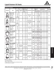
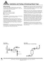
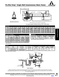
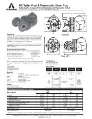
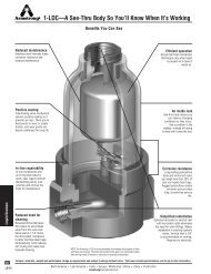
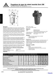
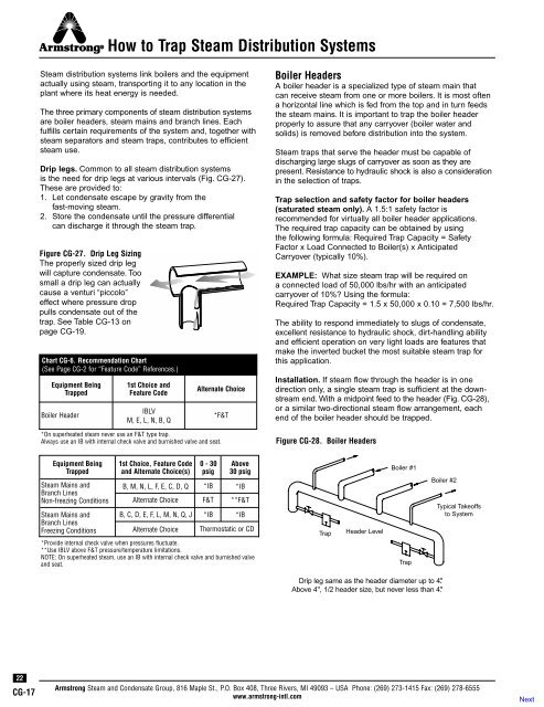
<strong>How</strong> <strong>to</strong> <strong>Trap</strong> <strong>Steam</strong> <strong>Distribution</strong> <strong>Systems</strong><strong>Steam</strong> distribution systems link boilers and the equipmentactually using steam, transporting it <strong>to</strong> any location in theplant where its heat energy is needed.The three primary components of steam distribution systemsare boiler headers, steam mains and branch lines. Eachfulfills certain requirements of the system and, <strong>to</strong>gether withsteam separa<strong>to</strong>rs and steam traps, contributes <strong>to</strong> efficientsteam use.Drip legs. Common <strong>to</strong> all steam distribution systemsis the need for drip legs at various intervals (Fig. CG-27).These are provided <strong>to</strong>:1. Let condensate escape by gravity from thefast-moving steam.2. S<strong>to</strong>re the condensate until the pressure differentialcan discharge it through the steam trap.Figure CG-27. Drip Leg SizingThe properly sized drip legwill capture condensate. Toosmall a drip leg can actuallycause a venturi “piccolo”effect where pressure droppulls condensate out of thetrap. See Table CG-13 onpage CG-19.Chart CG-6. Recommendation Chart(See Page CG-2 for “Feature Code” References.)Equipment Being<strong>Trap</strong>pedBoiler Header1st Choice andFeature CodeIBLVM, E, L, N, B, QAlternate Choice*F&T*On superheated steam never use an F&T type trap.Always use an IB with internal check valve and burnished valve and seat.Boiler HeadersA boiler header is a specialized type of steam main thatcan receive steam from one or more boilers. It is most oftena horizontal line which is fed from the <strong>to</strong>p and in turn feedsthe steam mains. It is important <strong>to</strong> trap the boiler headerproperly <strong>to</strong> assure that any carryover (boiler water andsolids) is removed before distribution in<strong>to</strong> the system.<strong>Steam</strong> traps that serve the header must be capable ofdischarging large slugs of carryover as soon as they arepresent. Resistance <strong>to</strong> hydraulic shock is also a considerationin the selection of traps.<strong>Trap</strong> selection and safety fac<strong>to</strong>r for boiler headers(saturated steam only). A 1.5:1 safety fac<strong>to</strong>r isrecommended for virtually all boiler header applications.The required trap capacity can be obtained by usingthe following formula: Required <strong>Trap</strong> Capacity = SafetyFac<strong>to</strong>r x Load Connected <strong>to</strong> Boiler(s) x AnticipatedCarryover (typically 10%).EXAMPLE: What size steam trap will be required ona connected load of 50,000 lbs/hr with an anticipatedcarryover of 10%? Using the formula:Required <strong>Trap</strong> Capacity = 1.5 x 50,000 x 0.10 = 7,500 lbs/hr.The ability <strong>to</strong> respond immediately <strong>to</strong> slugs of condensate,excellent resistance <strong>to</strong> hydraulic shock, dirt-handling abilityand efficient operation on very light loads are features thatmake the inverted bucket the most suitable steam trap forthis application.Installation. If steam flow through the header is in onedirection only, a single steam trap is sufficient at the downstreamend. With a midpoint feed <strong>to</strong> the header (Fig. CG-28),or a similar two-directional steam flow arrangement, eachend of the boiler header should be trapped.Figure CG-28. Boiler HeadersEquipment Being<strong>Trap</strong>ped<strong>Steam</strong> Mains andBranch LinesNon-freezing Conditions1st Choice, Feature Codeand Alternate Choice(s)0-30psigAbove30 psigB, M, N, L, F, E, C, D, Q *IB *IBAlternate Choice F&T **F&T<strong>Steam</strong> Mains and B, C, D, E, F, L, M, N, Q, J *IB *IBBranch LinesFreezing ConditionsAlternate Choice Thermostatic or CD*Provide internal check valve when pressures fluctuate.**Use IBLV above F&T pressure/temperature limitations.NOTE: On superheated steam, use an IB with internal check valve and burnished valveand seat.<strong>Trap</strong>Header LevelBoiler #1<strong>Trap</strong>Boiler #2Typical Takeoffs<strong>to</strong> SystemDrip leg same as the header diameter up <strong>to</strong> 4.''Above 4'', 1/2 header size, but never less than 4.''22CG-17<strong>Armstrong</strong> <strong>Steam</strong> and Condensate Group, 816 Maple St., P.O. Box 408, Three Rivers, MI 49093 – USA Phone: (269) 273-1415 Fax: (269) 278-6555www.armstrong-intl.com
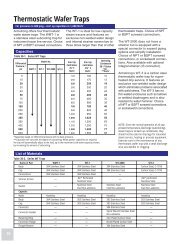
<strong>How</strong> <strong>to</strong> <strong>Trap</strong> <strong>Steam</strong> <strong>Distribution</strong> <strong>Systems</strong><strong>Steam</strong> MainsOne of the most common uses of steam traps is thetrapping of steam mains. These lines need <strong>to</strong> be kept free ofair and condensate in order <strong>to</strong> keep steam-using equipmen<strong>to</strong>perating properly. Inadequate trapping on steam mainsoften leads <strong>to</strong> water hammer and slugs of condensate thatcan damage control valves and other equipment.There are two methods used for the warm-up of steammains—supervised and au<strong>to</strong>matic. Supervised warm-upis widely used for initial heating of large-diameter and/orlong mains. The suggested method is for drip valves <strong>to</strong> beopened wide for free blow <strong>to</strong> the atmosphere before steamis admitted <strong>to</strong> the main. These drip valves are not closeduntil all or most of the warm-up condensate has beendischarged. Then the traps take over the job of removingcondensate that may form under operating conditions.Warm-up of principal piping in a power plant will followmuch the same procedure.Au<strong>to</strong>matic warm-up is when the boiler is fired, allowing themains and some or all equipment <strong>to</strong> come up <strong>to</strong> pressureand temperature without manual help or supervision.CAUTION: Regardless of warm-up method, allow sufficienttime during the warm-up cycle <strong>to</strong> minimize thermalstress and prevent any damage <strong>to</strong> the system.<strong>Trap</strong> selection and safety fac<strong>to</strong>r for steam mains(saturated steam only). Select trap <strong>to</strong> discharge condensateproduced by radiation losses at running load. Sizingfor start-up loads results in oversized traps, which may wearprematurely. Size drip legs <strong>to</strong> collect condensate duringlow-pressure, warm-up conditions. (See Table CG-13 onpage CG-19.) Condensate loads of insulated pipe can befound in Table CG-10. All figures in the table assume theinsulation <strong>to</strong> be 75% effective. For pressures or pipe sizesnot included in the table, use the following formula:C =A x U x (T 1 -T 2 )EHWhere:C = Condensate in lbs/hr-footA = External area of pipe in square feet(Table CG-10, Col. 2)U = Btu/sq ft/degree temperaturedifference/hr from Chart CG-7 (page CG-19)T 1 = <strong>Steam</strong> temperature in °FT 2 = Air temperature in °FE = 1 minus efficiency of insulation(Example: 75% efficient insulation:1 - .75 = .25 or E = .25)H = Latent heat of steam(See <strong>Steam</strong> Table on page CG-3)Table CG-10. Condensation in Insulated Pipes Carrying Saturated <strong>Steam</strong>in Quiet Air at 70°F (Insulation assumed <strong>to</strong> be 75% efficient.)Pressure, psigPipe Size(in)Table CG-11. The Warming-Up Load From 70°F, Schedule 40 Pipe<strong>Steam</strong> Pressure, psig 2 15 30 60 125 180 250Pipe Size(in)sq ft PerLineal ftwt of PipePer ft (lbs)15 30 60 125 180 250 450 600 900Pounds of Condensate Per Hour Per Lineal Foot1 .344 .05 .06 .07 .10 .12 .14 .186 .221 .2891-1/4 .434 .06 .07 .09 .12 .14 .17 .231 .273 .3591-1/2 .497 .07 .08 .10 .14 .16 .19 .261 .310 .4062 .622 .08 .10 .13 .17 .20 .23 .320 .379 .4982-1/2 .753 .10 .12 .15 .20 .24 .28 .384 .454 .5963 .916 .12 .14 .18 .24 .28 .33 .460 .546 .7143-1/2 1.047 .13 .16 .20 .27 .32 .38 .520 .617 .8074 1.178 .15 .18 .22 .30 .36 .43 .578 .686 .8975 1.456 .18 .22 .27 .37 .44 .51 .698 .826 1.0786 1.735 .20 .25 .32 .44 .51 .59 .809 .959 1.2538 2.260 .27 .32 .41 .55 .66 .76 1.051 1.244 1.62810 2.810 .32 .39 .51 .68 .80 .94 1.301 1.542 2.01912 3.340 .38 .46 .58 .80 .92 1.11 1.539 1.821 2.39314 3.670 .42 .51 .65 .87 1.03 1.21 1.688 1.999 2.62416 4.200 .47 .57 .74 .99 1.19 1.38 1.927 2.281 2.99718 4.710 .53 .64 .85 1.11 1.31 1.53 2.151 2.550 3.35120 5.250 .58 .71 .91 1.23 1.45 1.70 2.387 2.830 3.72524 6.280 .68 .84 1.09 1.45 1.71 2.03 2.833 3.364 4.434Pounds of Water Per Lineal Foot1 1.69 .030 .037 .043 .051 .063 .071 .0791-1/4 2.27 .040 .050 .057 .068 .085 .095 .1061-1/2 2.72 .048 .059 .069 .082 .101 .114 .1272 3.65 .065 .080 .092 .110 .136 .153 .1712-1/2 5.79 .104 .126 .146 .174 .215 .262 .2713 7.57 .133 .165 .190 .227 .282 .316 .3543-1/2 9.11 .162 .198 .229 .273 .339 .381 .4264 10.79 .190 .234 .271 .323 .400 .451 .5055 14.62 .258 .352 .406 .439 .544 .612 .6846 18.97 .335 .413 .476 .569 .705 .795 .8828 28.55 .504 .620 .720 .860 1.060 1.190 1.34010 40.48 .714 .880 1.020 1.210 1.500 1.690 1.89012 53.60 .945 1.170 1.350 1.610 2.000 2.240 2.51014 63.00 1.110 1.370 1.580 1.890 2.340 2.640 2.94016 83.00 1.460 1.810 2.080 2.490 3.080 3.470 3.88018 105.00 1.850 2.280 2.630 3.150 3.900 4.400 4.90020 123.00 2.170 2.680 3.080 3.690 4.570 5.150 5.75024 171.00 3.020 3.720 4.290 5.130 6.350 7.150 8.000Table CG-12. Pipe Weights Per Foot in PoundsPipe Size (in) Schedule 40 Schedule 80 Schedule 160 XX Strong1 1.69 2.17 2.85 3.661-1/4 2.27 3.00 3.76 5.211-1/2 2.72 3.63 4.86 6.412 3.65 5.02 7.45 9.032-1/2 5.79 7.66 10.01 13.693 7.57 10.25 14.32 18.583-1/2 9.11 12.51 — 22.854 10.79 14.98 22.60 27.545 14.62 20.78 32.96 38.556 18.97 28.57 45.30 53.168 28.55 43.39 74.70 72.4210 40.48 54.74 116.00 —12 53.60 88.60 161.00 —14 63.00 107.00 190.00 —16 83.00 137.00 245.00 —18 105.00 171.00 309.00 —20 123.00 209.00 379.00 —24 171.00 297.00 542.00 —<strong>Armstrong</strong> <strong>Steam</strong> and Condensate Group, 816 Maple St., P.O. Box 408, Three Rivers, MI 49093 – USA Phone: (269) 273-1415 Fax: (269) 278-6555www.armstrong-intl.com23CG-18
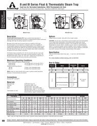
<strong>How</strong> <strong>to</strong> <strong>Trap</strong> <strong>Steam</strong> <strong>Distribution</strong> <strong>Systems</strong>For traps installed between the boiler and the end of the steammain, apply a 2:1 safety fac<strong>to</strong>r. Apply a 3:1 safety fac<strong>to</strong>r fortraps installed at the end of the main or ahead of reducingand shu<strong>to</strong>ff valves that are closed part of the time.The inverted bucket trap is recommended because it canhandle dirt and slugs of condensate and resists hydraulicshock. In addition, should an inverted bucket fail, it usuallydoes so in the open position.Installation. Both methods of warm-up use drip legs andtraps at all low spots or natural drainage points such as:Ahead of risersEnd of mainsAhead of expansion joints or bendsAhead of valves or regula<strong>to</strong>rsChart CG-7. Btu Heat Loss CurvesBTU PER SQ FT PER HOUR PER °F TEMPERATURE DIFFERENCETEMPERATURE DIFFERENCE150° 160° 180° 200° 240° 300° 400° 500° 700° 900° 1050°1110987654.54.03.53.33.02.82.62.52.42.32.22.15PSIG5.31"2"3"5"6"10"10.315.3FLAT SURFACES25.350.375.3100.3150.3250.3450.3600.3900.31500.32400.3PRESSURE IN LBS PER SQUARE INCH1110987654.54.03.53.33.02.82.62.52.42.32.22.152.10Install drip legs and drain traps even where there are nonatural drainage points (See Figs. CG-29, CG-30 and CG-31).These should normally be installed at intervals of about 300'and never longer than 500'.On a supervised warm-up, make drip leg length at least1-1/2 times the diameter of the main, but never less than10". Make drip legs on au<strong>to</strong>matic warm-ups a minimum of28" in length. For both methods, it is a good practice <strong>to</strong> usea drip leg the same diameter as the main up <strong>to</strong> 4" pipe sizeand at least 1/2 of the diameter of the main above that, butnever less than 4". See Table CG-13.Table CG-13. Recommended <strong>Steam</strong> Main and Branch Line Drip Leg SizingM<strong>Steam</strong> MainSize (in)Chart CG-8. Recommendation Chart(See Page CG-2 for “Feature Code” References.)Equipment Being<strong>Trap</strong>ped<strong>Steam</strong> Separa<strong>to</strong>r1st Choice andFeature CodeIBLVB, M, L, E, F, N, Q*DC is 1st choice where steam quality is 90% or less.DDrip LegDiameter (in)Drip Leg Length Min. (in)SupervisedWarm-UpAu<strong>to</strong>maticWarm-Up1/2 1/2 10 283/4 3/4 10 281 1 10 282 2 10 283 3 10 284 4 10 286 4 10 288 4 12 2810 6 15 2812 6 18 2814 8 21 2816 8 24 2818 10 27 2820 10 30 3024 12 36 36HAlternate Choice*DC<strong>Steam</strong> MainsMMDDrip leg sameas the headerdiameter up <strong>to</strong>4''. Above 4'',1/2 header size,but never lessthan 4''.HH24CG-19Figure CG-29.<strong>Trap</strong> draining strainer ahead of PRV.Figure CG-30.<strong>Trap</strong> draining drip leg on main.Figure CG-31.<strong>Trap</strong> draining drip leg at riser. Distance“H” in inches ÷ 28 = psi static head forforcing water through the trap.<strong>Armstrong</strong> <strong>Steam</strong> and Condensate Group, 816 Maple St., P.O. Box 408, Three Rivers, MI 49093 – USA Phone: (269) 273-1415 Fax: (269) 278-6555www.armstrong-intl.com
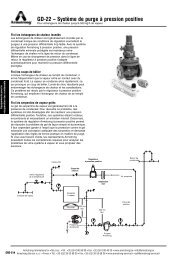
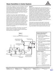
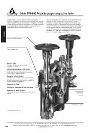
<strong>How</strong> <strong>to</strong> <strong>Trap</strong> <strong>Steam</strong> <strong>Distribution</strong> <strong>Systems</strong>Branch LinesBranch lines are take-offs from the steam mains supplyingspecific pieces of steam-using equipment. The entire systemmust be designed and hooked up <strong>to</strong> prevent accumulation ofcondensate at any point.<strong>Trap</strong> selection and safety fac<strong>to</strong>r for branch lines. Theformula for computing condensate load is the same asthat used for steam mains. Branch lines also have a recommendedsafety fac<strong>to</strong>r of 3:1.Installation. Recommended piping from the main <strong>to</strong> thecontrol is shown in Fig. CG-32 for runouts under 10' andFig. CG-33 for runouts over 10'. See Fig. CG-34 for pipingwhen control valve must be below the main.Install a full pipe-size strainer ahead of each control valveas well as ahead of the PRV, if used. Provide blowdownvalves, preferably with IB traps. A few days after startingthe system, examine the strainer screens <strong>to</strong> see if cleaningis necessary.Separa<strong>to</strong>rs<strong>Steam</strong> separa<strong>to</strong>rs are designed <strong>to</strong> remove any condensatethat forms within steam distribution systems. They are mos<strong>to</strong>ften used ahead of equipment where especially dry steamis essential. They are also common on secondary steamlines, which by their very nature have a large percentage ofentrained condensate.Figure CG-32. Piping for runout less than 10 ft. No traprequired unless pitch back <strong>to</strong> supply header is less than1/2'' per ft.More than10'Branch Lines10' or LessPitch 1/2'' per 1 ftRunout OversizedOne Pipe Sizeor MoreImportant fac<strong>to</strong>rs in trap selection for separa<strong>to</strong>rs are theability <strong>to</strong> handle slugs of condensate, provide good resistance<strong>to</strong> hydraulic shock and operate on light loads.<strong>Trap</strong> selection and safety fac<strong>to</strong>rs for separa<strong>to</strong>rs. Applya 3:1 safety fac<strong>to</strong>r in all cases, even though different typesof traps are recommended, depending on condensate andpressure levels.Use the following formula <strong>to</strong> obtain the required trap capacity:Required trap capacity in lbs/hr = safety fac<strong>to</strong>r x steam flowrate in lbs/hr x anticipated percent of condensate (typically10% <strong>to</strong> 20%).EXAMPLE: What size steam trap will be required on a flowrate of 10,000 lbs/hr? Using the formula:Required trap capacity =3 x 10,000 x 0.10 = 3,000 lbs/hr.The inverted bucket trap with large vent is recommended forsepara<strong>to</strong>rs. When dirt and hydraulic shock are not significantproblems, an F&T type trap is an acceptable alternative.An au<strong>to</strong>matic differential condensate controller may be preferredin many cases. It combines the best features of bothof the above and is recommended for large condensateloads that exceed the separating capability of the separa<strong>to</strong>r.InstallationConnect traps <strong>to</strong> the separa<strong>to</strong>r drain line 10" <strong>to</strong> 12" belowthe separa<strong>to</strong>r with the drain pipe running the full size of thedrain connection down <strong>to</strong> the trap take-off (Fig. CG-35). Thedrain pipe and dirt pocket should be the same size as thedrain connection.<strong>Steam</strong> Separa<strong>to</strong>r<strong>Steam</strong>Separa<strong>to</strong>rPitch Down 1/2''per 10 ftShu<strong>to</strong>ff Valve10''-12''Figure CG-33. Piping for runout greaterthan 10'. Drip leg and trap requiredahead of control valve. Strainer aheadof control valve can serve as dripleg if blowdown connection runs <strong>to</strong>an inverted bucket trap. This will alsominimize the strainer cleaning problem.<strong>Trap</strong> should be equipped with an internalcheck valve or a swing check installedahead of the trap.Figure CG-34. Regardless of the lengthof the runout, a drip leg and trap arerequired ahead of the control valvelocated below steam supply. If coil isabove control valve, a trap should alsobe installed at downstream side ofcontrol valve.Figure CG-35. Drain downstream sideof separa<strong>to</strong>r. Full-size drip leg and dirtpocket are required <strong>to</strong> ensure positiveand fast flow of condensate <strong>to</strong> the trap.<strong>Armstrong</strong> <strong>Steam</strong> and Condensate Group, 816 Maple St., P.O. Box 408, Three Rivers, MI 49093 – USA Phone: (269) 273-1415 Fax: (269) 278-6555www.armstrong-intl.com6''IBLV orDC25CG-20
<strong>How</strong> <strong>to</strong> <strong>Trap</strong> <strong>Steam</strong> Tracer Lines<strong>Steam</strong> tracer lines are designed <strong>to</strong> maintain the fluid in aprimary pipe at a certain uniform temperature. In mostcases, these tracer lines are used outdoors, which makesambient weather conditions a critical consideration.The primary purpose of steam traps on tracer lines is <strong>to</strong>retain the steam until its latent heat is fully utilized and thendischarge the condensate and non-condensable gases. Asis true with any piece of heat transfer equipment, each tracerline should have its own trap. Even though multiple tracerlines may be installed on the same primary fluid line, unittrapping is required <strong>to</strong> prevent short circuiting. See page CG-15.In selecting and sizing steam traps, it’s important <strong>to</strong> considertheir compatibility with the objectives of the system, astraps must:1. Conserve energy by operating reliably over a long periodof time.2. Provide abrupt periodic discharge in order <strong>to</strong> purge thecondensate and air from the line.3. Operate under light load conditions.4. Resist damage from freezing if the steam is shut off.<strong>Trap</strong> Selection for <strong>Steam</strong> Tracer Lines.The condensate load <strong>to</strong> be handled on a steam tracer linecan be determined from the heat loss from the product pipeby using this formula:Q = L x U x ∆T x ES x HWhere:Q = Condensate load, lbs/hrL = Length of product pipe between tracerline traps in ftU = Heat transfer fac<strong>to</strong>r in Btu/sq ft/°F/hr(from Chart CG-7, page CG-19)∆T = Temperature differential in °FE = 1 minus efficiency of insulation(example: 75% efficient insulation or1 - .75 = .25 or E = .25)S = Lineal feet of pipe line per sq ft of surface(from Table CG-29, page CG-53)H = Latent heat of steam in Btu/lb(from <strong>Steam</strong> Table, page CG-3)The cost of steam makes wasteful tracer lines an exorbitan<strong>to</strong>verhead no industry can afford.Typical Tracer InstallationFigure CG-36.Figure CG-37.CheckValveFreeze-Protection Drain26CG-21Chart CG-9. Recommendation Chart(See Page CG-2 for “Feature Code” References.)Equipment Being<strong>Trap</strong>pedTracer Lines1st Choice andFeature Code*IBA, B, C, L, J, N, I, KAlternate ChoiceThermostatic or CD*Select a 5/64" steam trap orifice <strong>to</strong> conserve energy and avoid plugging with dirtand scale.Table CG-14. Pipe Size Conversion Table (Divide lineal feet of pipe byfac<strong>to</strong>r given for size and type of pipe <strong>to</strong> get square feet of surface.)Pipe Size (in)Iron PipeCopper orBrass Pipe1/2 4.55 7.633/4 3.64 5.091 2.90 3.821-1/4 2.30 3.051-1/2 2.01 2.552 1.61 1.912-1/2 1.33 1.523 1.09 1.274 .848 .954<strong>Armstrong</strong> <strong>Steam</strong> and Condensate Group, 816 Maple St., P.O. Box 408, Three Rivers, MI 49093 – USA Phone: (269) 273-1415 Fax: (269) 278-6555www.armstrong-intl.com
<strong>How</strong> <strong>to</strong> <strong>Trap</strong> <strong>Steam</strong> Tracer LinesEXAMPLE: Three tracer lines at 100 psig steam pressureare used on a 20" diameter, 100' long insulated pipe <strong>to</strong>maintain a temperature of 190°F with an outdoor designtemperature of -10°F. Assume further that the pipe insulationis 75% efficient. What is the condensate load?Using the formula:Q =100 ft x 2.44 Btu/sq ft -°F - hr x 200°F x .250.191 lin ft/sq ft x 800 Btu/lbNow divide by three in order <strong>to</strong> get the load pertracer line—24 lbs/hr.= 72 lbs/hrOn most tracer line applications, the flow <strong>to</strong> the steam trapis surprisingly low; therefore, the smallest trap is normallyadequate. Based on its ability <strong>to</strong> conserve energy by operatingreliably over a long period of time, handle light loads,resist freezing and purge the system, an inverted buckettrap is recommended for tracer line service.Safety fac<strong>to</strong>r. Use a 2:1 safety fac<strong>to</strong>r whether exposure<strong>to</strong> ambient weather conditions is involved or not. Do no<strong>to</strong>versize steam traps or tracer lines. Select a 5/64" steamtrap orifice <strong>to</strong> conserve energy and avoid pluggingwith dirt and scale.InstallationInstall distribution or supply lines at a height above theproduct lines requiring steam tracing. For the efficientdrainage of condensate and purging of non-condensables,pitch tracer lines for gravity drainage and trap all low spots.This will also help avoid tracer line freezing. (See Figs.CG-36, CG-37 and CG-38.)To conserve energy, return condensate <strong>to</strong> the boiler.Use vacuum breakers immediately ahead of the traps<strong>to</strong> ensure drainage on shutdown on gravity drain systems.Freeze-protection drains on trap discharge headers aresuggested where freezing conditions prevail.Figure CG-38. Typical Tracer InstallationChart CG-10. Btu Heat Loss CurvesUnit heat loss per sq ft of surface of uninsulated pipe ofvarious diameters (also flat surface) in quiet air at 75°F forvarious saturated steam pressures or temperature differences.TEMPERATURE DIFFERENCE150° 160° 180° 200° 240° 300° 400° 500° 700° 900° 1050°VacuumBreakerFreeze-Protection DrainBTU PER SQ FT PER HOUR PER °F TEMPERATURE DIFFERENCE1110987654.54.03.53.33.02.82.62.52.42.32.21"2"3"5"6"10"FLAT SURFACES1110987654.54.03.53.33.02.82.62.52.42.32.22.152.15PSIG5.310.315.325.350.375.3100.3150.3250.3450.3600.3900.31500.32400.32.10PRESSURE IN LBS PER SQUARE INCH<strong>Armstrong</strong> <strong>Steam</strong> and Condensate Group, 816 Maple St., P.O. Box 408, Three Rivers, MI 49093 – USA Phone: (269) 273-1415 Fax: (269) 278-6555www.armstrong-intl.com27CG-22
<strong>How</strong> <strong>to</strong> <strong>Trap</strong> Superheated <strong>Steam</strong> LinesAt first glance, this may seem confusing due <strong>to</strong> the ideathat superheated steam produces no condensate; therefore,the steam lines carrying superheated steam should not haveany condensate in them. This is true once the system is up<strong>to</strong> temperature and pressure, but condensate removal isnecessary up <strong>to</strong> this point. This section will explain whatsuperheated steam is and the applications for its use.The specific heat of any substance (using Btu standards)is the quantity of heat required <strong>to</strong> raise the temperature of1 pound by 1 degree F. With this definition, the specific hea<strong>to</strong>f water is 1, and the specific heat of superheated steamvaries according <strong>to</strong> temperature and pressure. Specific heatdecreases as the temperature rises but increases as thepressure goes up.Superheated steam is cus<strong>to</strong>marily made by the addition ofan extra set of coils inside the boiler or in the exhaust areaof the boiler so as <strong>to</strong> use the “waste” heat from the boiler.Or, by the addition of a superheat chamber somewhere afterthe boiler, attached <strong>to</strong> the steam main. A schematic diagramof a steam genera<strong>to</strong>r with a superheated section of coil isshown below.Properties of Superheated <strong>Steam</strong>Superheated steam has several properties that make itunsuitable as a heat energy exchange medium yet idealfor work and mass transfer. Unlike saturated steam, thepressure and temperature of superheated steam are independent.As superheat is formed at the same pressure asthe saturated steam, the temperature and volume increase.In high heat release boilers with relatively small drums,separation of steam from water is extremely difficult.The combination of the small volume of water in the drumsand rapid load swings produces severe shrink and swellconditions in the drum, which promotes water carryover.Figure CG-39. <strong>Steam</strong> Genera<strong>to</strong>rPreheatedAirStackGases OutletAirInletThis water can be removed with separa<strong>to</strong>rs and trapsin the steam outlets, but they are not 100% efficient. Inapplications where dry steam is a necessity, additionalsuperheating coils are placed in the boiler furnace asconvection passes. More heat is added <strong>to</strong> the steam <strong>to</strong>vaporize the water carryover, which adds a small amoun<strong>to</strong>f superheat <strong>to</strong> guarantee absolutely dry steam.Because superheated steam can give up so little heatbefore it converts back <strong>to</strong> saturated steam, it is not a goodheat-transfer medium. Some processes, such as powerplants, require a dry heat in order <strong>to</strong> do work. Whateverthe type of power unit, superheat helps reduce the amoun<strong>to</strong>f condensation when starting from cold. Superheat alsoincreases the power output by delaying condensation duringthe expansion stages in the equipment. Having drier steamat the exhaust end will increase the life of turbine blades.Superheated steam can lose heat without condensingwhereas saturated steam cannot. Therefore, superheatedsteam can be transported through very long steam lineswithout losing sufficient heat <strong>to</strong> condense. This permits thedelivery of dry steam throughout the entire steam system.Why <strong>Trap</strong> Superheated <strong>Systems</strong>?The primary reason for traps on superheat systems is thestart-up load. It can be heavy because of the large sizeof the mains. On start-up, manual valves will most likely beused since time is available <strong>to</strong> open and <strong>to</strong> close the valves.This is known as supervised start-up. A second reason forsteam traps is <strong>to</strong> handle emergencies such as superheaterloss or by-pass, which might require operation on saturatedsteam. In these unscheduled events, there is no timeavailable for manually opening valves; therefore, steamtraps are a necessity.These are the situations for which proper trap sizing is amust. Condensate must be removed as it forms in any steamsystem <strong>to</strong> keep efficiency high and <strong>to</strong> minimize damagingwater hammer and erosion.Superheated <strong>Steam</strong>(High Pressure)WarmAirHot WaterTurbineGenera<strong>to</strong>rVapor<strong>Steam</strong>(Low Pressure)FuelSuperheaterLow-TemperatureWater(High Pressure)CondenserPumpCool WaterPump28CG-23Cool Water(From Tower orLake/River)<strong>Armstrong</strong> <strong>Steam</strong> and Condensate Group, 816 Maple St., P.O. Box 408, Three Rivers, MI 49093 – USA Phone: (269) 273-1415 Fax: (269) 278-6555www.armstrong-intl.com
<strong>How</strong> <strong>to</strong> <strong>Trap</strong> Superheated <strong>Steam</strong> LinesSizing Superheat Loads <strong>to</strong> <strong>Trap</strong>sThe condensate load <strong>to</strong> a trap used on superheat will varywidely from severe start-up loads <strong>to</strong> virtually no load duringoperation. Consequently, this is a demanding application forany steam trap.During start-up, very large lines are being filled with steamfrom cold conditions. At this time, only saturated steam atlow pressure is in the lines until the line temperature canbe increased. This is done slowly over a long period so thelines are not stressed. Large condensate flow combined withlow pressure is the start-up condition that requires the useof large capacity traps. These oversized traps are thenrequired <strong>to</strong> operate at very high pressures with very lowcapacity requirements during normal superheat operation.Typical start-up loads can be roughly calculated as follows:Using:C0.114 Wp (t2-t1)=HWhere:C = Amount of condensate in poundsWp = Total weight of pipe (from Table CG-12 onpage CG-18)H = Total heat of X pressure minus Sensible heat of YPressure (Latent heat of steam. For long warm-uptimes, use the <strong>to</strong>tal heat of saturated steam at thesuperheat steam supply pressure (X) minus thesensible heat of saturated steam at the averagepressure (Y) during the warm-up time involved.)0.114 = Specific heat of steel pipe in btu/lb °FEXAMPLE:Assuming a 100°F/hr (37°C/hr) heat-up14'' (35 cm) diameter Schedule 80 lineSupply superheated steam at 1200 psig 1070°F (85 bar, 577°C)Ambient temperature is 70°F (21°C)200 feet (61 m) of run between trapsFor the first two hours:W = (200 ft) (107 lb/ft) = 21,400 lb (9727 kg)t(2) - t(1) = 270 - 70 = 200°F (93°C)H = 1184.8 btu/lb - 196.27 btu/lb = 988.5 btu/lb = (474 kJ)C =(0.114 btu/lb °F) (21,400 lb) (200°F)988.5 btu/lb= 493 lb (224 kg)For the second two hours:The only thing that changes is the sensible heat of thesaturated steam at average pressure during the time involved.Table CG-15. Time Period TableTime PeriodAveragePressurepsig (bar)Temperature atEnd of Time Period°F (°C)14" LineCondensation Ratelb/hr (kg/hr)1 st 2 hours 5 (.35) 270 (132) 247 (112)2 nd 2 hours 140 (9.8) 470 (243) 286 (130)3 rd 2 hours 700 (49) 670 (354) 352 (160)4 th 2 hours 1200 (85) 870 (465) 288 (131)5 th 2 hours 1200 (85) 1070 (577) 260 (118)NOTE: For the average pressure of 1,200 psig (85 bar), assume H <strong>to</strong> be the latent hea<strong>to</strong>f 1,200 psig (85 bar) steam plus superheat at temperature at the end of the period.To ensure the condensate is removed efficiently, properdrip leg sizing and piping recommendations should alsobe followed when installing traps on superheat systems.The Table CG-13 on page CG-19 lists the proper drip legsize for given pipe sizes.The question arises whether insulation should be usedon the drip leg, piping leading <strong>to</strong> the trap, and the trap.The answer is no; unless it is manda<strong>to</strong>ry for safety reasons,this section of the steam system should not be insulated.This ensures that some condensate is continuously beingformed ahead of the trap and going <strong>to</strong> it, thus prolongingthe trap’s life.Types of Superheat <strong>Trap</strong>sBimetallicA bimetallic trap is set <strong>to</strong> not open until condensate has cooled<strong>to</strong> a temperature below saturation. For the existing pressure,it will remain closed whenever steam of any temperature isin the trap. As the steam temperature rises, the pull of thebimetallic element becomes greater, providing a greater sealingforce on the valve. Superheated steam tends <strong>to</strong> seal thevalve better. The bimetallic trap also has the ability <strong>to</strong> handlelarge start-up loads. For these reasons, this trap is a goodchoice for superheat.During superheat operation, the condensate in the trapmust cool <strong>to</strong> a temperature below the saturation temperaturebefore the trap can open. Condensate may back up in<strong>to</strong> theline and cause damage <strong>to</strong> the lines, valves and equipment ifdrip leg size and length before the trap are insufficient.Inverted BucketA water seal prevents steam from getting <strong>to</strong> the valve,promoting no live steam loss and long life. The valve atthe <strong>to</strong>p makes it impervious <strong>to</strong> dirt and permits removal ofair. Large start-up loads can be handled, and the trap canstill accommodate small running loads. There are problemsassociated with its application on superheat, mostly associatedwith the necessity of maintaining its water seal or “prime.”Proper piping is necessary <strong>to</strong> maintain a prime in the IB.C =(0.114 btu/lb °F) (21,400 lb) (200°F)851.1 btu/lb= 573 lb (260 kg)For proper inverted bucket piping on superheat, refer <strong>to</strong>Figure CG-31 on page CG-19. When sizing a superheattrap, size for start-up load with no safety fac<strong>to</strong>r. Bodymaterials should be selected on the basis of maximumpressure and temperature, including superheat.<strong>Armstrong</strong> <strong>Steam</strong> and Condensate Group, 816 Maple St., P.O. Box 408, Three Rivers, MI 49093 – USA Phone: (269) 273-1415 Fax: (269) 278-6555www.armstrong-intl.com29CG-24
<strong>How</strong> <strong>to</strong> <strong>Trap</strong> Space Heating EquipmentSpace heating equipment such as unit heaters, air handlingunits, finned radiation and pipe coils is found in virtually allindustries. This type of equipment is quite basic and shouldrequire very little routine maintenance. Consequently, thesteam traps are usually neglected for long periods of time.One of the problems resulting from such neglect is residualcondensate in the heating coil, which can cause damagedue <strong>to</strong> freezing, corrosion and water hammer.<strong>Trap</strong> Selection and Safety Fac<strong>to</strong>rsDifferent application requirements involving constant orvariable steam pressure determine which type and size oftrap should be used. There are two standard methods forsizing traps for coils.1. Constant <strong>Steam</strong> Pressure.INVERTED BUCKET TRAPS AND F&T TRAPS—Use a3:1 safety fac<strong>to</strong>r at operating pressure differentials.2. Modulating <strong>Steam</strong> Pressure.F&T TRAPS AND INVERTED BUCKET TRAPSWITH THERMIC BUCKETS■ 0-15 psig steam—2:1 safety fac<strong>to</strong>r at 1/2 psi pressuredifferential■ 16-30 psig steam—2:1 at 2 psi pressure differential■ Above 30 psig steam—3:1 at 1/2 of maximum pressuredifferential across the trap.INVERTED BUCKET TRAPS WITHOUT THERMIC BUCKETSAbove 30 psig steam pressure only—3:1 at 1/2 of maximumpressure differential across the trap.<strong>Trap</strong> Selection for Unit Heatersand Air Handling UnitsYou may use three methods <strong>to</strong> compute the amount ofcondensate <strong>to</strong> be handled. Known operating conditionswill determine which method <strong>to</strong> use.1. Btu method. The standard rating for unit heaters andother air coils is Btu output with 2 psig steam pressure inthe heater and entering air temperature of 60°F. To convertfrom standard <strong>to</strong> actual rating, use the conversion fac<strong>to</strong>rsin Table CG-16 (page CG-27). Once the actual operatingconditions are known, multiply the condensate load bythe proper safety fac<strong>to</strong>r.2. CFM and air temperature rise method. If you knowonly CFM capacity of fan and air temperature rise,find the actual Btu output by using this simple formula:Btu/hr = CFM x 1.08 x temperature rise in °F.EXAMPLE: What size trap will drain a 3,500 CFM heaterthat produces an 80°F temperature rise? <strong>Steam</strong> pressureis constant at 60 psig.Using the formula:3,500 x 1.08 x 80 = 302,400 Btu/hr.Now divide 302,400 Btu/hr by 904.5 Btu (from the <strong>Steam</strong>Tables) <strong>to</strong> obtain 334 lbs/hr and then multiply by the recommendedsafety fac<strong>to</strong>r 3. The application needs a trap with a1,002 lbs/hr capacity.Derive the 1.08 fac<strong>to</strong>r in the above formula as follows:1 CFM x 60 = 60 CFH60 CFH x .075 lbs of air/cu ft = 4.5 lbs of air/hr4.5 x 0.24 Btu/lb -°F (specific heat of air) = 1.08 Btu/hr °F - CFM.3. Condensate method.Once you determine Btu output:a. Divide Btu output by latent heat of steam at steampressure used. See Column 2 of Table CG-16(page CG-27) or the <strong>Steam</strong> Table (page CG-3). This willgive the actual weight of steam condensed. For a closeapproximation, a rule of thumb could be applied inwhich the Btu output is simply divided by 1,000.b. Multiply the actual weight of steam condensing bythe safety fac<strong>to</strong>r <strong>to</strong> get the continuous trap dischargecapacity required.Chart CG-11. Multipliers for Sizing <strong>Trap</strong>s for Multiple CoilsMULTIPLIER20171512108765STEAM PRESSURE PSIG2 5 10 15 25 50 100 125 180 250 201715FORCED AIR CIRCULATIONDRYING WET CLAYDAMP ATMOSPHERESORDINARY SPACE HEATING442 5 10 15 25 50 100 125 180 25012108765MULTIPLIER30CG-25Chart CG-12. Recommendation Chart(See Page CG-2 for “Feature Code” References.)Equipment Being<strong>Trap</strong>pedUnit HeatersAir Handling UnitsFinned Radiation &Pipe Coils1st Choice andConstant Pressure1st Choice andVariable PressureFeature Code 0-30 psig Above 30 psig Feature Code 0-30 psig Above 30 psigB, C, E, K, N IBLV IBLV B, C, G, H, L F&T *F&TAlternate Choice F&T *F&T Alternate Choice IBLV IBLVB, C, E, K, N, O IBLV IBLV B, C, G, H, L F&T *F&TAlternate Choice F&T *F&T Alternate Choice IBT IBLVB, C, E, K, N IBLV IBLV B, C, G, H, L F&T F&TAlternate Choice Thermostatic Thermostatic Alternate Choice IBLV IBLV*Use IBLV above F&T pressure/temperature limitations.PLEASE NOTE: 1. Provide vacuum breaker wherever subatmospheric pressures occur.2. Do not use F&T traps on superheated steam.<strong>Armstrong</strong> <strong>Steam</strong> and Condensate Group, 816 Maple St., P.O. Box 408, Three Rivers, MI 49093 – USA Phone: (269) 273-1415 Fax: (269) 278-6555www.armstrong-intl.com
<strong>How</strong> <strong>to</strong> <strong>Trap</strong> Space Heating EquipmentTable CG-16. A Table of Constants for determining the Btu output of a unit heater with conditions other than standard — standard being with 2 lbssteam pressure at 60°F entering air temperature. To apply, multiply the standard Btu capacity rating of heater by the indicated constant. (Reprinted fromASHRAE Guide by special permission.)<strong>Steam</strong> Pressurelbs Persq inLatent Hea<strong>to</strong>f <strong>Steam</strong>Entering Air Temperature °F-10 0 10 20 30 40 50 60 70 80 90 1002 966.3 — — — — — 1.155 1.078 1.000 0.926 0.853 0.782 0.7135 960.7 1.640 1.550 1.456 1.370 1.289 1.206 1.127 1.050 0.974 0.901 0.829 0.76010 952.4 1.730 1.639 1.545 1.460 1.375 1.290 1.211 1.131 1.056 0.982 0.908 0.83815 945.5 1.799 1.708 1.614 1.525 1.441 1.335 1.275 1.194 1.117 1.043 0.970 0.89720 939.3 1.861 1.769 1.675 1.584 1.498 1.416 1.333 1.251 1.174 1.097 1.024 0.95230 928.5 1.966 1.871 1.775 1.684 1.597 1.509 1.429 1.346 1.266 1.190 1.115 1.04240 919.3 2.058 1.959 1.862 1.771 1.683 1.596 1.511 1.430 1.349 1.270 1.194 1.11950 911.2 2.134 2.035 1.936 1.845 1.755 1.666 1.582 1.498 1.416 1.338 1.262 1.18760 903.9 2.196 2.094 1.997 1.902 1.811 1.725 1.640 1.555 1.472 1.393 1.314 1.23970 897.3 2.256 2.157 2.057 1.961 1.872 1.782 1.696 1.610 1.527 1.447 1.368 1.29375 893.8 2.283 2.183 2.085 1.990 1.896 1.808 1.721 1.635 1.552 1.472 1.392 1.31680 891.1 2.312 2.211 2.112 2.015 1.925 1.836 1.748 1.660 1.577 1.497 1.418 1.34290 885.4 2.361 2.258 2.159 2.063 1.968 1.880 1.792 1.705 1.621 1.541 1.461 1.383100 880.0 2.409 2.307 2.204 2.108 2.015 1.927 1.836 1.749 1.663 1.581 1.502 1.424Table CG-17. Finned Radiation Conversion Fac<strong>to</strong>rs for steam pressuresand air temperatures other than 65°F air and 215°F steam.<strong>Steam</strong>Pressure(psig)<strong>Steam</strong> Temp.(°F)Entering Air Temperature °F45 55 65 70 75 80 90.9 215.0 1.22 1.11 1.00 .95 .90 .84 .755 227.1 1.34 1.22 1.11 1.05 1.00 .95 .8110 239.4 1.45 1.33 1.22 1.17 1.11 1.05 .9115 249.8 1.55 1.43 1.31 1.26 1.20 1.14 1.0030 274.0 1.78 1.66 1.54 1.48 1.42 1.37 1.2160 307.3 2.10 2.00 1.87 1.81 1.75 1.69 1.51100 337.9 2.43 2.31 2.18 2.11 2.05 2.00 1.81125 352.9 2.59 2.47 2.33 2.27 2.21 2.16 1.96175 377.4 2.86 2.74 2.60 2.54 2.47 2.41 2.21Table CG-18. Condensing Rates in Bare Pipe Carrying Saturated <strong>Steam</strong><strong>Steam</strong> Pressure (psig)Temp. Rise From 70°Pounds of Condensate Per hr Per Lineal ftPipe Size(in)sq ft PerLineal ft15180°30204°60237°125283°180310°250336°1/2 .220 .13 .15 .19 .26 .30 .353/4 .275 .15 .19 .24 .33 .38 .451 .344 .19 .23 .28 .39 .46 .541-1/4 .434 .23 .28 .36 .49 .57 .671-1/2 .497 .26 .32 .41 .55 .65 .762 .622 .33 .40 .50 .68 .80 .932-1/2 .753 .39 .47 .59 .81 .95 1.113 .916 .46 .56 .70 .96 1.13 1.313-1/2 1.047 .52 .63 .80 1.08 1.27 1.504 1.178 .58 .70 .89 1.21 1.43 1.72Table CG-19. Finned Radiation Condensing Rates with 65°F air and 215°Fsteam (for trap selection purposes only).Steel Pipe,Steel FinsPaintedBlackCopper PipeAluminumFinsUnpaintedPipeSize (in)1-1/4Fin Size(in)Fins Per<strong>Inc</strong>h1-1/4 3-1/4 3 <strong>to</strong> 421-1/41-1/44-1/44-1/43-1/44-1/43<strong>to</strong>42<strong>to</strong>345No.ofPipesHigh on6'' CentersCondensatelbs/hr PerFoot of Pipe1 1.12 2.03 2.61 1.62 2.43 3.11 1.52 2.43 3.11 1.62 2.23 2.81 2.22 3.03 3.632CG-27<strong>Armstrong</strong> <strong>Steam</strong> and Condensate Group, 816 Maple St., P.O. Box 408, Three Rivers, MI 49093 – USA Phone: (269) 273-1415 Fax: (269) 278-6555www.armstrong-intl.com
<strong>How</strong> To <strong>Trap</strong> Process Air HeatersProcess air heaters are used for drying paper, lumber, milk,starch and other products as well as preheating combustionair for boilers.Common examples of this type of equipment are processdryers, tunnel dryers, and combustion air preheaters.Compared with air heaters for space heating, process airheaters operate at very high temperature, 500°F not beinguncommon. These extremely high-temperature applicationsrequire high pressure (and occasionally superheated) steam.<strong>Trap</strong> Selection and Safety Fac<strong>to</strong>rDetermine the condensate load for process air heaters withthe following formula:Q =Where:Q = Condensate load in lbs/hrF = Cubic feet of air per minuteCp =F x Cp x d x 60 min/hr x ∆THSpecific heat of air in Btu/lb—°F(from Table CG-34, page CG-55)d = Density of air—.075 lbs/cu ft∆T = Temperature rise in °FH = Latent heat of steam in Btu/lb(<strong>Steam</strong> Table, page CG-3)Multiplying by a safety fac<strong>to</strong>r of 2—which is recommendedfor all constant pressure process air heaters—indicates thata trap with a capacity of 472 lbs/hr will be required. This isbased on one coil. For higher air temperature rises, additionalcoils in series may be required.Safety Fac<strong>to</strong>rsFor constant steam pressure, use a safety fac<strong>to</strong>r of 2:1at operating pressure differential. For modulating steampressure, use a safety fac<strong>to</strong>r of 3:1 at 1/2 of maximumpressure differential across the trap.InstallationGive piping for an entire piece of process air heatingequipment—including all steam trap connections—adequateallowance for expansion due <strong>to</strong> the wide temperature variations.Mount traps 10"-12" below the coils with a dirt pocke<strong>to</strong>f at least 6". On both constant and modulated pressureheaters, install a vacuum breaker between the coil and thesteam trap. Install an air vent on each coil <strong>to</strong> remove air andother non-condensables that can cause rapid corrosion.See Fig. CG-44.Consider a safety drain if condensate is elevated afterthe trap or if back pressure is present. See page CG-47for piping diagram and explanation.EXAMPLE: What would be the condensate load on atunnel dryer coil handling 2,000 CFM of air and requiringa 100°F temperature rise? The steam pressure is 45 psig.Using the formula:Q =2000 x .24 x .075 x 60 x 100915Q = 236 lbs/hrFigure CG-44. Process Air HeaterModulating <strong>Steam</strong>Control ValveAir VentInverted Bucket<strong>Steam</strong> <strong>Trap</strong><strong>Trap</strong> DrainingStrainer Aheadof Modulating<strong>Steam</strong> ControlValveVacuumBreakerAir VentAlternate F&Twith IntegralVacuum BreakerChart CG-13. Recommendation Chart(See Page CG-2 for “Feature Code” References.)EquipmentBeing <strong>Trap</strong>ped1st Choice andFeature CodeConstant Pressure0-30psigAbove30 psig1st Choice andFeature CodeVariable Pressure0-30 psigAbove30 psigProcess AirHeatersAlternate Choice F&T IBLV Alternate Choice IBLV IBLV*Use IBLV above F&T pressure temperature limitations.PLEASE NOTE:1. Provide vacuum breaker wherever subatmospheric pressures occur.2. Do not use F&T traps on superheated steam.A, B, F, I, K, M IB IB B, C, G, H, L F&T *F&T<strong>Armstrong</strong> <strong>Steam</strong> and Condensate Group, 816 Maple St., P.O. Box 408, Three Rivers, MI 49093 – USA Phone: (269) 273-1415 Fax: (269) 278-6555www.armstrong-intl.com33CG-28
<strong>How</strong> <strong>to</strong> <strong>Trap</strong> Shell & Tube Heat Exchangers & Submerged CoilsSubmerged coils are heat transfer elements that areimmersed in the liquid <strong>to</strong> be heated, evaporated orconcentrated. This type of coil is found in virtually everyplant or institution that uses steam. Common examples arewater heaters, reboilers, suction heaters, evapora<strong>to</strong>rs andvaporizers. These are used in heating water for process ordomestic use, vaporizing industrial gases such as propaneand oxygen, concentrating in-process fluids such as sugar,black liquor and petroleum, and heating fuel oil for easytransfer and a<strong>to</strong>mization.Different application requirements involving constant or variablesteam pressure determine which type of trap should beused. <strong>Trap</strong> selection fac<strong>to</strong>rs include the ability <strong>to</strong> handle airat low differential pressures, energy conservation and theremoval of dirt and slugs of condensate. Three standardmethods of sizing help determine the proper type and sizetraps for coils.Safety Fac<strong>to</strong>r1. Constant <strong>Steam</strong> Pressure. INVERTED BUCKETTRAPS OR F&T TRAPS—use a 2:1 safety fac<strong>to</strong>rat operating pressure differentials.2. Modulating <strong>Steam</strong> Pressure. F&T TRAPS ORINVERTED BUCKET TRAPS.1. 0-15 psig steam—2:1 at 1/2 psi pressure differential.2. 16-30 psig steam—2:1 at 2 psi pressure differential.3. Above 30 psig steam—3:1 at 1/2 of maximumpressure differential across the trap.3. Constant or Modulating <strong>Steam</strong> Pressure withSyphon Drainage. An au<strong>to</strong>matic differential condensatecontroller with a safety fac<strong>to</strong>r of 3:1 should be used.An alternate is an IBLV with a 5:1 safety fac<strong>to</strong>r.Apply the safety fac<strong>to</strong>r at full differential on constant steampressure. Apply the safety fac<strong>to</strong>r at 1/2 maximum differentialfor modulating steam pressure.Shell and Tube Heat ExchangersOne type of submerged coil is the shell and tube heatexchanger (Fig. CG-45). In these exchangers, numeroustubes are installed in a housing or shell with confined freearea. This ensures positive contact with the tubes by anyfluid flowing in the shell. Although the term submerged coilimplies that steam is in the tubes and the tubes are submergedin the liquid being heated, the reverse can also betrue, where steam is in the shell and a liquid is in the tubes.<strong>Trap</strong> Selection for Shell and Tube Heat ExchangersTo determine the condensate load on shell and tubeheaters, use the following formula when actual ratingis known.* (If heating coil dimensions alone are known,use formula shown for embossed coils. Be sure <strong>to</strong> selectapplicable “U” fac<strong>to</strong>r):Q =L x ∆T x C x 500 x sgHWhere:Q = Condensate load in lbs/hrL = Liquid flow in GPM∆T = Temperature rise in °FC = Specific heat of liquid in Btu/lb-°F (Table CG-33,page CG-55)500 = 60 min/hr x 8.33 lbs/galsg = Specific gravity of liquid (Table CG-33)H = Latent heat of steam in Btu/lb (<strong>Steam</strong> Table, page CG-3)EXAMPLE: Assume a water flow rate of 50 GPM withan entering temperature of 40°F and a leaving temperatureof 140°F. <strong>Steam</strong> pressure is 15 psig. Determine the condensateload.Using the formula:50 GPM x 100°F x 1 Btu/lb-°F x 500 x 1.0 sgQ == 2,645 lbs/hr945 Btu/lb* Size steam traps for reboilers, vaporizers and evapora<strong>to</strong>rs(processes that create vapor) using the formula forEMBOSSED COILS on page CG-30.Figure CG-45. Shell And Tube Heat Exchangers(Typical Piping Diagram)<strong>Steam</strong> MainBy-PassStrainerHot Water OutModulating<strong>Steam</strong>Control ValveAir VentDrainHeat Exchanger(<strong>Steam</strong> in Shell)34CG-29Cold Water InUse safety drain F&T trapwhen going <strong>to</strong> overheadreturn. See page CG-47for explanation.To DrainPrimary <strong>Trap</strong>To LowPressure Return<strong>Armstrong</strong> <strong>Steam</strong> and Condensate Group, 816 Maple St., P.O. Box 408, Three Rivers, MI 49093 – USA Phone: (269) 273-1415 Fax: (269) 278-6555www.armstrong-intl.comAlternate ToOverhead Return
<strong>How</strong> <strong>to</strong> <strong>Trap</strong> Shell & Tube Heat Exchangers & Submerged CoilsRule of Thumb for Computing Condensing Rate forWater Heaters: Raising the temperature of 100 gallonsof water 1°F will condense one pound of steam.Embossed CoilsVery often open tanks of water or chemicals are heated bymeans of embossed coils (Fig. CG-46). Upsetting grooves inthe sheet metal of the two halves produce the spaces for thesteam. When welded <strong>to</strong>gether, the halves form the passagesfor steam entry, heat transfer and condensate evacuation.<strong>Trap</strong> Selection for Embossed CoilsCalculate the condensate load on embossed coils with thefollowing formula:Q = A x U x DmWhere:Q = Total heat transferred in Btu per hourA = Area of outside surface of coil in sq ftU = Overall rate of heat transfer in Btu per hr-sq ft-°F.See Tables CG-20 and CG-21.Dm = Logarithmic mean temperature difference betweensteam and liquid (as between inlet and outlet of aheat exchanger) in °FDm =D1 =D2 =D1-D2(D1)Log e (D2) 882,000867.6Greatest temperature differenceLeast temperature differenceLogarithmic mean temperature difference can be determinedwith slightly less accuracy using the nomograph, Chart CG-16(page CG-34).Table CG-20. Pipe Coil U Values in Btu/hr-sq ft-°FType of ServiceCirculationNaturalForced<strong>Steam</strong> <strong>to</strong> Water 50-200 150-12001-1/2" Tube Heaters 180 4503/4" Tube Heaters 200 500<strong>Steam</strong> <strong>to</strong> Oil 10-30 50-150<strong>Steam</strong> <strong>to</strong> Boiling Liquid 300-800 —<strong>Steam</strong> <strong>to</strong> Boiling Oil 50-150 —Figure CG-46. Thermostatic Controlled Embossed Coil,Syphon DrainedU values are determined by tests under controlled conditions.Tables CG-20 and CG-21 show the commonly accepted rangefor submerged embossed coils. For trap selection purposes,use a U value that is slightly greater than the conservativeU value selected for estimating actual heat transfer.EXAMPLE:A = 20 sq ft of coil surfaceU = 175 Btu/sq ft-hr-°FConditions:Water in: 40°FWater out: 150°F<strong>Steam</strong> pressure: 125 psig or 353°FD1 = 353 - 40, or 313D2 = 353 - 150, or 203Dividing by 4 <strong>to</strong> get within range of Chart CG-16(page CG-34), we have:D1 = 78.25D2 = 50.75Mean difference from chart is 63°F.Multiplying by 4, the mean temperature difference for theoriginal values is 252°F. Substituting in the equation:Q = 20 x 175 x 252 = 882,000 Btu/hrBtu transferred per hour.Latent heat of steam at 125 psig = 867.6= 1,016 lbs condensate per hrTo determine trap capacity required, multiply condensingrate by the recommended safety fac<strong>to</strong>r.Table CG-21. Embossed Coil U Values in Btu/hr-sq ft-°FType of ServiceCirculationNatural Forced<strong>Steam</strong> <strong>to</strong> Watery Solutions 100-200 150-275<strong>Steam</strong> <strong>to</strong> Light Oil 40-45 60-110<strong>Steam</strong> <strong>to</strong> Medium Oil 20-40 50-100<strong>Steam</strong> <strong>to</strong> Bunker C 15-30 40-80<strong>Steam</strong> <strong>to</strong> Tar Asphalt 15-25 18-60<strong>Steam</strong> <strong>to</strong> Molten Sulphur 25-35 35-45<strong>Steam</strong> <strong>to</strong> Molten Paraffin 25-35 40-50<strong>Steam</strong> <strong>to</strong> Molasses or Corn Syrup 20-40 70-90Dowtherm <strong>to</strong> Tar Asphalt 15-30 50-60DCFigure CG-47. Continuous Coil, Syphon DrainedIB <strong>Trap</strong>IB <strong>Trap</strong>Water Seal<strong>Armstrong</strong> <strong>Steam</strong> and Condensate Group, 816 Maple St., P.O. Box 408, Three Rivers, MI 49093 – USA Phone: (269) 273-1415 Fax: (269) 278-6555www.armstrong-intl.com35CG-30
<strong>How</strong> <strong>to</strong> <strong>Trap</strong> Shell & Tube Heat Exchangers & Submerged CoilsPipe CoilsPipe coils are heat transfer tubes immersed in vesselsthat are large in volume compared <strong>to</strong> the coils themselves(Fig. CG-47, page CG-30). This is their primary differencewhen compared <strong>to</strong> shell and tube heat exchangers. Likeembossed coils, they may be drained by gravity or syphondrained, depending on the conditions prevailing at theinstallation site. Unlike embossed coils, most pipe coilsare installed in closed vessels.<strong>Trap</strong> Selection for Pipe CoilsDetermine the condensate load for pipe coils by applyingone of the formulas, depending on known data. If capacityis known, use the formula under shell and tube heatexchangers. When physical dimensions of coil are known,use the formula under embossed coils.InstallationWhen gravity drainage is utilized on shell and tube heatexchangers, embossed coils and pipe coils, locate the steamtrap below the heating coil. Under modulating pressure, usea vacuum breaker. This can be integral in F&T traps ormounted off the inlet piping on an inverted bucket trap. Placean ample drip leg ahead of the trap <strong>to</strong> act as a reservoir. Thisensures coil drainage when there is a maximum condensateload and a minimum steam pressure differential.Avoid lifting condensate from a shell and tube heat exchanger,embossed coil or pipe coil under modulated control.<strong>How</strong>ever, if it must be done, the following is suggested:1. Do not attempt <strong>to</strong> elevate condensate more than 1' forevery pound of normal pressure differential, either beforeor after the trap.2. If condensate lift takes place after the steam trap, installa low-pressure safety drain. (See page CG-47.)3. If condensate lift takes place ahead of the steam trap(syphon lift), install an au<strong>to</strong>matic differential condensatecontroller <strong>to</strong> efficiently vent all flash steam.For Pounds of <strong>Steam</strong> Condensed Per sq ft Per Hour ofSubmerged Coil Surface, see Chart CG-17 (page CG-34).Chart CG-14. Recommendation Chart(See Page CG-2 for “Feature Code” References.)Equipment Being<strong>Trap</strong>ped1st Choice andFeature CodeConstant Pressure0-30psigAbove 30psig1st Choice andFeature CodeVariable Pressure0-30psigAbove30 psigB, C, E, F, G, I, K,IBLV IBLV B, C, G, H, I, L F&TN, Q† F&TShell and Tube†Heat ExchangersDC DCDC DCAlternate ChoiceAlternate ChoiceF&T *F&TIBT IBLVB, C, E, F, G, H, I,Embossed CoilsDC DC B, C, G, H, I, L DC DCK, N, Qand Pipe CoilsSyphon Drain Alternate Choice IBLV IBLV Alternate Choice IBT IBLVB, C, E, F, G, I, K,Embossed CoilsIBLV IBLV B, C, G, H, I, L F&TN, Q† *F&T †and Pipe CoilsDC DCDC DCGravity Drain Alternate ChoiceAlternate ChoiceF&T F&TIBT IBLV*Use IBLV above pressure/temperature limitations.† If dirt and large volumes of air must be handled, an inverted bucket trap with an external thermostatic airvent can be used effectively.Please Note:1. Provide vacuum breaker wherever subatmospheric pressures occur.2. Provide a safety drain when elevating condensate on modulating service.36CG-31<strong>Armstrong</strong> <strong>Steam</strong> and Condensate Group, 816 Maple St., P.O. Box 408, Three Rivers, MI 49093 – USA Phone: (269) 273-1415 Fax: (269) 278-6555www.armstrong-intl.com
<strong>How</strong> <strong>to</strong> <strong>Trap</strong> Evapora<strong>to</strong>rsEvapora<strong>to</strong>rs reduce the water content from a productthrough the use of heat. They are very common <strong>to</strong>many industries, especially paper, food, textiles, chemicaland steel.An evapora<strong>to</strong>r is a shell and tube heat exchanger wherethe steam is normally in the shell and the product is in thetubes and in motion. Depending upon the type of productand the desired results, more than one stage or effect ofevaporation may be required. The triple effect is the mostcommon, although as many as five or six can be found onsome applications.Single EffectWhile the product is being forced through the tubes of theevapora<strong>to</strong>r, heat is added <strong>to</strong> remove a specific amount ofmoisture. After this is completed, both the product vaporand the concentrated product are forced in<strong>to</strong> the separatingchamber where the vapor is drawn off and may be usedelsewhere. The concentrate is then pumped off <strong>to</strong> anotherpart of the process (Fig. CG-48).Multiple EffectIn using the multiple effect method, there is a conservationof heat as steam from the boiler is used in the first effect,and then vapor generated from the product is used asthe heat source in the second effect. The vapor generatedhere is then used as the heat source in the third effect andfinally heats water for some other process or preheats theincoming feed (Fig. CG-49).There are many variables in the design of evapora<strong>to</strong>rsdue <strong>to</strong> their wide application <strong>to</strong> many different products.The steam capabilities for evapora<strong>to</strong>rs can vary fromapproximately 1,000 lbs per hour <strong>to</strong> 100,000 lbs per hour,while steam pressures may vary from a high of 150 psigin the first effect <strong>to</strong> a low of 24'' mercury vacuum in thelast effect.Because evapora<strong>to</strong>rs are normally run continuously, there isa uniform load of condensate <strong>to</strong> be handled. It’s important<strong>to</strong> remember that traps must be selected for the actualpressure differential for each effect.The three major considerations when trapping evapora<strong>to</strong>rs are:1. Large condensate loads.2. Low pressure differentials in some effects.3. The evacuation of air and contaminants.Safety Fac<strong>to</strong>r■ When load is fairly constant and uniform, a 2:1 safetyfac<strong>to</strong>r should be adequate when applied <strong>to</strong> an actualcondensing load in excess of 50,000 lbs/hr.■ Below 50,000 lbs/hr, use a 3:1 safety fac<strong>to</strong>r.For single and multiple effect evapora<strong>to</strong>rs, au<strong>to</strong>maticdifferential condensate controllers are recommended.In addition <strong>to</strong> offering continuous operation, DC trapsvent air and CO 2 at steam temperature, handle flashsteam and respond immediately <strong>to</strong> slugs of condensate.Figure CG-48. Single Effect Evapora<strong>to</strong>r SystemFigure CG-49. Triple Effect Evapora<strong>to</strong>r System<strong>Steam</strong><strong>Steam</strong><strong>Steam</strong><strong>Steam</strong>FeedConcentrateConcentrateFeedChart CG-15. Recommendation Chart(See Page CG-2 for “Feature Code” References.)Equipment Being<strong>Trap</strong>pedEvapora<strong>to</strong>r SingleEffectEvapora<strong>to</strong>r MultipleEffect1st Choice, Feature Codeand Alternate Choice(s)0-30psigAbove30 psigA, F, G, H, K, M, P DC DCIBLV IBLVAlternate ChoicesF&T F&TA, F, G, H, K, M, P DC DCIBLV IBLVAlternate ChoicesF&T F&T<strong>Armstrong</strong> <strong>Steam</strong> and Condensate Group, 816 Maple St., P.O. Box 408, Three Rivers, MI 49093 – USA Phone: (269) 273-1415 Fax: (269) 278-6555www.armstrong-intl.com37CG-32
<strong>How</strong> <strong>to</strong> <strong>Trap</strong> Evapora<strong>to</strong>rsInstallationBecause an evapora<strong>to</strong>r is basically a shell and tube heatexchanger with the steam in the shell, there should beseparate steam air vents on the heat exchanger. Placethese vents at any area where there is a tendency for air<strong>to</strong> accumulate, such as in the quiet zone of the shell. Installa separate trap on each effect. While the condensate fromthe first effect may be returned <strong>to</strong> the boiler, condensatefrom each successive effect may not be returned <strong>to</strong> theboiler due <strong>to</strong> contamination from the product.<strong>Trap</strong> Selection for Evapora<strong>to</strong>rsWhen calculating the condensate load for evapora<strong>to</strong>rs, takecare in selecting the U value (Btu/hr-sq ft-°F). As a generalrule, the following U values can be used:■ 300 for natural circulation evapora<strong>to</strong>rs with low pressuresteam (up <strong>to</strong> 25 psig)■ 500 on natural circulation with high pressure (up <strong>to</strong> 45 psig)■ 750 with forced circulation evapora<strong>to</strong>rsUse the following formula <strong>to</strong> compute heat transfer forconstant steam pressure continuous flow heat exchangers.Q = A x U x DmWhere:Q = Total heat transferred in Btu per hourA = Area of outside surface of coil in sq ftU = Overall rate of heat transfer in Btu/hr-sq ft-°F(See Tables CG-20 and CG-21 on page CG-30)Dm = Logarithmic mean temperature difference betweensteam and liquid (as between inlet and outlet of aheat exchanger) in °FDm =D1-D2(D1)Log e (D2)Where:D1 = Greatest temperature differenceD2 = Least temperature differenceEXAMPLE:A = Heat transfer tubes: eight 3/4" OD tubes 12' long8 x 12' = 20 sq ft of coil surface5.09 (from Table CG-24)U = 500 Btu/hr-sq ft-°FConditions:Water in: 40°FWater out: 150°F125 psig or 353°F steam pressure:D1 = 353°F - 40°F, or 313°FD2 = 353°F - 150°F, or 203°FDividing by 4 <strong>to</strong> get within range of Chart CG-16, we have:D1 = 78.25°FD2 = 50.75°FMean difference from chart is 63°F. Multiplying by 4,the mean temperature difference for the original valueis 252°F. Substituting in the equation:Q = 20 x 500 x 252 = 2,520,000 Btu/hrtransferred per hourLatent heat of steam at 125 psig = 867.62,520,000= 2,900 lbs condensate per hour867.69To determine trap capacity required, multiply the condensingrate by the recommended safety fac<strong>to</strong>r.Logarithmic mean temperature difference can be estimatedby using the nomograph, Chart CG-16 (page CG-27).38CG-33<strong>Armstrong</strong> <strong>Steam</strong> and Condensate Group, 816 Maple St., P.O. Box 408, Three Rivers, MI 49093 – USA Phone: (269) 273-1415 Fax: (269) 278-6555www.armstrong-intl.com
<strong>How</strong> <strong>to</strong> <strong>Trap</strong> Evapora<strong>to</strong>rsTable CG-22. Pipe Coil U Values in Btu/hr-sq ft-°FType of ServiceCirculationNaturalForced<strong>Steam</strong> <strong>to</strong> Water 50-200 150-12001-1/2" Tube Heaters 180 4503/4" Tube Heaters 200 500<strong>Steam</strong> <strong>to</strong> Oil 10-30 50-150<strong>Steam</strong> <strong>to</strong> Boiling Liquid 300-800 —<strong>Steam</strong> <strong>to</strong> Boiling Oil 50-150 —Table CG-23. Embossed Coil U Values in Btu/hr-sq ft-°FType of ServiceCirculationNatural Forced<strong>Steam</strong> <strong>to</strong> Watery Solutions 100-200 150-275<strong>Steam</strong> <strong>to</strong> Light Oil 40-45 60-110<strong>Steam</strong> <strong>to</strong> Medium Oil 20-40 50-100<strong>Steam</strong> <strong>to</strong> Bunker C 15-30 40-80<strong>Steam</strong> <strong>to</strong> Tar Asphalt 15-25 18-60<strong>Steam</strong> <strong>to</strong> Molten Sulphur 25-35 35-45<strong>Steam</strong> <strong>to</strong> Molten Paraffin 25-35 40-50<strong>Steam</strong> <strong>to</strong> Molasses or Corn Syrup 20-40 70-90Dowtherm <strong>to</strong> Tar Asphalt 15-30 50-60Table CG-24. Pipe Size Conversion Table (Divide lineal feet of pipe byfac<strong>to</strong>r given for size and type of pipe <strong>to</strong> get square feet of surface)Pipe Size (in) Iron Pipe Copper or Brass Pipe1/2 4.55 7.633/4 3.64 5.091 2.90 3.821-1/4 2.30 3.051-1/2 2.01 2.552 1.61 1.912-1/2 1.33 1.523 1.09 1.274 .848 .954Chart CG-17. Pounds of <strong>Steam</strong> Condensed Per sq ft PerHour of Submerged Coil Surface(See “Conditions” conversion fac<strong>to</strong>rs below chart)20°40030025020030°40° 50° 80° 100° 125° 150° 250°200° 300°400300250200Chart CG-16.Mean Temperature Difference Chart for Heat Exchange EquipmentEquipmentD 1 D 210090807060555045403530252015LOGARITHIC MEAN TEMPERATURE DIFFERENCE1009080706055504540353025201510090807060555045403530252015POUNDS PER HR PER SQ FT OF SURFACE150125100908070605040302520151086COPPERBRASSIRONLEAD15012510090807060504020° 40° 80° 125° 200° 300°30° 50° 100° 150° 250°TEMP. DIFFERENCE BETWEEN LIQUID AND STEAM302520151086101010Condition Fac<strong>to</strong>rs(Divide chart figures by proper fac<strong>to</strong>r)5Connect greatest temperature difference on scale D 1 withleast temperature difference on scale D 2 <strong>to</strong> read logarithmicmean temperature difference on center scale.55CONDITIONSFACTORWill remain bright ––––––––––––––––––––––––––– 1Moderate scale ––––––––––––––––––––––––––––– 2Liquid contains up <strong>to</strong> 25% solids –––––––––––––– 3-5Thick viscous liquids –––––––––––––––––––––––– 4-8<strong>Armstrong</strong> <strong>Steam</strong> and Condensate Group, 816 Maple St., P.O. Box 408, Three Rivers, MI 49093 – USA Phone: (269) 273-1415 Fax: (269) 278-6555www.armstrong-intl.com39CG-34
<strong>How</strong> <strong>to</strong> <strong>Trap</strong> Jacketed Kettles<strong>Steam</strong> jacketed kettles are essentially steam jacketed cookersor concentra<strong>to</strong>rs. They are found in all parts of the world andin almost every kind of application: meat packing, paper andsugar making, rendering, fruit and vegetable processing andfood preparation—<strong>to</strong> name a few.There are basically two types of steam jacketed kettles—fixed gravity drain and tilting syphon drain. Each typerequires a specialized method for trapping steam, althoughthe major problems involved are common <strong>to</strong> both.The most significant problem encountered is air trapped withinthe steam jacket, which adversely affects the temperature.Jacketed kettles usually perform batch operations, andmaintaining a uniform or “cooking” temperature is critical. Withan excessive amount of air, wide variations in temperatureoccur and may result in burnt product and/or slow production.To be more specific, under certain conditions as little as1/2 of 1% by volume of air in steam can form an insulatingfilm on the heat transfer surface and reduce efficiency asmuch as 50%. See pages CG-7 and CG-8.A second basic concern in the use of steam jacketed kettlesis the need for a steady, thorough removal of condensate.Accumulation of condensate in the jacket leads <strong>to</strong> unreliabletemperature control, reduces the output of the kettle andcauses water hammer.<strong>Trap</strong> Selection for Jacketed KettlesTable CG-25 gives the required trap capacities for varioussize kettles based on the following assumptions:U = 175 Btu/hr-sq ft-°FSafety fac<strong>to</strong>r of 3 included.EXAMPLE: What would be the recommended trap capacityfor a 34" gravity drained kettle at 40 psig steam? Readingdirectly from the chart, a trap with a capacity of 1,704 lbs/hrat the operating pressure is required.For an alternative method of determining condensate, usethe following formula:Q =G x sg x Cp x ∆T x 8.3H x tWhere:Q = Condensate loads (lbs/hr)G = Gallons of liquid <strong>to</strong> be heatedsg = Specific gravity of the liquidCp = Specific heat of the liquid∆T = Temperature rise of the liquid °F8.3 = lbs/gal of waterH = Latent heat of the steam (Btu/lb)t = Time in hours for product heatingEXAMPLE: Select a trap for a 250-gallon kettle using 25 psigsteam <strong>to</strong> heat a product with a specific gravity of 0.98 and aspecific heat of 0.95 Btu/lb-°F. Starting at room temperatureof 70°F, the product will be heated <strong>to</strong> 180°F in 1/2 hour.(Assume 3:1 safety fac<strong>to</strong>r.) Using the formula:Q =250 gal x 0.98 x 0.95 Btu/lb-°F x 110°F x 8.3 lbs/gal933 Btu/lb x 0.5 hr=212,500466.5= 455 lbs/hrNow simply multiply by a safety fac<strong>to</strong>r of 3 <strong>to</strong> get 1,365 lbs/hrof condensate and select the proper type and capacity trap.Based on the standard requirements and problems involvedwith fixed gravity drained kettles, the most efficient type trap<strong>to</strong> use is the inverted bucket.The inverted bucket trap vents air and CO 2 at steam temperatureand provides <strong>to</strong>tal efficiency against back pressure.The primary recommendation for tilting syphon drainedkettles is the au<strong>to</strong>matic differential condensate controller.In addition <strong>to</strong> providing the same features as the IB, the DCoffers excellent air venting ability at very low pressure andexcellent flash steam handling ability. If an IB trap is selectedfor syphon drained service, use a trap one size larger.General Recommendations for Maximum EfficiencyDesirable Cooking Speed. Because the product cookedhas such an important bearing on trap selection, a plantwith many jacketed kettles should conduct experimentsusing different sizes of traps <strong>to</strong> determine the size givingbest results.<strong>Steam</strong> Supply. Use steam lines of ample size <strong>to</strong> supplysteam <strong>to</strong> the kettles. Locate the inlet nozzle high up onthe jacket for best results. It should be slotted so as <strong>to</strong> givesteam flow around the entire jacket area.InstallationInstall traps close <strong>to</strong> the kettle. You can further increasethe dependability and air-handling capability by installinga thermostatic air vent at high points in the jacket. See Figs.CG-50 and CG-51.Never drain two or more kettles with a single trap.Group drainage will invariably result in short circuiting.Chart CG-18. Recommendation Chart(See Page CG-2 for “Feature Code” References.)Equipment Being<strong>Trap</strong>ped1st Choice andFeature CodeAlternate ChoiceJacketed KettlesGravity DrainIBLVB, C, E, H, K, NF&T or ThermostaticJacketed KettlesSyphon DrainDCB, C, E, G, H, K, N, PIBLV40CG-35<strong>Armstrong</strong> <strong>Steam</strong> and Condensate Group, 816 Maple St., P.O. Box 408, Three Rivers, MI 49093 – USA Phone: (269) 273-1415 Fax: (269) 278-6555www.armstrong-intl.com
<strong>How</strong> <strong>to</strong> <strong>Trap</strong> Jacketed KettlesFigure CG-50. Fixed Gravity Drained KettleFigure CG-51. Tilting Syphon Drained KettleThermostaticAir VentControl ValveStrainer<strong>Steam</strong> InReliefValveJointRotaryJointAir Discharge <strong>to</strong>Drain or ReturnLine<strong>Steam</strong> <strong>Trap</strong><strong>Steam</strong> InDCToReturnLineProductDrain LineCondensate <strong>to</strong>Return LineTable CG-25. Condensate Rates in lbs/hr for Jacketed Kettles—Hemispherical Condensing SurfaceSafety fac<strong>to</strong>r 3:1 is included. Assume U = 175 Btu/hr-sq ft-°F, 50°F starting temperature.KettleDiameter(in)Heat TransferSurface (sq ft)U.S. Gallons ofWater inHemisphereU.S. Gals. Waterper in. of HeightAbove Hemisphere5psig227°F10 psig240°F15 psig250°F25 psig267°F40 psig287°F60 psig307°F80 psig324°F100 psig338°F125 psig353°F18 3.50 7 1.10 339 366 387 426 474 522 564 603 64219 3.90 8 1.20 378 408 432 477 528 582 630 669 71420 4.35 9 1.35 420 456 483 531 588 651 702 747 79822 5.30 12 1.65 513 555 588 648 717 792 855 912 97224 6.30 16 1.95 609 660 699 768 852 942 1,017 1,083 1,15526 7.40 20 2.30 717 774 822 903 1,002 1,107 1,194 1,272 1,35628 8.50 25 2.65 822 891 942 1,038 1,149 1,269 1,371 1,461 1,55730 9.80 31 3.05 948 1,026 1,089 1,197 1,326 1,464 1,581 1,686 1,79732 11.20 37 3.50 1,086 1,173 1,242 1,368 1,515 1,674 1,809 1,926 2,05234 12.60 45 3.95 1,221 1,320 1,398 1,539 1,704 1,881 1,944 2,166 2,31036 14.10 53 4.40 1,365 1,476 1,566 1,722 1,908 2,106 2,277 2,424 2,58638 15.70 62 4.901,644 1,743 1,917 2,124 2,346 2,535 2,700 2,87740 17.40 73 5.45 1,686 1,821 1,932 2,124 2,355 2,601 2,808 2,99142 19.20 84 6.00 1,860 2,010 2,130 2,343 2,598 2,868 3,099 3,300 3,51944 21.10 97 6.60 2,043 2,208 2,343 2,577 2,856 3,153 3,405 3,627 3,86746 23.00 110 7.20 2,229 2,409 2,553 2,808 3,111 3,435 3,711 3,95448 25.30 123 7.85 2,451 2,649 2,808 3,087 3,423 3,780 4,083 4,350 4,63854 31.70 178 9.90 3,076 3,324 3,523 3,875 4,296 4,743 5,125 5,45860 39.20 245 12.30 3,798 4,104 4,350 4,785 5,304 5,856 6,327 6,738 7,18572 56.40 423 17.70 5,469 5,910 6,264 6,890 7,638 8,433 9,111 9,703 10,3461,521<strong>Steam</strong> Pressure3,1894,2155,820<strong>Armstrong</strong> <strong>Steam</strong> and Condensate Group, 816 Maple St., P.O. Box 408, Three Rivers, MI 49093 – USA Phone: (269) 273-1415 Fax: (269) 278-6555www.armstrong-intl.com41CG-36
<strong>How</strong> <strong>to</strong> <strong>Trap</strong> Closed, Stationary <strong>Steam</strong> Chamber EquipmentClosed, stationary steam chamber equipment includes platenpresses for the manufacture of plywood and other sheetproducts, steam jacketed molds for rubber and plastic parts,au<strong>to</strong>claves for curing and sterilizing and re<strong>to</strong>rts for cooking.Product Confined in <strong>Steam</strong> Jacketed PressMolded plastic and rubber products such as battery cases,<strong>to</strong>ys, fittings and tires are formed and cured, and plywoodis compressed and glue-cured in equipment of this type.Laundry flatwork ironers are a specialized form of presswith a steam chamber on one side of the product only.<strong>Trap</strong> Selection and Safety Fac<strong>to</strong>rThe condensate load for closed, stationary steam chamberequipment is determined by use of the following formula:Q = A x R x SWhere:Q = Condensate load in lbs/hrA = Total area of platen in contact with product in sq ftR = Condensing rate in lbs/sq ft-hr (For purposes ofsizing steam traps, a 3 lbs/sq ft-hr condensing ratemay be used)S = Safety fac<strong>to</strong>rEXAMPLE: What is the condensate load for a midplaten on a press with 2' x 3' platens, upper and lower?Using the formula:Q = 12 sq ft x 3 lbs/sq ft-hr x 3 = 108 lbs/hrEnd platens would have half this load.The safety fac<strong>to</strong>r recommended for all equipmen<strong>to</strong>f this type is 3:1.The inverted bucket trap is the recommended first choiceon steam jacketed chambers, dryers and ironers becauseit can purge the system, resist hydraulic shock and conserveenergy. Disc and thermostatic type traps may be acceptablealternatives.InstallationAlthough the condensate load on each platen is small,individual trapping is essential <strong>to</strong> prevent short circuiting,Fig. CG-52. Individual trapping ensures maximum and uniformtemperature for a given steam pressure by efficientlydraining the condensate and purging the non-condensables.Direct <strong>Steam</strong> Injection In<strong>to</strong> Product ChamberThis type of equipment combines steam with the productin order <strong>to</strong> cure, sterilize or cook. Common examples areau<strong>to</strong>claves used in the production of rubber and plasticproducts, sterilizers for surgical dressings and gowns, andre<strong>to</strong>rts for cooking food products already sealed in cans.<strong>Trap</strong> Selection and Safety Fac<strong>to</strong>rCalculate the condensate load using the following formula:Q =W x C x ∆TH x tWhere:Q = Condensate load in lbs/hrW = Weight of the material in lbsC = Specific heat of the material in Btu/lb-°F(See page CG-55)∆T = Material temperature rise in °FH = Latent heat of steam in Btu/lb(See <strong>Steam</strong> Tables on page CG-3)t = Time in hoursEXAMPLE: What will be the condensate load on an au<strong>to</strong>clavecontaining 300 lbs of rubber product which must beraised <strong>to</strong> a temperature of 300°F from a starting temperatureof 70°F? The au<strong>to</strong>clave operates at 60 psig steam pressureand the heat-up process takes 20 minutes. Using the formula:300 lbs x .42 Btu/lb-°F x 230°FQ = = 96 lbs/hr904 Btu/lb x .33 hrMultiply by a recommended safety fac<strong>to</strong>r of 3:1 <strong>to</strong> get therequired capacity—288 lbs/hr.Figure CG-52. Product Confined In <strong>Steam</strong> Jacketed PressStrainerValve<strong>Steam</strong> <strong>Trap</strong><strong>Steam</strong><strong>Trap</strong>CondensateDischarge42CG-37<strong>Armstrong</strong> <strong>Steam</strong> and Condensate Group, 816 Maple St., P.O. Box 408, Three Rivers, MI 49093 – USA Phone: (269) 273-1415 Fax: (269) 278-6555www.armstrong-intl.com
<strong>How</strong> <strong>to</strong> <strong>Trap</strong> Closed, Stationary <strong>Steam</strong> Chamber EquipmentSince steam is in contact with the product, you can anticipatedirty condensate. In addition, the vessel is a large volumechamber that requires special consideration in the purgingof condensate and non-condensables. For these reasons,an inverted bucket trap with an auxiliary thermostatic airvent installed at the <strong>to</strong>p of the chamber is recommended.Where no remote thermostatic air vent can be installed,incorporate the large volume air purging capabilities inthe steam trap itself. An au<strong>to</strong>matic differential condensatecontroller should be considered a possible first choice onlarge chambers. As an alternative, an F&T or thermostatictrap should be used and be preceded by a strainer, thelatter receiving regular checks for free flow.InstallationBecause the steam and condensate is in contact withthe product, the trap discharge should almost always bedisposed of by some means other than return <strong>to</strong> the boiler.In virtually all cases this equipment is gravity drained <strong>to</strong> thetrap. <strong>How</strong>ever, very often there is a condensate lift after thetrap. Because steam pressure is usually constant, this doesnot present a problem. For thorough air removal and quickerwarm-up, install a thermostatic air vent at a high point of thevessel. See Fig. CG-53.Product in Chamber—<strong>Steam</strong> in JacketAu<strong>to</strong>claves, re<strong>to</strong>rts and sterilizers are also commonexamples of this equipment; however, the condensateis not contaminated from actual contact with the productand can be returned directly <strong>to</strong> the boiler. <strong>Steam</strong> trapswith purging ability and large volume air venting are stillnecessary for efficient performance.The inverted bucket trap is recommended because it conservessteam, purges the system and resists hydraulic shock.Use the IB trap in combination with a thermostatic air ventat the <strong>to</strong>p of the chamber for greater air-handling capability.As an alternative, an F&T or thermostatic trap could beused. On large chambers, where it’s not possible <strong>to</strong> installthe air vent, an au<strong>to</strong>matic differential condensate controllershould be considered a possible first choice.InstallationWith “product in chamber—steam in jacket equipment,”the steam and condensate do not come in contact with theproduct and can be piped <strong>to</strong> the condensate return system.Where possible, install an auxiliary thermostatic air vent ata remote high point on the steam chamber. See Fig. CG-54.Chart CG-19. Recommendation Chart(See Page CG-2 for “Feature Code” References.)Equipment Being <strong>Trap</strong>pedProduct Confined<strong>Steam</strong> Jacketed PressDirect <strong>Steam</strong> Injectionin<strong>to</strong> Product ChamberProduct in Chamber–<strong>Steam</strong> in Jacket*An auxiliary air vent is recommended.**First choice on large volume vessels.1st Choice andFeature CodeIBA, B, E, K*IBA, B, E, H, K, N, Q*IBA, B, E, H, KAlternate ChoicesCD andThermostatic**DCThermostaticand F&T and **DC<strong>Trap</strong> Selection and Safety Fac<strong>to</strong>rSize steam traps for “product in chamber–steam in jacketequipment” by using the same formula outlined for directsteam injection. The safety fac<strong>to</strong>r is also 3:1.Figure CG-53. Direct <strong>Steam</strong> Injection In<strong>to</strong> Product ChamberFigure CG-54. Product in Chamber—<strong>Steam</strong> in Jacket<strong>Steam</strong>Control ValveStrainerAir Vent<strong>Steam</strong>Control ValveAir VentDoorStrainerDoor<strong>Steam</strong> Jacket<strong>Steam</strong> <strong>Trap</strong><strong>Steam</strong> <strong>Trap</strong><strong>Armstrong</strong> <strong>Steam</strong> and Condensate Group, 816 Maple St., P.O. Box 408, Three Rivers, MI 49093 – USA Phone: (269) 273-1415 Fax: (269) 278-6555www.armstrong-intl.com43CG-38
<strong>How</strong> <strong>to</strong> <strong>Trap</strong> Rotating Dryers Requiring Syphon DrainageThere are two classifications of rotating dryers whichvary significantly in both function and method of operation.The first dries a product by bringing it in<strong>to</strong> contact withthe outside of a steam-filled cylinder. The second holds theproduct inside a rotating cylinder where steam-filled tubesare used <strong>to</strong> dry it through direct contact. In some applicationsa steam jacket surrounding the cylinder is also used.Safety Fac<strong>to</strong>rThe safety fac<strong>to</strong>r for both kinds of dryers depends on thetype of drainage device selected.■ If an au<strong>to</strong>matic differential condensate controller (DC) isinstalled, use a safety fac<strong>to</strong>r of 3:1 based on the maximumload. This will allow sufficient capacity for handling flashsteam, large slugs of condensate, pressure variationsand the removal of non-condensables. The DC performsthese functions on both constant and modulated pressure.■ If an inverted bucket trap with large vent is used, increasethe safety fac<strong>to</strong>r in order <strong>to</strong> compensate for the large volumeof non-condensable and flash steam that will be present.Under constant-pressure conditions, use a safety fac<strong>to</strong>rof 8:1. On modulated pressure increase it <strong>to</strong> 10:1.Rotating <strong>Steam</strong> Filled Cylinder with Product OutsideThese dryers are used extensively in the paper, textile,plastic and food industries, where common examples aredry cans, drum dryers, laundry ironers and paper machinedryers. Their speed of operation varies from 1 or 2 rpm <strong>to</strong>surface velocities as high as 5,000 rpm. Operating steampressure ranges from subatmospheric <strong>to</strong> more than 200 psig.Diameters can vary from 6" or 8" <strong>to</strong> 14' or more. In all casessyphon drainage is required and flash steam will accompanythe condensate.<strong>Trap</strong> SelectionCondensate loads can be determinedby use of the following formula:Q = 3.14D x R x WWhere:Q = Condensate load in lbs/hrD = Diameter of the dryer in ftR = Rate of condensation in lbs/sq ft-hrW = Width of dryer in ftEXAMPLE: Determine the condensate load of a dryer5 ft in diameter, 10 ft in width and with a condensing rateof 7 lbs/sq ft-hr. Using the formula:Condensate load = 3.14(5) x 7 x 10 = 1,100 lbs/hrBased on its ability <strong>to</strong> handle flash steam, slugs of condensateand purge the system, a DC is the recommended firstchoice. An IBLV may be adequate if proper sizing proceduresare followed.Chart CG-20. Recommendation Chart(See Page CG-2 for “Feature Code” References.)Equipment Being<strong>Trap</strong>pedRotating Dryers1st Choice andFeature CodeDCA, B, K, M, P, NAlternate ChoiceIBLV**On constant pressure use 8:1 safety fac<strong>to</strong>r, and on modulated pressure use 10:1.Figure CG-55. Product Outside DryerRotaryJoint10''-12''<strong>Steam</strong><strong>Trap</strong>6''44CG-39A revolving cylinder drained with a syphon—an internal syphon surrounded bysteam. Some condensate flashes back <strong>to</strong> steam due <strong>to</strong> the steam jacketedsyphon pipe and syphon lifting during evacuation.<strong>Armstrong</strong> <strong>Steam</strong> and Condensate Group, 816 Maple St., P.O. Box 408, Three Rivers, MI 49093 – USA Phone: (269) 273-1415 Fax: (269) 278-6555www.armstrong-intl.com
<strong>How</strong> <strong>to</strong> <strong>Trap</strong> Rotating Dryers Requiring Syphon DrainageProduct Inside a Rotating <strong>Steam</strong> Heated DryerThis type of dryer finds wide application in meat packing aswell as food processing industries. Common examples aregrain dryers, rotary cookers and bean conditioners.Their speed of rotation is relatively slow, usually limited <strong>to</strong> afew rpm, while steam pressure may range from 0-150 psig.These slower rotating speeds permit the condensate <strong>to</strong>accumulate in the bot<strong>to</strong>m of the collection chamber in practicallyall cases. Again, syphon drainage is required and flashsteam is generated during condensate removal.<strong>Trap</strong> SelectionThe condensate load generated by these dryers can bedetermined through use of the following formula:Q =N x L x RPWhere:Q = Condensate in lbs/hrN = Number of tubesL = Length of tubes in ftR = Condensing rate in lbs/sq ft-hr(typical 6-9 lbs/sq ft-hr)P = Lineal ft of pipe per sq ft of surface(see Table CG-26)EXAMPLE: What will be the condensate load on a rotarycooker containing 30 1-1/4" steel pipes 12' in length with acondensing rate of 8 lbs/sq ft-hr?Using the formula:30 x 12 x 8Q = = 1,252 lbs/hr2.30A differential controller is recommended on these dryersfor its purging and flash steam handling ability.The IBLV again requires proper sizing for certain applications.InstallationIn all cases, condensate drainage is accomplished througha rotary joint, Figs. CG-55 and CG-56. The DC should thenbe located 10"-12" below the rotary joint with an extended6" dirt pocket. These provide a reservoir for surges of condensateand also a pocket for entrained scale.Table CG-26. Pipe Size Conversion Table (Divide lineal feet of pipeby fac<strong>to</strong>r given for size and type of pipe <strong>to</strong> get square feet of surface)Pipe Size (in)Iron PipeCopper orBrass Pipe1/2 4.55 7.633/4 3.64 5.091 2.90 3.821-1/4 2.30 3.051-1/2 2.01 2.552 1.61 1.912-1/2 1.33 1.523 1.09 1.274 .848 .954Figure CG-56. Product Inside DryerRotaryJoint10''-12''DC6''A revolving cylinder drained with a syphon—an internal syphon surrounded by steam.Some condensate flashes back <strong>to</strong> steam due <strong>to</strong> the steam jacketed syphon pipe andsyphon lifting during evacuation.<strong>Armstrong</strong> <strong>Steam</strong> and Condensate Group, 816 Maple St., P.O. Box 408, Three Rivers, MI 49093 – USA Phone: (269) 273-1415 Fax: (269) 278-6555www.armstrong-intl.com45CG-40
<strong>How</strong> <strong>to</strong> <strong>Trap</strong> Flash TanksWhen hot condensate or boiler water, under pressure, isreleased <strong>to</strong> a lower pressure, part of it is re-evaporated,becoming what is known as flash steam. The heat conten<strong>to</strong>f flash is identical <strong>to</strong> that of live steam at the same pressure,although this valuable heat is wasted when allowed <strong>to</strong>escape through the vent in the receiver. With proper sizingand installation of a flash recovery system, the latent heatcontent of flash steam may be used for space heating;heating or preheating water, oil and other liquids; and lowpressure process heating.If exhaust steam is available it may be combined with theflash. In other cases, the flash will have <strong>to</strong> be supplementedby live make-up steam at reduced pressure. The actualamount of flash steam formed varies according <strong>to</strong> pressureconditions. The greater the difference between initial pressureand pressure on the discharge side, the greater theamount of flash that will be generated.To determine the exact amount, as a percentage, of flashsteam formed under certain conditions, refer <strong>to</strong> page CG-4for complete information.Refer <strong>to</strong> Chart CG-3 (page CG-4) for percentage of flash steamformed when discharging condensate <strong>to</strong> reduced pressure.A third type of device that may be the preferred selectionin many cases is the au<strong>to</strong>matic differential condensatecontroller. It combines the best features of both the IB andF&T and is recommended for large condensate loads thatexceed the separating capability of the flash tank.Safety Fac<strong>to</strong>rThe increased amount of condensate at start-up andthe varying loads during operation accompanied by lowpressure differential dictates a safety fac<strong>to</strong>r of 3:1 fortrapping flash tanks.Figure CG-57. Typical Flash Tank Piping SketchMake-upValve StrainerReducing Valve<strong>Trap</strong> SelectionThe condensate load can be calculated using the followingformula:Q = L -L x P100Where:Q = Condensate load in lbs/hr(<strong>to</strong> be handled by steam trap)L = Condensate flow in<strong>to</strong> flash tank in lbs/hrP = Percentage of flashEXAMPLE: Determine the condensate load of a flash tankwith 5,000 lbs/hr of 100 psig condensate entering the flashtank held at 10 psig. From page CG-4, the flash percentage isP = 10.5%. Using the formula:AlternateVentLocationRelief ValveFlash TankGaugeCVTo LowPressure<strong>Steam</strong> UseAir VentTo DrainHigh PressureCondensateReturn Line46CG-41Q = 5,000 - (5,000 x 10.5) = 4,475 lbs/hr100Due <strong>to</strong> the importance of energy conservation and operationagainst back pressure, the trap best suited for flash steamservice is the inverted bucket type with large bucket vent.In addition, the IB operates intermittently while venting airand CO 2 at steam temperature.In some cases, the float and thermostatic type trap is anacceptable alternative. One particular advantage of the F&Tis its ability <strong>to</strong> handle heavy start-up air loads.Chart CG-21. Recommendation Chart(See Page CG-2 for “Feature Code” References.)Equipment Being<strong>Trap</strong>pedFlash Tanks1st Choice andFeature CodeIBLVB, E, M, L, I, A, FAlternate ChoiceF&T or *DC*Recommended where condensate loads exceed the separating capability of theflash tank.IBLV <strong>Steam</strong> <strong>Trap</strong>To Low PressureCondensate ReturnFlash steam tank with live steam make-up, showingrecommended fittings and connections. The check valvesin the incoming lines prevent waste of flash when a line isnot in use. The by-pass is used when flash steam cannotbe used. Relief valves prevent pressure from building upand interfering with the operation of the high pressure steamtraps. The reducing valve reduces the high pressure steam<strong>to</strong> the same pressure as the flash, so they can be combinedfor process work or heating.<strong>Armstrong</strong> <strong>Steam</strong> and Condensate Group, 816 Maple St., P.O. Box 408, Three Rivers, MI 49093 – USA Phone: (269) 273-1415 Fax: (269) 278-6555www.armstrong-intl.com
<strong>How</strong> <strong>to</strong> <strong>Trap</strong> Flash TanksInstallationCondensate return lines contain both flash steam and condensate.To recover the flash steam, the return header runs<strong>to</strong> a flash tank, where the condensate is drained, and steamis then piped from the flash tank <strong>to</strong> points of use, Fig. CG-57.Since a flash tank causes back pressure on the steam trapsdischarging in<strong>to</strong> the tank, these traps should be selected <strong>to</strong>ensure their capability <strong>to</strong> work against back pressure andhave sufficient capacity at the available differential pressures.Condensate lines should be pitched <strong>to</strong>ward the flash tank,and where more than one line feeds in<strong>to</strong> a flash tank, eachline should be fitted with a swing check valve. Then, any linenot in use will be isolated from the others and will not befed in reverse with resultant wasted flash steam. If the trap isoperating at low pressure, gravity drainage <strong>to</strong> the condensatereceiver should be provided.Generally, the location chosen for the flash tank shouldmeet the requirement for maximum quantity of flash steamand minimum length of pipe.Condensate lines, the flash tank, and the low pressuresteam lines should be insulated <strong>to</strong> prevent waste of flashthrough radiation. The fitting of a spray nozzle on the inletpipe inside the tank is not recommended. It may becomechoked, s<strong>to</strong>p the flow of condensate, and produce a backpressure <strong>to</strong> the traps.Low pressure equipment using flash steam should beindividually trapped and discharged <strong>to</strong> a low pressurereturn. Large volumes of air need <strong>to</strong> be vented from theflash tank; therefore, a thermostatic air vent should beused <strong>to</strong> remove the air and keep it from passing throughthe low pressure system.Figure CG-58. Flash <strong>Steam</strong> Recovery from an Air Heater BatteryFlash is taken from the flash tank and combined with livesteam, the pressure of which is reduced <strong>to</strong> that of the flashby a reducing valve.FlashTankLowPressureSectionHeaterBatteryHighPressure<strong>Steam</strong>AirFlowFlash Tank DimensionsThe flash tank can usually be conveniently constructed froma piece of large diameter piping with the bot<strong>to</strong>m ends weldedor bolted in position. The tank should be mounted vertically.A steam outlet is required at the <strong>to</strong>p and a condensateoutlet at the bot<strong>to</strong>m. The condensate inlet connection shouldbe 6''-8'' above the condensate outlet.The important dimension is the inside diameter. This shouldbe such that the upward velocity of flash <strong>to</strong> the outlet is lowenough <strong>to</strong> ensure that the amount of water carried overwith the flash is small. If the upward velocity is kept low, theheight of the tank is not important, but good practice is <strong>to</strong>use a height of 2'-3'.It has been found that a steam velocity of about 10' persecond inside the flash tank will give good separation ofsteam and water. On this basis, proper inside diametersfor various quantities of flash steam have been calculated;the results are plotted in Chart CG-22. This curve givesthe smallest recommended internal diameters. If it is moreconvenient, a larger tank may be used.Chart CG-22 does not take in<strong>to</strong> consideration pressure—onlyweight. Although volume of steam and upward velocity areless at a higher pressure, because steam is denser, there isan increased tendency for priming. Thus it is recommendedthat, regardless of pressure, Chart CG-22 be used <strong>to</strong> findthe internal diameter.Chart CG-22.Determination of Internal Diameter of Flash Tank<strong>to</strong> Handle a Given Quantity of Flash <strong>Steam</strong>Find amount of available flash steam (in pounds per hour)on bot<strong>to</strong>m scale, read up <strong>to</strong> curve and across <strong>to</strong> verticalscale, <strong>to</strong> get diameter in inches.INTERNAL DIAMETER OF FLASH TANK IN INCHES30252015105Condensate0 1,000 2,000 3,000 4,000 5,000 6,000POUNDS FLASH STEAM PER HOUR<strong>Armstrong</strong> <strong>Steam</strong> and Condensate Group, 816 Maple St., P.O. Box 408, Three Rivers, MI 49093 – USA Phone: (269) 273-1415 Fax: (269) 278-6555www.armstrong-intl.com47CG-42
<strong>How</strong> <strong>to</strong> <strong>Trap</strong> Absorption MachinesAn absorption refrigeration machine chills water for airconditioning or process use by evaporating a water solution,usually lithium bromide. <strong>Steam</strong> provides the energy for theconcentration part of the cycle and, except for electricpumps, is the only energy input during the entire cycle.A steam trap installed on a steam absorption machineshould handle large condensate loads and purge air at lowpressure, modulated conditions.<strong>Trap</strong> Selection and Safety Fac<strong>to</strong>rDetermine the condensate load produced by a low pressure(normally 15 psig or less) single-stage steam absorptionmachine by multiplying its rating in <strong>to</strong>ns of refrigeration by20, the amount of steam in lbs/hr required <strong>to</strong> produce a <strong>to</strong>nof refrigeration. This represents consumption at the ratedcapacity of the machine.EXAMPLE: <strong>How</strong> much condensate will a single-stagesteam absorption machine with a rated capacity of500 <strong>to</strong>ns produce?Multiply the 500-<strong>to</strong>n machine capacity rating x 20 lbs/hr <strong>to</strong>get the condensate load—10,000 lbs/hr.A 2:1 safety fac<strong>to</strong>r should be applied <strong>to</strong> the full capacitycondensate load, and the steam trap must be capable ofdraining this load, at a 1/2 psi differential. In other words,the machine in the example would require a trap capableof handling 20,000 lbs/hr of condensate at 1/2 psi, andthe capability of functioning at the maximum pressuredifferential, usually 15 psi.In comparison, two-stage absorption machines operate at ahigher steam pressure of 150 psig. They have an advantageover single-stage units in that their energy consumption per<strong>to</strong>n of refrigeration is less (12.2 lbs steam/hr/<strong>to</strong>n of refrigerationat rated capacity).On two-stage steam absorption machines, a 3:1 safetyfac<strong>to</strong>r should be used. Therefore, the example requiresa steam trap with a capacity of 9,000 lbs/hr. At pressuresabove 30 psig, the trap capacity must be achieved at1/2 maximum pressure differential, which in the exampleis 75 psi. At pressures below 30 psig, trap capacity mustbe achieved at 2 psi differential pressure. <strong>How</strong>ever, thetrap must still be capable of operating at a maximum inletpressure of 150 psig.The F&T trap with an integral vacuum breaker is ideallysuited for draining both single- and double-stage steamabsorption machines. It provides an even, modulated condensateflow and energy-conserving operation. An invertedbucket trap with an external thermostatic air elimina<strong>to</strong>r mayalso be acceptable.InstallationMount the steam trap below the steam coil of the absorptionmachine with a drip leg height of at least 15" (Fig. CG-59).This ensures a minimum differential pressure across thetrap of 1/2 psi. Whichever trap is used, a standby trappingsystem is recommended for this service. In the event thata component in the drainage system needs maintenance,the absorption machine can operate on the standby systemwhile the repairs are being made. This ensures continuous,uninterrupted service.In some cases, very heavy condensate loads may requirethe use of two traps operating in parallel <strong>to</strong> handle thenormal load.Figure CG-59. Generally approved method of piping steamabsorption machine with standby trapping system.EXAMPLE: <strong>How</strong> much condensate will a two-stage steamabsorption machine with a rated capacity of 300 <strong>to</strong>ns produce?H 2 O Vapor<strong>Steam</strong> Supply15 psig Single Stage150 psig Two StageMultiply the 300-<strong>to</strong>n machine capacity rating x 10 lbs/hr <strong>to</strong>get the condensate load—3,000 lbs/hr.<strong>Steam</strong>LB Mixture & H 2 O15''Chart CG-23. Recommendation Chart(See Page CG-2 for “Feature Code” References.)Equipment Being<strong>Trap</strong>ped<strong>Steam</strong> AbsorptionMachine1st Choice andFeature CodeF&TA, B, GNOTE: Vacuum breaker and standby system should be provided.*With external thermostatic air vent.Alternate Choice*IBF&T <strong>Trap</strong> w/Integral Vacuum BreakerDraining <strong>to</strong> Gravity Return48CG-43<strong>Armstrong</strong> <strong>Steam</strong> and Condensate Group, 816 Maple St., P.O. Box 408, Three Rivers, MI 49093 – USA Phone: (269) 273-1415 Fax: (269) 278-6555www.armstrong-intl.com