REACT 350® II - Energy Absorption Systems
REACT 350® II - Energy Absorption Systems
REACT 350® II - Energy Absorption Systems

You also want an ePaper? Increase the reach of your titles
YUMPU automatically turns print PDFs into web optimized ePapers that Google loves.
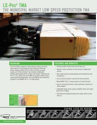
System OverviewThe <strong>REACT</strong> 350 ® <strong>II</strong> system, through crash testing, has been shown to be a potentially reusable,redirective, non-gating, crash cushion for hazards up to 914 mm (3’) wide. After those impactsobserved within NCHRP 350 criteria, it has been observed that, potentially, the entire bulk of thesystem can be reused. What constitutes a potentially reusable highway product should only bedetermined by a trained engineer, experienced in highway products, directed by the appropriatehighway authority.When impacted under NCHRP 350* criteria, this system is capable of shielding specifiedhazards up to 914 mm (3’) wide. It consists of a series of “smart plastic” Cylinders attached to asteel Base Track. The term “smart plastic” refers to the memory characteristics of the Cylinders.After a head-on impact as described in NCHRP 350, the <strong>REACT</strong> 350 ® <strong>II</strong> system has thepotential to recover a major portion of its shape, position, and energy absorbing capability.The <strong>REACT</strong> 350 ® <strong>II</strong> system utilizes various Cylinder wall thicknesses to accommodate both lightcars and heavier, high-center-of-gravity vehicles.Two backup options are available to further meet specific requirements of each location. A Self-Contained Backup is available, or the <strong>REACT</strong> 350 ® <strong>II</strong> system can be mounted to a new orexisting Concrete Backup. In some locations, either Backup type may be applicable.*NCHRP Report National Cooperative Highway Research Program Report 350Self-ContainedBackup ShownConcrete Backup (Optional)Right Side of SystemLeft Side of SystemFigure 1 - <strong>REACT</strong> 350 ® <strong>II</strong> with Self-Contained Backupwww.energyabsorption.com Revision A July 2013www.highwayguardrail.com 7 All rights in copyright reserved
AssemblyRecommended ToolsDocumentationManufacturer’s Instructional ManualManufacturer’s Drawing PackageCutting equipmentGrinder/Hacksaw or TorchRebar cutting bitRotary Hammer Drill22 mm (7/8”) x 178 mm (7”) Concrete Drill Bit (Double Fluted)19 mm (3/4”) x 178 mm (7”) Concrete Drill Bit (Double Fluted)Note: <strong>Energy</strong> <strong>Absorption</strong> <strong>Systems</strong> recommends using double fluted drill bits to achieveoptimum tensile strength when applying the MP-3 ® anchoring system. That decision must beconfirmed with the highway authority authorizing the assembly so it is anchored to theirspecification.HammersSledgehammerWrenchesHeavy duty impact wrench1/4”, 5/16”, 3/8”, 3/4”, 1 7/8" sockets3/4”, 1 1/16”, 1 1/8”, 1 1/4” Deep Hex-head SocketsRatchet and extensions for above socketsStandard adjustable wrench1 1/16”, 1 1/8”, 1 1/4”, 9/16”, 5/8” combination wrenchesLarge Pipe WrenchScrewdriversScrew gun or standard drill with adapter chuck for small screws/boltsFlat ScrewdriverPhillips ScrewdriverPersonal protective equipmentSafety GlassesGlovesApron for MP-3 ® applicationSafety-Toe Shoeswww.energyabsorption.com Revision A July 2013www.highwayguardrail.com 8 All rights in copyright reserved
Miscellaneous Traffic control equipment Lifting and moving equipment (A lifting device is preferred although a forklift can beused.) Minimum 2722 kg [6,000 lb.] capacity required. Do not lift overhead. Compressor (100 psi) and Generator (5 KW) Long pry bar Drift pin Tape measure 7.5 m (25’) Chalk line Nylon bottle brush for cleaning drilled holes Rags, water, and solvent for touch-upNote: The above list of tools is a general recommendation. Depending on specific siteconditions and the complexity of the assembly specified by the appropriate highwayauthority, additional or fewer tools may be required. Decisions as to what tools areneeded to perform the job are entirely within the discretion of the specifying highwayauthority and the authority’s selected contractor performing the assembly of the systemat the authority’s specified site.www.energyabsorption.com Revision A July 2013www.highwayguardrail.com 9 All rights in copyright reserved
Know Your <strong>REACT</strong> 350 ® <strong>II</strong> SystemFor specific assembly, maintenance, or repair details refer to the state or specifying agency’sstandard drawing(s) and/or <strong>Energy</strong> <strong>Absorption</strong> <strong>Systems</strong> standard layout drawings.)Figure 2System SizeBackupSelf-Contained ConcreteEffective Length 5.52 m [18'-1 1/2"] 5.52 m [18'-1 1/2"]System Length 6.47 m [21'-2 3/4"] 6.02 m [19'-9"]Effective Width.91 m [3'-0"]System Width 1.19 m [3'-10 3/4"]Height 1.31 m [4'-3 1/2"]www.energyabsorption.com Revision A July 2013www.highwayguardrail.com 10 All rights in copyright reserved
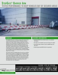
Model Number DescriptionBSelf‐Containedsteel backupTypical hazard width*203 mm [8”]Backup TypeCConcrete Backup withSide Mount AnchorsMax. hazard width914 mm [36”]*See “Hazard Width” on Page 13 for wider hazards.62 6 B 36Nominal system width in inches (width of the cylinders)Backup Type: B or CNumber of BaysMaximum nominal speed in mph (62 mph [100 km/h])Number of BaysA Bay consists of one Cylinder. The terms Bay and Cylinder may be used interchangeably. TheCylinder at the front of the system (traffic end) is always Bay 1, and each subsequent bay issequentially numbered to the rear of the system (hazard end).ConcreteBackupSelf-ContainedBackup654321Figure 3Number of Bayswww.energyabsorption.com Revision A July 2013www.highwayguardrail.com 11 All rights in copyright reserved
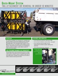
Backup TypeIt is important to fully understand the limitations of each backup type so the correct <strong>REACT</strong> 350 ®<strong>II</strong> system is chosen for each location.The <strong>REACT</strong> 350 ® <strong>II</strong> system is available with a Self-Contained Backup or may be attached to aConcrete Backup. Refer to Figures 4a and 4b, along with the backup assembly drawings, todetermine which type of backup is appropriate.Self-Contained Backup<strong>REACT</strong> 350 ® <strong>II</strong> System with a Self-Contained “steel tube” Backup require two cables, one cableon each side of the Cylinders. These cables begin at the front of the system, travel through theCable Guides on the Cylinders, loop around the backup structure, travel back through the CableGuides, and terminate at the front of the system.Concrete Backup<strong>REACT</strong> 350 ® <strong>II</strong> System with a Concrete Backup requires four cables. Two cables on each sideof the Cylinders begin at the Side Anchor Plates, travel through the Cable Guides on theCylinders, loop around the pin on the Front Anchor Plates, travel back through the CableGuides, and terminate at the Side Anchor Plates.Existing concrete structures may serve as backups for <strong>REACT</strong> 350 ® <strong>II</strong> system provided theymeet specific size and strength requirements.ConcreteBackupOne Cable, Two RunsSelf-ContainedBackupTwo Cables, Four RunsFigure 4aFigure 4bwww.energyabsorption.com Revision A July 2013www.highwayguardrail.com 12 All rights in copyright reserved
System DesignSelf-Contained BackupThe <strong>REACT</strong> 350 ® <strong>II</strong> system with a Self-Contained Backup is intended to minimize assemblytime. This type of system arrives at the site fully assembled. The assembly crew needs only tolift and place the system in front of the barrier then drill and set the anchors. Refer to the“Assembly” section on Page 22 for a complete list of instructions.Hazard WidthGenerally, the <strong>REACT</strong> 350 ® <strong>II</strong> system with a Self-Contained Backup can shield obstacles to 203mm [8”] wide in a gore application. This type of system can also shield wider hazards in nongoreand bidirectional traffic locations (See “Bidirectional Traffic” on Page 14 and “Offsetting theSystem” on Page 15). Please contact <strong>Energy</strong> <strong>Absorption</strong> <strong>Systems</strong> for additional wide hazardinformation (See Page 3).When shielding median barriers (813 mm [32”] tall safety shape), a Self-Contained Backup maybe used if the base or “toe” of the barrier is tapered to a total width of 330 mm [13”] (See Figure5).Taper "Toe" ofBarrierFigure 5Tapered BarrierGuardrail AttachmentHardware is available to mount W-beam guardrail or a safety shaped barrier to the Self-Contained Backup of the <strong>REACT</strong> 350 ® <strong>II</strong> system. A folded Transition Plate and W-beamconnector can mount to either or both sides of the backup assembly (See Figure 6). Ifbidirectional traffic is present, special post spacing, rail, and rub-rail will be required for theguardrail.www.energyabsorption.com Revision A July 2013www.highwayguardrail.com 13 All rights in copyright reserved
Transition PlateP/N 6161483/4" Hex NutP/N 115953W-Beam End ShoeP/N 1148983/4" BoltP/N 113548Figure 6Guardrail Attachment HardwareBidirectional TrafficIf bidirectional traffic (vehicles traveling opposite directions on either side of the system) ispresent, special consideration needs to be taken when placing the system. It is important thatthe Self-Contained Backup does not become a hazard to the reverse direction traffic. If asystem is placed in a location where traffic will be approaching from the rear of the system,transition hardware may be required.Optionally, if space permits, the <strong>REACT</strong> 350 ® <strong>II</strong> system may be offset so that the backupstructure is shielded by the hazard (See “Offsetting the System” on Page 15). Guardrailtransition hardware may also be used.Figure 7Bidirectional Trafficwww.energyabsorption.com Revision A July 2013www.highwayguardrail.com 14 All rights in copyright reserved
Offsetting the SystemIf space permits, <strong>REACT</strong> 350 ® <strong>II</strong> system, with a Self-Contained Backup, may be offset from thecenter of the hazard. Offsetting may be necessary for two reasons:1) To shield a hazard wider than 200 mm [8”]2) If bidirectional traffic is presentWhen offsetting the system, align the vertical face of the Backup structure with the face of thebarrier (See Figure 8). With this method, <strong>REACT</strong> 350 ® <strong>II</strong> system with Self-Contained Backupmay shield hazards up to 610 mm [24”].If a wider hazard is present or if bidirectional traffic is present, a Concrete Backup may berequired. Contact <strong>Energy</strong> <strong>Absorption</strong> <strong>Systems</strong> Customer Service Department for furtherinformation.Concrete BackupFigure 8Offsetting the systemThe <strong>REACT</strong> 350 ® <strong>II</strong> system is also intended to mount directly to a new or existing ConcreteBackup. This type of system requires slightly more assembly time, as the cables must beassembled on site (See the “Assembly” section “<strong>Systems</strong> with Concrete Backups” on Page 26for a complete list of instructions).Existing Concrete Backups must be a minimum of 1000 mm [40”] high, 610 mm [24”] long, and762 mm [30”] to 914 mm [36”] wide, with 28-day strength of 28 MPa [4000 psi] and fullyreinforced.If your existing structure does not meet these minimums, special hardware and designs may beavailable for them. Contact <strong>Energy</strong> <strong>Absorption</strong> <strong>Systems</strong> Customer Service Department if youhave questions concerning Concrete Backup requirements (See Page 3).www.energyabsorption.com Revision A July 2013www.highwayguardrail.com 15 All rights in copyright reserved
Hazard WidthThe <strong>REACT</strong> 350 ® <strong>II</strong> system with a Concrete Backup may be specified to protect obstacles up to914 mm [36”] wide. The backup must be 762 mm [30”] to 914 mm [36”] wide to use standardside anchor hardware.Bidirectional TrafficIf bidirectional traffic (vehicles traveling opposite directions on either side of the system) ispresent, special consideration needs to be taken when placing the system.It is important for the highway design engineer and the assembler to ensure that the ConcreteBackup itself does not become a hazard to the reverse direction traffic. If the system is placed ina location where traffic will be approaching from the rear of the system, the Backup should notprotrude beyond the hazard being shielded. Concrete tapering may be required.Also, an additional standard Side Anchor Plate should be rotated 180 degrees and placedbehind the first anchor plate (See Figure 9). In this case, the backup must be 762 mm [30”] long.Additional SideAnchor PlateFigure 9Standard Anchor Plate with Concrete Backupwww.energyabsorption.com Revision A July 2013www.highwayguardrail.com 16 All rights in copyright reserved
Foundation/AnchoringConcrete InstallationsFor concrete installations, the <strong>REACT</strong> 350 ® <strong>II</strong> system should be installed only on an existing orfreshly placed and cured concrete base (28 MPa [4000 psi] minimum). Orientation of theconcrete base and the attenuator must comply with the project plans or as otherwisedetermined by the resident project engineer or appropriate highway authority.Recommended dimension and reinforcement specifications for new concrete pads can be foundon the standard drawings.Asphalt InstallationsFor asphalt installations in construction zones, <strong>REACT</strong> 350 ® <strong>II</strong> system may only be assembledwith a Tension-Strut Backup. Assemblies on asphalt must provide a minimum of 76 mm [3”]layer of asphalt over a minimum of 76 mm [3”] layer of Portland Cement concrete, 152 mm [6”]layer of asphalt over 152 mm [6”] layer of subbase, or 203 mm [8”] layer of asphalt with nosubbase. 460 mm [18”] threaded rods, installed with the two-part MP-3 ® grout, must be used forthese foundations.Important: <strong>Systems</strong> mounted on asphalt must be replaced and mounted onfresh, undisturbed asphalt if more than 10% of anchors are found to be loose,broken, or show signs of pull out. If 10% or fewer anchors are damaged, replacethe damaged anchors in the existing asphalt. Anchor bolts used on systemsmounted on asphalt must be inspected every 6 months. See Post ImpactInstructions and Maintenance and Repair instructions in the <strong>REACT</strong> 350 ® <strong>II</strong>Assembly Manual for details.The <strong>REACT</strong> 350 ® <strong>II</strong> system may be installed on any of the following foundations using thespecified anchorage:Foundation A: Concrete Pad or RoadwayFoundation: 150 mm [6”] minimum depth Portland Cement Concrete (P.C.C.)Anchorage: MP-3 ® with 180 mm [7”] studs 140 mm [5 1/2”] embedmentFoundation B: Asphalt over P.C.C.Foundation: 76 mm [3”] minimum asphalt concrete (A.C.) over 76 mm [3”] minimum P.C.C.Anchorage: Length of anchor required is 460 mm [18”] 420 mm [16 1/2”] embedmentFoundation C: Asphalt over SubbaseFoundation: 150 mm [6"] minimum A.C. over 150 mm [6”] minimum Compacted Subbase(C.S.)Anchorage: MP-3 with 460 mm [18"] studs 420 mm [16 1/2”] embedmentFoundation D: Asphalt OnlyFoundation: 200 mm [8”] minimum A.C.Anchorage: MP-3 with 460 mm [18”] studs - 420 mm [16 1/2”] embedmentFoundation Specificationsfor Foundations A, B, C, and D mentioned above:www.energyabsorption.com Revision A July 2013www.highwayguardrail.com 17 All rights in copyright reserved
A. C. (Asphalt Concrete)AR-4000 A. C. (per ASTM D3381 '83) 3/4” Maximum, Medium (Type A or B) aggregateSieve SizeOperating Range (%) Passing1" 1003/4" 95-1003/8" 65-80No. 4 49-54No. 8 3 6-40No. 30 1 8-21No. 200 3-8Caution: Walk-up inspections are recommended at least once every sixmonths for installations on asphalt.P.C.C. (Portland Cement Concrete)Stone aggregate concrete mix4000 psi minimum compressive strength(Sampling per ASTM C31-84 or ASTM C42-84a, testing per ASTM C39-84)C.S. (Compacted Subbase)150 mm [6”] minimum depth 95% compactionClass 2 aggregateSieve Size Moving Average % Passing3" 1002 1/2" 90-100No. 4 40-90No. 200 0-25Figure 10a Below-Grade Anchor BlockFigure 10b - Anchor Block Not Neededwww.energyabsorption.com Revision A July 2013www.highwayguardrail.com 18 All rights in copyright reserved
Foundation/Anchoring AssistanceContact <strong>Energy</strong> <strong>Absorption</strong> <strong>Systems</strong> Customer Service Department if you would like input as toyour specific application. Proper model selection is essential to the performance of the <strong>REACT</strong>350 ® <strong>II</strong> system. You will need to answer the following questions:1. Are curbs, islands, or elevated objects (delineators or signs) present at the site? Whatheight and width are they? All curbs and elevated objects should be removed. Curbsshould be removed from behind the backup to approximately 15 m [50’] in front of the<strong>REACT</strong> 350 ® <strong>II</strong> System. Any curbs that must remain should be 102 mm [4”] maximumand be mountable. Signs should not interfere with the system’s ability to collapse.Generally, a vehicle should not interact with two appurtenances at the same time. Allowadequate spacing.2. If the deployment site is a gore area (place where two roads diverge), what is the angleof divergence?3. What is the general geometry of the site? Include the roadway for 150 m [500’] in front ofthe hazard, so traffic patterns can be visualized.4. Is there an existing guardrail or median barrier at the site?5. What is the width of the hazard to be protected?6. Will there be traffic approaching from the rear of the system? Is the system in a two-waytraffic situation with traffic going in opposite directions on either side of the system? Or,is the system on the side of the road where cross over traffic is a concern? If so, atransition from the hazard to the rear of the system may be necessary to prevent avehicle from interacting with the rear of the system (See “Bidirectional Traffic” on Pages13 and 15).7. Are there any other unique features at the site that may affect the positioning orperformance of the <strong>REACT</strong> 350 ® <strong>II</strong> system? See “Other Factors That May Affect YourSpecification on Page 20.www.energyabsorption.com Revision A July 2013www.highwayguardrail.com 19 All rights in copyright reserved
Other Factors That May Affect Your Specification1. The existence of drain inlets or buried culvert pipe.2. Junction boxes or other appurtenances located near the hazard.3. Insufficient space for the length of system preferred.4. The location and movement of expansion joints.5. Breaking cross-slopes under or near the proposed assembly or severe cross-slopeunder the system. Provide leveling to 8% maximum.Figure 11 - 1:12 Cross-SlopeWarning: The existence of any cross slopes in excess of 8% or curbs maycreate an untested effect on the impacting vehicle.www.energyabsorption.com Revision A July 2013www.highwayguardrail.com 20 All rights in copyright reserved
JointsThe <strong>REACT</strong> 350 ® <strong>II</strong> system may span longitudinal joints; however, custom hardware may berequired.The <strong>REACT</strong> 350 ® <strong>II</strong> system may also span a transverse joint if the joint falls under the frontsection of Base Track. In this case, the front section of Base Track should be cut after assemblyso as not to span the joint with structural steel. Never cut the rear section of Base Track. Thejoint movement must be limited to 38 mm [1.5”].Transverse JointLongitudinal JointFigure 12 - Longitudinal or Transverse Jointswww.energyabsorption.com Revision A July 2013www.highwayguardrail.com 21 All rights in copyright reserved
Inspect ShipmentBefore assembling the <strong>REACT</strong> 350 ® <strong>II</strong> system at a specified location, check the received partsagainst the shipping list supplied with the system. Make sure all parts have been received. TheSystem is shipped assembled. All assembly hardware can be found in the last Cylinder. ThePullout Assembly should be stored for post impact use.Assembly ProceduresNote: The drawing assembly package provided with the <strong>REACT</strong> 350 ® <strong>II</strong> system must beused with these instructions for proper assembly and should take precedence over thesegeneral instructions.1) Deploy Traffic ControlA traffic control plan appropriate to the complexity of the project should be prepared andunderstood by all parties before the <strong>REACT</strong> 350 ® <strong>II</strong> system is assembled. Follow the planset forth by the highway authority specifying the use of this system.Deploy the appropriate work zone safety devices prior to beginning the assembly and keepthem present through all phases of deployment.Warning: The correct safety equipment and traffic management systemapproved by the requisite highway authority must be used as required for anyassembly using the <strong>REACT</strong> 350 ® <strong>II</strong> system.www.energyabsorption.com Revision A July 2013www.highwayguardrail.com 22 All rights in copyright reserved
2) Determining the Base Point & CenterlineTypically the base point of the <strong>REACT</strong> 350 ® <strong>II</strong> system will be the midpoint of the hazard at itsfront face. This may change if bidirectional traffic or expansion joints are present (See“Offsetting the System” on Page 15).Extend a chalk line from the base point, perpendicular to the hazard face, or as determinedby project engineer, to a distance greater than the maximum length of the <strong>REACT</strong> 350 ® <strong>II</strong>system (refer to the drawings provided). This chalk line will become the centerline for the<strong>REACT</strong> 350 ® <strong>II</strong> system (See Figure 13).Hazard90 ○Figure 13 - PlacementCenterline3) Lifting/Placing the SystemMark the centerline on the front and rear of the Base Track. Use the Lifting Eyes located onthe Middle Rail of the Rear Base Track (look down into the Cylinders) to lift the <strong>REACT</strong> 350 ®<strong>II</strong> system into place (See Figure 14).Use fixed-length slings with a 2722 kg [6,000 lb.] minimum capacity. Fixed slings will preventthe System from tipping. Do not lift overhead. Measure from the centerline to ensure that the<strong>REACT</strong> 350 ® <strong>II</strong> system is centered and positioned at the proper angle. The steel Base Trackwill rest flush against the hazard face for assemblies that do not require transitions.www.energyabsorption.com Revision A July 2013www.highwayguardrail.com 23 All rights in copyright reserved
Lifting EyesFigure 14 - Lifting Eye LocationWarning: Ensure the hoist device is properly rated to lift the <strong>REACT</strong> 350 ® <strong>II</strong>system.For Self-Contained Backup assemblies requiring transition hardware to concrete wall orsafety shape barrier (P/N 616120), the steel Base Track should be 127 mm [5”] forward ofthe hazard face (See Figure 15).127 mm [5"]BarrierTransition HardwareRequired to Help PreventSnagging of Impacting VehicleP/N 616120Figure 15 – Transition Hardware<strong>Systems</strong> with Self-Contained BackupsNote: For <strong>Systems</strong> with Concrete Backups, please skip to Page 26.www.energyabsorption.com Revision A July 2013www.highwayguardrail.com 24 All rights in copyright reserved
4) Drill and Set AnchorsUse the holes in the Base Track as a template to locate and drill holes, 22 mm [7/8”]diameter x 140 mm [5 1/2”] deep into the concrete pad or roadway surface (see Figure 16).All holes in Base Plate must be used to anchor the <strong>REACT</strong> 350 ® <strong>II</strong> System to the foundation.Use vertical MP-3 ® kits to attach 3/4” diameter x 7 1/2” long studs using instructions includedwith kit. Refer to the MP-3 ® Polyester Anchoring System section on Page 34 for step-by-stepinstructions.After grout has hardened, use 3/4” flat washers and nuts provided with kit to anchor basetrack to foundation.Warning: All holes in Base Plate must be used to anchor the <strong>REACT</strong> 350 ® <strong>II</strong>system to the foundation.Warning: Once the grout has hardened, see Table B on Page 36 for hardeningtimes, torque nuts to 165 N-m [120 ft-lb].AnchorLocationsSelf-ContainedBackupAnchorLocationsAnchorLocationsAnchorLocationsFigure 16 - Anchoring the System - Self-Contained Backupwww.energyabsorption.com Revision A July 2013www.highwayguardrail.com 25 All rights in copyright reserved
5) Tension Restraining CablesUse the two adjusting nuts at the rear of the Backup to tension the cables (See Figure 17).When properly tensioned, the cables should not deflect more than 75 mm [3”] with 45 kg[100 lb.] downward pressure.Restraining CableTensionAdjustmentP/N 605808Concrete Backups1) Rear Cylinder AttachmentFigure 17 - Tension Adjustment (Self-Contained Backup)Use the holes in the Rear Cylinder as a template to locate and drill two holes, 22 mm [7/8”]diameter x 140 mm [5 1/2”] deep into the Concrete Backup (See Figure 18). Use horizontalMP-3 ® kit to attach 3/4” diameter x 7 1/2” long studs using instructions included with kit.Refer to MP-3 ® Polyester Anchoring System on Page 34 for step-by-step instructions. Aftergrout has hardened, use 3/4” nuts and flat washers included with MP-3 ® kits to attachCylinder Assembly to Backup as shown in Figure 18.2) Drill and Set AnchorsUse the holes in the Base Track as a template to locate and drill holes, 22 mm [7/8”]diameter x 140 mm [5 1/2”] deep into the concrete pad or roadway surface (See Figure 18).Use Vertical MP-3 ® kits to attach 3/4” diameter x 7 1/2” long studs using instructionsincluded with kit. Refer to MP-3 ® Polyester Anchoring System on Page 34 for step-by-stepinstructions. After grout has hardened, use 3/4” flat washers and nuts provided with kit toanchor base track to foundation.Warning: All holes in Base Plate must be used to anchor the <strong>REACT</strong> 350 ® <strong>II</strong>system to the foundation.www.energyabsorption.com Revision A July 2013www.highwayguardrail.com 26 All rights in copyright reserved
Warning: Once the grout has hardened, see Table B on Page 36 for hardeningtimes, torque nuts to 165 N-m [120 ft-lb].ConcreteBackupAnchorLocationsAnchorLocationsAnchorLocationsAnchorLocationsFigure 18 - Anchoring the System - Concrete Backupwww.energyabsorption.com Revision A July 2013www.highwayguardrail.com 27 All rights in copyright reserved
3) Drill and Set Side Anchor Plate AnchorsWarning: For <strong>REACT</strong> 350 ® <strong>II</strong> system with a Concrete Backup, Side CableAnchor Plates must be attached.Warning: The vertical placement of the Side Anchor Plates is critical to theperformance of the <strong>REACT</strong> 350 ® <strong>II</strong> system. If an existing backup is not tallenough to fulfill these requirements, special brackets are available. Consult<strong>Energy</strong> <strong>Absorption</strong> <strong>Systems</strong> Customer Service for further information.When correctly assembled, the top of the Side Cable Anchor Plates should be 991 mm (39”)from the road surface. The front edge of the Side Cable Anchor Plates should be 51 mm -102 mm [2” - 4”] from the front face of the backup to avoid reinforcing steel. The taperedside of the Side Cable Anchor Plates should face the front of the System (see Figure 19).Use the holes in the Side Cable Anchor Plates as templates to match drill ten holes per sideof backup, 22 mm [7/8”] diameter x 140 mm [5 1/2”] deep into the Concrete Backup. Usehorizontal MP-3 ® kit to place twenty 3/4” diameter x 6 1/2” long studs using instructionsincluded with kit. After grout has hardened, use 3/4” flat washers and nuts provided with kitto attach side cable anchor plates (one on each side) to Concrete Backup as shown inFigure 19.Warning: Once the grout has hardened, see Table B on Page 36 forhardening times, torque nuts to 165 N-m [120 ft-lb].76 mm [3"]991 mm[39"]Side CableAnchor PlatesP/N 614195Tapered SideFigure 19 - Side Cable Anchor Plateswww.energyabsorption.com Revision A July 2013www.highwayguardrail.com 28 All rights in copyright reserved
4) Attach Restraining CablesWarning: Four Restraining Cables must be attached; two on each side ofbackup.A. Slide the threaded end of a Restraining Cable through the third guide down andattach flat washer and nut as shown in Figure 20. Tighten the nut so it is flush withthe end of the threaded end of cable.WedgeP/N 118127FerruleP/N 114932Side CableAnchor PlateP/N 6141957/8" Flat WasherP/N 118028Nut & Flat WasherP/N 115917 & 118001Threaded Endof CableFigure 20 - Routing First CableB. Route the Restraining Cable through the Cable Guides on the sides of the Cylinders,around the Restraining Cable Pin as shown in Figure 21, back through the TopCable Guides on the Cylinders and through the Top Cable Guide of the Side Plate(See Figure 22).www.energyabsorption.com Revision A July 2013www.highwayguardrail.com 29 All rights in copyright reserved
Restraining Cables1/4" Nut & Lock WasherP/N 115946 & 118085RestrainingCable PinP/N 6120401/4" BoltP/N 113512Figure 21 -Front of System Cable Attachment (Concrete Backup)3. Pull on the cut end of the cable removing all possible slack. Slide the 7/8” x 3” flatwasher and the ferrule (in that order) over the end of the non-threaded end of theRestraining Cable. Mark the cable 50 mm [2”] back from the ferrule. Leaving theferrule and washer in place, cut the cable at the mark with a grinder or hack saw. Donot use a torch to cut the cable. Unbraid end of cable and insert middle strandbetween the two halves of the wedge. Carefully wrap the remaining six strands intothe two halves of the wedge. Carefully wrap the remaining six strands into the slotsaround the wedge then push into ferrule to tighten (See Figure 22 and Detail A). Usea drift pin and sledge hammer to seat the ferrule into the cable receptacles.Repeat these steps for remaining three Restraining Cables ensuring that the threadedends of the Restraining Cables are attached through the lower two guides as shown inFigure 22.NutThreaded Ends ofRestraining CablesFigure 22 – Rear Cable AttachmentConcrete BackupDetail A – Cable Ferrulewww.energyabsorption.com Revision A July 2013www.highwayguardrail.com 30 All rights in copyright reserved
5) Tension Restraining CablesUse the nuts on the threaded end of the cables to tension the cables (See Figure 22).When properly tensioned, the cables should not deflect more than 75 mm [3”] with 45 kg[100 lb.] downward pressure.Attach Nose Cover1. Ensure appropriate Nose Cover is attached (See Figure 23). The Nose Cover Selectionbelow will assist in your selection and you should refer to local standards and “Manualon Uniform Traffic Control Devices” (MUTCD) for nose.Barrier Barrier BarrierTraffic Traffic Traffic TrafficTraffic on Right Traffic on Both Sides Traffic on LeftSide of System of System Side of SystemFigure 23 - Nose Cover Selection2. Align 1” diameter hole in Nose Cover with 1” diameter hole in Cylinder (See Figure 24).3. Screw 1/4" self-drilling screw into Cylinder punching through reflective tape and into theexisting holes in Nose Cover until head of fastener is flush (10 places) (See Detail B).Align 1" Hole(For Assembly ofSystem Pullout DeviceSeeDetail BNose CoverP/N 617966 - R & LP/N 617965 - GoreFigure 24 - Nose Cover AttachmentDetail B1/4" Self-DrillingP/N 116891www.energyabsorption.com Revision A July 2013www.highwayguardrail.com 31 All rights in copyright reserved
Affix Side Mount ReflectorsRefer to local standards and “Manual on Uniform Traffic Control Devices” (MUTCD) forreflectors.For Side Mount Reflectors, attach to traffic side(s) of the system with the white side facingtraffic by screwing #8 self-tapping screws through the reflector and into the Cylinder untilhead of fastener is flush (2 places per reflector) (See Figure 25).White Facing Traffic,Amber Opposite50 mm [2"]ReflectorP/N 611305Figure 25 - Side Mounted Reflector#8 Flat WasherP/N 117989#8 Self-Drilling ScrewP/N 116943www.energyabsorption.com Revision A July 2013www.highwayguardrail.com 32 All rights in copyright reserved
Optional Debris CoversTo attach Optional Debris Covers, center a cover on Cylinder 1. Note the orientation of thegrommets. The two grommets closest together should be located in the front or rear of theCylinder (See Figure 26).[770 mm][445 mm]Direction of ImpactFigure 26Next attach the four #10 flat head screws and fender washers ensuring the screw is positionedin the middle of the Cylinder wall (See Figure 27).Figure 27Continue to attach the remaining covers as described above.Note: The covers may overlap; however, the overlap direction is not critical to systemperformance.www.energyabsorption.com Revision A July 2013www.highwayguardrail.com 33 All rights in copyright reserved
MP-3 ® Polyester Anchoring SystemThe MP-3 ® Polyester Anchoring System is a quick and easy way to securely anchor crashcushions and other common highway devices. MP-3 ® features high pullout strength, superiorvibration resistance, and exceptional durability.Each MP-3 ® kit contains a can of MP-3 ® resin, hardener, cold-weather promoter, studs,washers, nuts, and a complete safety sheet. The cold-weather promoter shortens hardeningtime by as much as seven hours. Both vertical and horizontal assemblies are possible using theMP-3 ® system.Warning: Read MP-3 ® Instructions before starting.Warning: Do not allow the MP-3 ® Resin or Hardener to contact skin or eyes.See material safety data sheet supplied with the MP-3 ® kit for first aidprocedures. Use only in well-ventilated area. Do not use near open flame.Warning: Wear safety goggles and gloves during assembly.Vertical Assemblies1) Prepare the concrete padThe anchor bolts (studs) that anchor the <strong>REACT</strong> 350 ® <strong>II</strong> System to the concrete pad mustbe those shipped in the kit or of high strength steel (830 MPa [120,000 psi] minimum tensilestrength). These studs must be set in minimum 28 MPa [4000 psi] concrete. Allow theconcrete to cure a minimum of seven days before applying MP-3 ® .2) Drill holesNote: <strong>Energy</strong> <strong>Absorption</strong> <strong>Systems</strong> recommends using double fluted drill bits to achieveoptimum tensile strength when assembling the MP-3 ® anchoring system. That decision must beconfirmed with the highway authority authorizing the assembly and that it is assembled to theirspecification.Use the part that is to be anchored as a drilling template. Drill the holes 3 mm [1/8”] largerthan the stud diameter to the recommended depth with a rotary hammer drill. Full strengthwill not be achieved if a diamond bit is used. Refer to the MP-3 ® Assembly instructionsprovided with your kit. Check to be sure all the holes are drilled to the proper depth andaligned with the part to be anchored (See Table A).www.energyabsorption.com Revision A July 2013www.highwayguardrail.com 34 All rights in copyright reserved
3) Clean the holesTable A: MP-3 ® Polyester Anchoring Information3/4” Ø StudLengthConcreteBit SizeMinimumDepthRecommendedTorque6 1/2”22 mm 125 mm 165 N-m[7/8”] [5”] [120 ft-lb]7” 22 mm 140 mm 165 N-m7 1/2” [7/8”] [5 1/2”] [120 ft-lb]8 1/2”18”22 mm 420 mm
7) Add the washers and nutsPlace a flat washer onto the stud; then thread a nut on until 1 or 2 threads of the NUT areleft exposed (See Figure 28).CorrectIncorrectFigure 28 - MP-3 ® Vertical Assembly8) Insert Studs in holes and wait for grout to hardenPush the stud down through the part to be anchored and into the hole. Give the stud severaltwists in the MP-3 ® to wet the threads.Warning: Do not disturb or load the stud until the MP-3 ® material has hardened(See Table B).Table B: Approximate Hardening TimesTemperatureNoPromoterWith Promoter(C) (F) (time in hours)>26 >80 1/2 N/R*22-26 70-79 1 N/R*16-21 60-69 2 N/R*10-15 50-59 4 3/44-9 40-49 8 1-1 -3 30-39 N/R* 1 1/2
Horizontal AssembliesThe Horizontal MP-3 ® kit is the same as the vertical kit except that a cartridge for a standardcaulking gun is supplied in the horizontal kits and the resin for the horizontal kits is a Thixotropic(TX) Resin. The TX-Resin is a gelled resin designed to keep the grout in place in horizontalholes during assembly.When using the Horizontal MP-3 ® kits, follow the vertical instructions with the followingexceptions:1) Thread dispensing tip onto dispenserPrior to mixing the grout, carefully thread the dispensing tip onto the dispenser.2) Pour mixed grout into dispenserOnce the grout is mixed, crimp the mouth of the can to form a spout and pour the MP-3 ®grout into the open end of the dispenser (use mixing stud to scrape out the portionremaining in the can). You may use the box to hold the dispenser upright. Close the box lidand poke the dispenser tip into the top of it. Seal the dispenser with the plunger provided.3) Place dispenser in caulking gun and dispense groutCut off the small end of the dispenser tip. Place the dispenser into a caulking gun anddispense until MP-3 ® TX grout reaches the tip of the dispenser, then release pressure. Pushthe dispenser tip through the part to the bottom of the hole and dispense while slowlywithdrawing the tip. Fill the hole 1/3 to 1/2 full.Warning: Do not overfill or under fill the hole. If the hole is overfilled, there willnot be enough grout to use all of the anchor studs per kit. If hole is under filledthe grout may not develop the required pull out strength.4) Add the washers and nutsPut washer and nut on stud leaving nut flush with end of stud (See Figure 29).5) Insert Studs into holesPush stud through part to be anchored and into hole. Give the stud several twists in theMP-3 ® grout to wet the studs.www.energyabsorption.com Revision A July 2013www.highwayguardrail.com 37 All rights in copyright reserved
Maintenance and RepairThe <strong>REACT</strong> 350 ® <strong>II</strong> system, through crash testing, has been shown to be a potentially reusablecrash cushion. After those impacts observed within NCHRP 350 criteria, it has been observedthat, potentially, the bulk of the system can be reused. However, whether or not a system isreusable is the sole discretion of the highway authority specifying their use.Warning: After an impact, always follow the “Post-Impact Instructions” on Page42.Estimated Time for MaintenanceAn experienced two-person crew with the proper tools and spare parts should be able tocomplete the work in one to three hours depending on the damage done to the system.Life ExpectancyEnvironmentIt is anticipated, given typical environmental conditions that the plastic cylinders will survive in ahighway environment for a period ranging from 5 to 15 years from the date of deploymentunless impact damage renders them otherwise. However, the life of a system in each specificapplication should be determined by the highway authority specifying their use and maintainingthe system.ImpactsPotential life expectancy of the system is also dependent on the impacts. This includes:1. The number of impacts to the system2. The severity of the impacts3. The temperature at the time of the impactsThe <strong>REACT</strong> 350 ® <strong>II</strong> system must be inspected after each impact. Depending on the impact,components may get damaged and need replacement. A cylinder requires replacement whenthe minor axis of the cylinder stays permanently at 460 mm [18”] or less (See Figure 30), or thesystem does not reach 90% of the original length. It is critical that all cables and anchoring bechecked and returned to original assembly conditions. Any parts used in the repair of thesystem must be original <strong>Energy</strong> <strong>Absorption</strong> <strong>Systems</strong> parts (See Page 3).460 mm [18"]Figure 30 - Measure Minor Axiswww.energyabsorption.com Revision A July 2013www.highwayguardrail.com 39 All rights in copyright reserved
Recycling InformationWhen parts need to be replaced, it is recommended that the old parts be recycled as follows:Steel should be sold as scrap to a local metal recycler.HDPE plastic cylinders should be sold to a plastic recycler if available. If a recycler isunavailable, dispose of the material as plastic refuse.Parts Ordering Procedure1. Locate the Product Decal attached to the inside of the Rear Cylinder. Copy the salesorder information from the decal.2. Make a list of any damaged parts, using part numbers and descriptions found on thereference drawings included with the <strong>REACT</strong> 350 ® <strong>II</strong> system.3. Only parts specified to be used in this system may be used during repair. The use of apart not specified in this system design renders this system as one that HAS NOT BEENaccepted by FHWA for use on the National Highway System and all observed crashtesting to determine system performance is negated. The use of a part not containedherein during the repair renders the systems as something other than that which wascrashed and tested accepted by the FHWA for use on the national highway system.InspectionsInspections by the appropriate highway authority are recommended as determined by thatauthority based upon volume of traffic and impact history. Visual drive-by inspections arerecommended at least once every three months. Walk-up inspections are recommended atleast twice a year.Warning: After an impact, always follow the “Post-Impact Instructions” on Page42.Visual Drive-By Inspection1. Check to see if there is evidence of an impact. Check to verify that the <strong>REACT</strong> 350 ® <strong>II</strong>system is fully extended from the backup. If it is not, a walk-up inspection will benecessary to determine the cause.2. Note the location and condition of the <strong>REACT</strong> 350 ® <strong>II</strong> system and the date of visualdrive-by inspection on a log sheet.Warning: Debris, snow, or ice inside the cylinders may prevent the <strong>REACT</strong>350 ® <strong>II</strong> system from absorbing the impact of a crash as observed in NCHRP 350compliant crash testing. Perform a walk-up inspection as needed to check forand dispose of any debris inside the Cylinders. Failing to remove this debris orother material infringes upon the performance of the system observed in FHWAaccepted crash testing.www.energyabsorption.com Revision A July 2013www.highwayguardrail.com 40 All rights in copyright reserved
Walk-Up Inspection1. Check for any foreign matter that may interfere with the smooth operation of the <strong>REACT</strong>350 ® <strong>II</strong> system. Check for and remove any debris found inside the Cylinders. Check forand remove any debris found under and around the <strong>REACT</strong> 350 ® <strong>II</strong> system.2. Check for evidence of bent or damaged parts. Replace as soon as possible (See “PartsOrdering Procedure” on Page 40).3. Verify that all nuts and bolts are tight and rust free.4. Be sure MP-3 ® Concrete Anchor Bolts are securely anchored.5. Verify that all Cylinders are in good condition and properly positioned on the Base Track.Any Cylinder that is cracked or otherwise damaged should be replaced. Measure theminor axis of the Cylinders. Cylinders require replacement when the minor axis of thecylinders measures 460 mm [18”] or less (See Figure 30).6. Ensure all cables are attached with parts specified for use in this system.7. Note the location and condition of the <strong>REACT</strong> 350 ® <strong>II</strong> system and any work done for thedate of this inspection. If further repair is necessary, note the repair requested. Refer tothe standard drawing and assembly section of this Manual for more information.Warning: The correct safety equipment and approved traffic management mustbe used as required for walk-up inspections of the <strong>REACT</strong> 350 ® <strong>II</strong> system.www.energyabsorption.com Revision A July 2013www.highwayguardrail.com 41 All rights in copyright reserved
Post-Impact Instructions1. Deploy the appropriate traffic control devices to protect your crew.Warning: The correct safety equipment and approved traffic management mustbe used as required for walk-up inspections of the <strong>REACT</strong> 350 ® <strong>II</strong> system.2. Check to see that all anchor bolts have remained firmly anchored in the roadway surfaceand in the Concrete Backup, if applicable. Replace any anchors that are loose, broken,or pulled out.3. Clear and dispose of any debris inside the cylinders and on the site.4. Check the condition of the Cylinders. Any Cylinder that is cracked or otherwise damagedshould be replaced. Measure the minor axis of the Cylinders. Cylinders requirereplacement when the minor axis of the Cylinders measures 460 mm [18”] or less (SeeFigure 30).5. The <strong>REACT</strong> 350 ® <strong>II</strong> system must be pulled out to its original length after each impact.The Pullout Assembly must be attached prior to this procedure and removed and storedwhen finished (See Figure 31).Backing TubeP/N 6164071/2"x4"x4" BarWasherP/N 6092363/4" x 7 1/2" StudP/N 1175413/4" NutP/N 1159543/4" x 2" Heavy FlatWasherP/N 1180273/4" Eye NutP/N 115906Figure 31 - Pullout Assemblywww.energyabsorption.com Revision A July 2013www.highwayguardrail.com 42 All rights in copyright reserved
DWG R626B036U<strong>REACT</strong> 350 ® <strong>II</strong> TL-3 w/Self-Contained Backupwww.energyabsorption.com Revision A July 2013www.highwayguardrail.com 43 All rights in copyright reserved
DWG R626C036U<strong>REACT</strong> 350 ® <strong>II</strong> TL-3 w/Concrete Backupwww.energyabsorption.com Revision A July 2013www.highwayguardrail.com 44 All rights in copyright reserved
DWG 3535053-0000<strong>REACT</strong> 350 ® <strong>II</strong> Transition Assembly, SC BU, UNIwww.energyabsorption.com Revision A July 2013www.highwayguardrail.com 45 All rights in copyright reserved
DWG 3535006-0000<strong>REACT</strong> 350 ® <strong>II</strong> Transition Assembly, SC BU, Nwww.energyabsorption.com Revision A July 2013www.highwayguardrail.com 46 All rights in copyright reserved
DWG 3535048-0000 Sheet 1 of 3<strong>REACT</strong> 350 ® <strong>II</strong> Transition Assembly, SC BU, N, w/Rub Railwww.energyabsorption.com Revision A July 2013www.highwayguardrail.com 47 All rights in copyright reserved
DWG 3535048-0000 Sheet 2 of 3www.energyabsorption.com Revision A July 2013www.highwayguardrail.com 48 All rights in copyright reserved
DWG 3535048-0000 Sheet 3 of 3www.energyabsorption.com Revision A July 2013www.highwayguardrail.com 49 All rights in copyright reserved
DWG 605028 Sheet 1 of 2<strong>REACT</strong> 350 ® <strong>II</strong> Basetrack Assembly 36” Wide Unitswww.energyabsorption.com Revision A July 2013www.highwayguardrail.com 50 All rights in copyright reserved
DWG 605028 Sheet 2 of 2www.energyabsorption.com Revision A July 2013www.highwayguardrail.com 51 All rights in copyright reserved
DWG 605020 Sheet 1 of 3<strong>REACT</strong> 350 ® <strong>II</strong> Concrete B-up Basetrack Assembly 36” Wide Unitswww.energyabsorption.com Revision A July 2013www.highwayguardrail.com 52 All rights in copyright reserved
DWG 605020 Sheet 2 of 3www.energyabsorption.com Revision A July 2013www.highwayguardrail.com 53 All rights in copyright reserved
DWG 605020 Sheet 3 of 3www.energyabsorption.com Revision A July 2013www.highwayguardrail.com 54 All rights in copyright reserved
DWG 616084<strong>REACT</strong> 350 ® <strong>II</strong> Transition Assembly for use w/Concrete Backupwww.energyabsorption.com Revision A July 2013www.highwayguardrail.com 55 All rights in copyright reserved
DWG 114054 Sheet 1 of 2<strong>REACT</strong> 350 ® <strong>II</strong> Cast-in-Place Concrete Slab w/Steel Backup 36”www.energyabsorption.com Revision A July 2013www.highwayguardrail.com 56 All rights in copyright reserved
DWG 114054 Sheet 2 of 2www.energyabsorption.com Revision A July 2013www.highwayguardrail.com 57 All rights in copyright reserved
DWG 617967<strong>REACT</strong> 350 ® Nose Cover Assembly TL-3www.energyabsorption.com Revision A July 2013www.highwayguardrail.com 58 All rights in copyright reserved
DWG 606182 Sheet 1 of 2<strong>REACT</strong> 350 ® Chain/CYL Connector Assemblywww.energyabsorption.com Revision A July 2013www.highwayguardrail.com 59 All rights in copyright reserved
DWG 606182 Sheet 2 of 2www.energyabsorption.com Revision A July 2013www.highwayguardrail.com 60 All rights in copyright reserved
DWG 605780 Sheet 1 of 2<strong>REACT</strong> 350 ® Cable Assemblieswww.energyabsorption.com Revision A July 2013www.highwayguardrail.com 61 All rights in copyright reserved
DWG 605780 Sheet 2 of 2www.energyabsorption.com Revision A July 2013www.highwayguardrail.com 62 All rights in copyright reserved
DWG 613705<strong>REACT</strong> 350 ® Reflector Assembly, White/Amber, Sidewww.energyabsorption.com Revision A July 2013www.highwayguardrail.com 63 All rights in copyright reserved
DWG 3535043-0000<strong>REACT</strong> 350 ® Misc. Hardwarewww.energyabsorption.com Revision A July 2013www.highwayguardrail.com 64 All rights in copyright reserved
DWG 606715<strong>REACT</strong> 350 ® 36” Debris Cover Assemblywww.energyabsorption.com Revision A July 2013www.highwayguardrail.com 65 All rights in copyright reserved
DWG 618102<strong>REACT</strong> 350 ® Debris Cover Assemblywww.energyabsorption.com Revision A July 2013www.highwayguardrail.com 66 All rights in copyright reserved
DWG 616716www.energyabsorption.com Revision A July 2013www.highwayguardrail.com 67 All rights in copyright reserved
DWG 3535113-0000<strong>REACT</strong> 350 ® Drivable Pile Anchor Assemblywww.energyabsorption.com Revision A July 2013www.highwayguardrail.com 68 All rights in copyright reserved
DWG 3535054-0000<strong>REACT</strong> 350 ® Sign Post Assembly Instructionswww.energyabsorption.com Revision A July 2013www.highwayguardrail.com 69 All rights in copyright reserved
Notes:www.energyabsorption.com Revision A July 2013www.highwayguardrail.com 70 All rights in copyright reserved
2525 Stemmons FreewayDallas, Texas 75207888-323-6374 (USA only)312-467-6750 (Outside USA)www.energyabsorption.comwww.highwayguardrail.com