74HC08; 74HCT08 Quad 2-input AND gate
74HC08; 74HCT08 Quad 2-input AND gate
74HC08; 74HCT08 Quad 2-input AND gate

Create successful ePaper yourself
Turn your PDF publications into a flip-book with our unique Google optimized e-Paper software.
Philips Semiconductors<strong>Quad</strong> 2-<strong>input</strong> <strong>AND</strong> <strong>gate</strong>Product specification<strong>74HC08</strong>; <strong>74HCT08</strong>FEATURES• Complies with JEDEC standard no. 8-1A• ESD protection:HBM EIA/JESD22-A114-A exceeds 2000 VMM EIA/JESD22-A115-A exceeds 200 V.• Specified from −40 to +85 °C and −40 to +125 °C.DESCRIPTIONThe 74HC/HCT08 are high-speed Si-<strong>gate</strong> CMOS devicesand are pin compatible with low power Schottky TTL(LSTTL). They are specified in compliance with JEDECstandard no. 7A. The 74HC/HCT08 provide the 2-<strong>input</strong><strong>AND</strong> function.QUICK REFERENCE DATAGND = 0 V; T amb =25°C; t r =t f = 6 ns.TYPICALSYMBOL PARAMETER CONDITIONS<strong>74HC08</strong> <strong>74HCT08</strong>UNITt PHL /t PLH propagation delay nA, nB to nY C L = 15 pF; V CC = 5 V 7 11 nsC I <strong>input</strong> capacitance 3.5 3.5 pFC PD power dissipation capacitance per <strong>gate</strong> notes 1 and 2 10 20 pFNotes1. C PD is used to determine the dynamic power dissipation (P D in µW).P D =C PD × V 2 CC × f i × N+Σ(C L × V 2 CC × f o ) where:f i = <strong>input</strong> frequency in MHz;f o = output frequency in MHz;C L = output load capacitance in pF;V CC = supply voltage in Volts;N = total load switching outputs;Σ(C L × V 2 CC × f o ) = sum of the outputs.2. For <strong>74HC08</strong>: the condition is V I = GND to V CC .For <strong>74HCT08</strong>: the condition is V I = GND to V CC − 1.5 V.FUNCTION TABLEINPUTOUTPUTnA nB nYL L LL H LH L LH H HNote1. H = HIGH voltage level;L = LOW voltage level.2003 Jul 25 2
Philips Semiconductors<strong>Quad</strong> 2-<strong>input</strong> <strong>AND</strong> <strong>gate</strong>Product specification<strong>74HC08</strong>; <strong>74HCT08</strong>ORDERING INFORMATIONPACKAGETYPE NUMBERTEMPERATURE RANGE PINS PACKAGE MATERIAL CODE<strong>74HC08</strong>N −40 to +125 °C 14 DIP14 plastic SOT27-1<strong>74HCT08</strong>N −40 to +125 °C 14 DIP14 plastic SOT27-1<strong>74HC08</strong>D −40 to +125 °C 14 SO14 plastic SOT108-1<strong>74HCT08</strong>D −40 to +125 °C 14 SO14 plastic SOT108-1<strong>74HC08</strong>DB −40 to +125 °C 14 SSOP14 plastic SOT337-1<strong>74HCT08</strong>DB −40 to +125 °C 14 SSOP14 plastic SOT337-1<strong>74HC08</strong>PW −40 to +125 °C 14 TSSOP14 plastic SOT402-1<strong>74HCT08</strong>PW −40 to +125 °C 14 TSSOP14 plastic SOT402-1<strong>74HC08</strong>BQ −40 to +125 °C 14 DHVQFN14 plastic SOT762-1<strong>74HCT08</strong>BQ −40 to +125 °C 14 DHVQFN14 plastic SOT762-1PINNINGPIN SYMBOL DESCRIPTION1 1A data <strong>input</strong>2 1B data <strong>input</strong>3 1Y data output4 2A data <strong>input</strong>5 2B data <strong>input</strong>6 2Y data output7 GND ground (0 V)8 3Y data output9 3A data <strong>input</strong>10 3B data <strong>input</strong>11 4Y data output12 4A data <strong>input</strong>13 4B data <strong>input</strong>14 V CC supply voltage2003 Jul 25 3
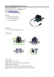
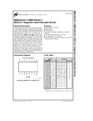
Philips Semiconductors<strong>Quad</strong> 2-<strong>input</strong> <strong>AND</strong> <strong>gate</strong>Product specification<strong>74HC08</strong>; <strong>74HCT08</strong>handbook, halfpage1AV CChandbook, halfpage1A114V CC1B21 14134B1B1Y2A234081312114B4A4Y1Y2A34GND (1)12114A4Y2B5103B2B5103B2YGND697 83A3Y2Y67893AMNA220Top viewGND3YMCE183Fig.1Pin configuration DIP14, SO14 and(T)SSOP14.(1) The die substrate is attached to this pad using conductive dieattach material. It can not be used as a supply pin or <strong>input</strong>.Fig.2 Pin configuration DHVQFN14.handbook, halfpage12451A1B2A2B1Y2Y36handbook, halfpage1245&&3691012133A3B4A4B3Y4Y811910&8MNA2221213&11MNA223Fig.3 Logic symbol.Fig.4 IEC logic symbol.2003 Jul 25 4
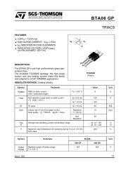
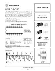
Philips Semiconductors<strong>Quad</strong> 2-<strong>input</strong> <strong>AND</strong> <strong>gate</strong>Product specification<strong>74HC08</strong>; <strong>74HCT08</strong>handbook, halfpage Ahandbook, halfpageAYYBMNB037BMNA221Fig.5 HC logic diagram (one <strong>gate</strong>).Fig.6 HCT logic diagram (one <strong>gate</strong>).RECOMMENDED OPERATING CONDITIONSSYMBOL PARAMETER CONDITIONS<strong>74HC08</strong><strong>74HCT08</strong>MIN. TYP. MAX. MIN. TYP. MAX.UNITV CC supply voltage 2.0 5.0 6.0 4.5 5.0 5.5 VV I <strong>input</strong> voltage 0 − V CC 0 − V CC VV O output voltage 0 − V CC 0 − V CC VT ambt r ,t fambienttemperature<strong>input</strong> rise and falltimessee DC and ACcharacteristics per device−40 +25 +125 −40 +25 +125 °CV CC = 2.0 V − − 1000 − − − nsV CC = 4.5 V − 6.0 500 − 6.0 500 nsV CC = 6.0 V − − 400 − − − nsLIMITING VALUESIn accordance with the Absolute Maximum Rating System (IEC 60134); voltages are referenced to GND (ground = 0 V).SYMBOL PARAMETER CONDITIONS MIN. MAX. UNITV CC supply voltage −0.5 +7.0 VI IK <strong>input</strong> diode current V I < −0.5 V or V I >V CC + 0.5 V − ±20 mAI OK output diode current V O < −0.5 V or V O >V CC + 0.5 V − ±20 mAI O output source or sink current −0.5V
Philips Semiconductors<strong>Quad</strong> 2-<strong>input</strong> <strong>AND</strong> <strong>gate</strong>Product specification<strong>74HC08</strong>; <strong>74HCT08</strong>DC CHARACTERISTICSFamily <strong>74HC08</strong>At recommended operating conditions; voltages are referenced to GND (ground =0V).SYMBOLPARAMETERTEST CONDITIONSOTHERV CC (V)MIN. TYP. MAX. UNITT amb =25°CV IH HIGH-level <strong>input</strong> voltage 2.0 1.5 1.2 − V4.5 3.15 2.4 − V6.0 4.2 3.2 − VV IL LOW-level <strong>input</strong> voltage 2.0 − 0.8 0.5 V4.5 − 2.1 1.35 V6.0 − 2.8 1.8 VV OH HIGH-level output voltage V I =V IH or V ILI O = −20 µA 2.0 1.9 2.0 − VI O = −20 µA 4.5 4.4 4.5 − VI O = −4.0 mA 4.5 3.98 4.32 − VI O = −20 µA 6.0 5.9 6.0 − VI O = −5.2 mA 6.0 5.48 5.81 − VV OL LOW-level output voltage V I =V IH or V ILI O =20µA 2.0 − 0 0.1 VI O =20µA 4.5 − 0 0.1 VI O = 4.0 mA 4.5 − 0.15 0.26 VI O =20µA 6.0 − 0 0.1 VI O = 5.2 mA 6.0 − 0.16 0.26 VI LI <strong>input</strong> leakage current V I =V CC or GND 6.0 − 0.1 ±.0.1 µAI OZ 3-state output OFF current V I =V IH or V IL ; 6.0 − − ±.0.5 µAV O =V CC or GNDI CC quiescent supply current V I =V CC or GND; I O = 0 6.0 − − 2 µA2003 Jul 25 6
Philips Semiconductors<strong>Quad</strong> 2-<strong>input</strong> <strong>AND</strong> <strong>gate</strong>Product specification<strong>74HC08</strong>; <strong>74HCT08</strong>SYMBOLPARAMETERTEST CONDITIONSOTHERV CC (V)MIN. TYP. MAX. UNITT amb = −40 to +85 °CV IH HIGH-level <strong>input</strong> voltage 2.0 1.5 − − V4.5 3.15 − − V6.0 4.2 − − VV IL LOW-level <strong>input</strong> voltage 2.0 − − 0.5 V4.5 − − 1.35 V6.0 − − 1.8 VV OH HIGH-level output voltage V I =V IH or V ILI O = −20 µA 2.0 1.9 − − VI O = −20 µA 4.5 4.4 − − VI O = −4.0 mA 4.5 3.84 − − VI O = −20 µA 6.0 5.9 − − VI O = −5.2 mA 6.0 5.34 − − VV OL LOW-level output voltage V I =V IH or V ILI O =20µA 2.0 − − 0.1 VI O =20µA 4.5 − − 0.1 VI O = 4.0 mA 4.5 − − 0.33 VI O =20µA 6.0 − − 0.1 VI O = 5.2 mA 6.0 − − 0.33 VI LI <strong>input</strong> leakage current V I =V CC or GND 6.0 − − ±1.0 µAI OZ 3-state output OFF current V I =V IH or V IL ; 6.0 − − ±.5.0 µAV O =V CC or GNDI CC quiescent supply current V I =V CC or GND; I O = 0 6.0 − − 20 µA2003 Jul 25 7
Philips Semiconductors<strong>Quad</strong> 2-<strong>input</strong> <strong>AND</strong> <strong>gate</strong>Product specification<strong>74HC08</strong>; <strong>74HCT08</strong>SYMBOLPARAMETERTEST CONDITIONSOTHERV CC (V)MIN. TYP. MAX. UNITT amb = −40 to +125 °CV IH HIGH-level <strong>input</strong> voltage 2.0 1.5 − − V4.5 3.15 − − V6.0 4.2 − − VV IL LOW-level <strong>input</strong> voltage 2.0 − − 0.5 V4.5 − − 1.35 V6.0 − − 1.8 VV OH HIGH-level output voltage V I =V IH or V ILI O = −20 µA 2.0 1.9 − − VI O = −20 µA 4.5 4.4 − − VI O = −4.0 mA 4.5 3.7 − − VI O = −20 µA 6.0 5.9 − − VI O = −5.2 mA 6.0 5.2 − − VV OL LOW-level output voltage V I =V IH or V ILI O =20µA 2.0 − − 0.1 VI O =20µA 4.5 − − 0.1 VI O = 4.0 mA 4.5 − − 0.4 VI O =20µA 6.0 − − 0.1 VI O = 5.2 mA 6.0 − − 0.4 VI LI <strong>input</strong> leakage current V I =V CC or GND 6.0 − − ±1.0 µAI OZ 3-state output OFF current V I =V IH or V IL ; 6.0 − − ±10.0 µAV O =V CC or GNDI CC quiescent supply current V I =V CC or GND; I O = 0 6.0 − − 40 µA2003 Jul 25 8
Philips Semiconductors<strong>Quad</strong> 2-<strong>input</strong> <strong>AND</strong> <strong>gate</strong>Product specification<strong>74HC08</strong>; <strong>74HCT08</strong>Family <strong>74HCT08</strong>At recommended operating conditions; voltages are referenced to GND (ground = 0).SYMBOLPARAMETERTEST CONDITIONSOTHERV CC (V)MIN. TYP. MAX. UNITT amb =25°CV IH HIGH-level <strong>input</strong> voltage 4.5 to 5.5 2.0 1.6 − VV IL LOW-level <strong>input</strong> voltage 4.5 to 5.5 − 1.2 0.8 VV OH HIGH-level output voltage V I =V IH or V ILI O = −20 µA 4.5 4.4 4.5 − VI O = −4.0 mA 4.5 3.84 4.32 − VV OL LOW-level output voltage V I =V IH or V ILI O =20µA 4.5 − 0 0.1 VI O = 4.0 mA 4.5 − 0.15 0.26 VI LI <strong>input</strong> leakage current V I =V CC or GND 5.5 − − ±0.1 µAI OZ 3-state output OFF current V I =V IH or V IL ;V O =V CC or GND;I O =05.5 − − ±0.5 µAI CC quiescent supply current V I =V CC or GND; 5.5 − − 2 µAI O =0∆I CC additional supply current per <strong>input</strong> V I =V CC − 2.1 V; 4.5 to 5.5 − 60 216 µAI O =0T amb = −40 to +85 °CV IH HIGH-level <strong>input</strong> voltage 4.5 to 5.5 2.0 − − VV IL LOW-level <strong>input</strong> voltage 4.5 to 5.5 − − 0.8 VV OH HIGH-level output voltage V I =V IH or V ILI O = −20 µA 4.5 4.4 − − VI O = −4.0 mA 4.5 3.84 − − VV OL LOW-level output voltage V I =V IH or V ILI O =20µA 4.5 − − 0.1 VI O = 4.0 mA 4.5 − − 0.33 VI LI <strong>input</strong> leakage current V I =V CC or GND 5.5 − − ±1.0 µAI OZ 3-state output OFF current V I =V IH or V IL ;V O =V CC or GND;I O =05.5 − − ±5.0 µAI CC quiescent supply current V I =V CC or GND;I O =0∆I CC additional supply current per <strong>input</strong> V I =V CC − 2.1 V;I O =05.5 − − 20 µA4.5 to 5.5 − − 270 µA2003 Jul 25 9
Philips Semiconductors<strong>Quad</strong> 2-<strong>input</strong> <strong>AND</strong> <strong>gate</strong>Product specification<strong>74HC08</strong>; <strong>74HCT08</strong>SYMBOLPARAMETERTEST CONDITIONSOTHERT amb = −40 to +125 °CV IH HIGH-level <strong>input</strong> voltage 4.5 to 5.5 2.0 − − VV IL LOW-level <strong>input</strong> voltage 4.5 to 5.5 − − 0.8 VV OH HIGH-level output voltage V I =V IH or V ILI O = −20 µA 4.5 4.4 − − VI O = −4.0 mA 4.5 3.7 − − VV OL LOW-level output voltage V I =V IH or V ILI O =20µA 4.5 − − 0.1 VI O = 4.0 mA 4.5 − − 0.4 VI LI <strong>input</strong> leakage current V I =V CC or GND 5.5 − − ±1.0 µAI OZ 3-state output OFF current V I =V IH or V IL ;V O =V CC or GND;I O =05.5 − − ±10 µAI CC quiescent supply current V I =V CC or GND;I O =0∆I CC additional supply current per <strong>input</strong> V I =V CC − 2.1 V;I O =0V CC (V)MIN. TYP. MAX. UNIT5.5 − − 40 µA4.5 to 5.5 − − 294 µA2003 Jul 25 10
Philips Semiconductors<strong>Quad</strong> 2-<strong>input</strong> <strong>AND</strong> <strong>gate</strong>Product specification<strong>74HC08</strong>; <strong>74HCT08</strong>AC CHARACTERISTICSFamily <strong>74HC08</strong>GND = 0 V; t f = t f = 6 ns; C L =50pF.SYMBOLPARAMETERTEST CONDITIONSWAVEFORMSV CC (V)MIN. TYP. MAX. UNITT amb =25°Ct PHL /t PLH propagation delay nA, see Figs 7 and 8 2.0 − 25 90 nsnB to nY4.5 − 9 18 ns6.0 − 7 15 nst THL /t TLH output transition time see Figs 7 and 8 2.0 − 19 75 ns4.5 − 7 15 ns6.0 − 6 13 nsT amb = −40 to +85 °Ct PHL /t PLH propagation delay nA, see Figs 7 and 8 2.0 − − 115 nsnB to nY4.5 − − 23 ns6.0 − − 20 nst THL /t TLH output transition time see Figs 7 and 8 2.0 − − 95 ns4.5 − − 19 ns6.0 − − 16 nsT amb = −40 to +125 °Ct PHL /t PLH propagation delay nA, see Figs 7 and 8 2.0 − − 135 nsnB to nY4.5 − − 27 ns6.0 − − 23 nst THL /t TLH output transition time see Figs 7 and 8 2.0 − − 110 ns4.5 − − 22 ns6.0 − − 19 ns2003 Jul 25 11
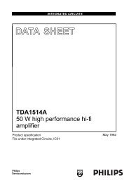
Philips SemiconductorsProduct specification<strong>Quad</strong> 2-<strong>input</strong> <strong>AND</strong> <strong>gate</strong><strong>74HC08</strong>; <strong>74HCT08</strong>Family <strong>74HCT08</strong>GND = 0 V; t f = t f = 6 ns; C L =50pF.SYMBOLPARAMETERTEST CONDITIONSWAVEFORMSV CC (V)MIN. TYP. MAX. UNITT amb =25°Ct PHL /t PLH propagation delay nA, see Figs 7 and 8 4.5 − 14 24 nsnB to nYt THL /t TLH output transition time see Figs 7 and 8 4.5 − 7 15 nsT amb = −40 to +85 °Ct PHL /t PLH propagation delay nA, see Figs 7 and 8 4.5 − − 30 nsnB to nYt THL /t TLH output transition time see Figs 7 and 8 4.5 − − 19 nsT amb = −40 to +125 °Ct PHL /t PLH propagation delay nA, see Figs 7 and 8 4.5 − − 36 nsnB to nYt THL /t TLH output transition time see Figs 7 and 8 4.5 − − 22 nsAC WAVEFORMShandbook, halfpage V InA, nB <strong>input</strong>GNDV MV Mt PHLt PLHV OHnY outputV OL90%V M V M10%t THLt TLHMNA726<strong>74HC08</strong>: V M = 50%; V I = GND to V CC .<strong>74HCT08</strong>: V M = 1.3 V; V I = GND to 3 V.Fig.7 Waveforms showing the <strong>input</strong> (nA, nB) to output (nY) propagation delays and the output transition times.2003 Jul 25 12
Philips SemiconductorsProduct specification<strong>Quad</strong> 2-<strong>input</strong> <strong>AND</strong> <strong>gate</strong><strong>74HC08</strong>; <strong>74HCT08</strong>handbook, halfpageV CCPULSEGENERATORV ID.U.TV OR T C L 50 pFMGK565Definitions for test circuit:C L = Load capacitance including jig and probe capacitance.R T = Termination resistance should be equal to the output impedance Z o of the pulse generator.Fig.8 Load circuitry for switching times.2003 Jul 25 13
Philips Semiconductors<strong>Quad</strong> 2-<strong>input</strong> <strong>AND</strong> <strong>gate</strong>Product specification<strong>74HC08</strong>; <strong>74HCT08</strong>PACKAGE OUTLINESDIP14: plastic dual in-line package; 14 leads (300 mil)SOT27-1DM Eseating planeA 2ALA 1Z14ebb 18w Mc(e ) 1M Hpin 1 indexE170 5 10 mmscaleDIMENSIONS (inch dimensions are derived from the original mm dimensions)UNITmminchesAmax.A 1 A 2 (1) (1)min. max.b b 1 c D E e e 1 L M E M H4.2 0.51 3.20.17 0.02 0.131.731.130.0680.0440.530.380.0210.0150.360.230.0140.00919.5018.550.770.736.486.200.260.242.54 7.620.1 0.33.603.050.140.128.257.800.320.3110.08.30.390.33w0.2540.01(1)Zmax.2.20.087Note1. Plastic or metal protrusions of 0.25 mm (0.01 inch) maximum per side are not included.OUTLINEVERSIONREFERENCESIEC JEDEC JEITAEUROPEANPROJECTIONISSUE DATESOT27-1050G04 MO-001 SC-501-1499-12-2703-02-132003 Jul 25 14
Philips Semiconductors<strong>Quad</strong> 2-<strong>input</strong> <strong>AND</strong> <strong>gate</strong>Product specification<strong>74HC08</strong>; <strong>74HCT08</strong>SO14: plastic small outline package; 14 leads; body width 3.9 mmSOT108-1DEAXcyH Ev MAZ148pin 1 indexA 2A 1L pQ(A ) 3θA17Leb pw Mdetail X0 2.5 5 mmscaleDIMENSIONS (inch dimensions are derived from the original mm dimensions)UNITmminchesAmax.1.75A 1 A 2 A 3 b p c D (1) E (1) e H (1)E L L p Q v w y Z0.250.100.069 0.0100.0041.451.250.0570.0490.250.010.490.360.0190.0140.250.190.01000.00758.758.550.350.34Note1. Plastic or metal protrusions of 0.15 mm (0.006 inch) maximum per side are not included.4.03.80.160.151.270.056.25.80.2440.2281.050.0411.00.40.0390.0160.70.60.0280.0240.250.25 0.10.01 0.01 0.004θ0.70.3 o8o0.028 00.012OUTLINEVERSIONREFERENCESIEC JEDEC JEITAEUROPEANPROJECTIONISSUE DATESOT108-1076E06 MS-01299-12-2703-02-192003 Jul 25 15
Philips Semiconductors<strong>Quad</strong> 2-<strong>input</strong> <strong>AND</strong> <strong>gate</strong>Product specification<strong>74HC08</strong>; <strong>74HCT08</strong>SSOP14: plastic shrink small outline package; 14 leads; body width 5.3 mmSOT337-1DEAXcyH Ev MAZ14 8pin 1 indexA 2A 1L pQ(A ) 3θAL1 7detail Xeb pw M0 2.5 5 mmscaleDIMENSIONS (mm are the original dimensions)AUNIT A 1 A 2 A 3 b p c D (1) E (1) e H E L L p Q v w y Z(1)max.mm20.210.051.801.650.250.380.250.200.096.46.05.45.27.91.03 0.90.65 1.25 0.27.60.63 0.70.13 0.11.40.9θo8o0Note1. Plastic or metal protrusions of 0.25 mm maximum per side are not included.OUTLINEVERSIONREFERENCESIEC JEDEC JEITAEUROPEANPROJECTIONISSUE DATESOT337-1MO-15099-12-2703-02-192003 Jul 25 16
Philips Semiconductors<strong>Quad</strong> 2-<strong>input</strong> <strong>AND</strong> <strong>gate</strong>Product specification<strong>74HC08</strong>; <strong>74HCT08</strong>TSSOP14: plastic thin shrink small outline package; 14 leads; body width 4.4 mmSOT402-1yDcH EEAXv MAZ14 8pin 1 indexQA 2A 1L p(A ) 3Aθ1 7eb pw MLdetail X0 2.5 5 mmscaleDIMENSIONS (mm are the original dimensions)AUNIT A 1 A 2 A 3 b p c D (1) E (2) e H (1)E L L p Q v w y Zmax.mm1.10.150.050.950.800.250.300.190.20.15.14.94.54.30.656.66.210.750.500.40.30.20.13 0.10.720.38θo8o0Notes1. Plastic or metal protrusions of 0.15 mm maximum per side are not included.2. Plastic interlead protrusions of 0.25 mm maximum per side are not included.OUTLINEVERSIONREFERENCESIEC JEDEC JEITASOT402-1 MO-153EUROPEANPROJECTIONISSUE DATE99-12-2703-02-182003 Jul 25 17
Philips SemiconductorsProduct specification<strong>Quad</strong> 2-<strong>input</strong> <strong>AND</strong> <strong>gate</strong><strong>74HC08</strong>; <strong>74HCT08</strong>DHVQFN14: plastic dual in-line compatible thermal enhanced very thin quad flat package; no leads;14 terminals; body 2.5 x 3 x 0.85 mmSOT762-1DBAAA1cEterminal 1index areadetail Xterminal 1index areae 1eb2 6v Mw MCCABy 1 CCyL17E hD he14813 9X0 2.5 5 mmscaleDIMENSIONS (mm are the original dimensions)UNITA (1)max.A 1bcD (1)D hE (1)E hee 1Lvwyy 1mm10.050.000.300.180.23.12.91.651.352.62.41.150.850.520.50.30.10.050.05 0.1Note1. Plastic or metal protrusions of 0.075 mm maximum per side are not included.OUTLINEVERSIONREFERENCESIEC JEDEC JEITASOT762-1 - - -MO-241 - - -EUROPEANPROJECTIONISSUE DATE02-10-1703-01-272003 Jul 25 18
Philips Semiconductors<strong>Quad</strong> 2-<strong>input</strong> <strong>AND</strong> <strong>gate</strong>Product specification<strong>74HC08</strong>; <strong>74HCT08</strong>DATA SHEET STATUSLEVELDATA SHEETSTATUS (1)PRODUCTSTATUS (2)(3)DEFINITIONI Objective data Development This data sheet contains data from the objective specification for productdevelopment. Philips Semiconductors reserves the right to change thespecification in any manner without notice.II Preliminary data Qualification This data sheet contains data from the preliminary specification.Supplementary data will be published at a later date. PhilipsSemiconductors reserves the right to change the specification withoutnotice, in order to improve the design and supply the best possibleproduct.III Product data Production This data sheet contains data from the product specification. PhilipsSemiconductors reserves the right to make changes at any time in orderto improve the design, manufacturing and supply. Relevant changes willbe communicated via a Customer Product/Process Change Notification(CPCN).Notes1. Please consult the most recently issued data sheet before initiating or completing a design.2. The product status of the device(s) described in this data sheet may have changed since this data sheet waspublished. The latest information is available on the Internet at URL http://www.semiconductors.philips.com.3. For data sheets describing multiple type numbers, the highest-level product status determines the data sheet status.DEFINITIONSShort-form specification ⎯ The data in a short-formspecification is extracted from a full data sheet with thesame type number and title. For detailed information seethe relevant data sheet or data handbook.Limiting values definition ⎯ Limiting values given are inaccordance with the Absolute Maximum Rating System(IEC 60134). Stress above one or more of the limitingvalues may cause permanent damage to the device.These are stress ratings only and operation of the deviceat these or at any other conditions above those given in theCharacteristics sections of the specification is not implied.Exposure to limiting values for extended periods mayaffect device reliability.Application information ⎯ Applications that aredescribed herein for any of these products are forillustrative purposes only. Philips Semiconductors makeno representation or warranty that such applications will besuitable for the specified use without further testing ormodification.DISCLAIMERSLife support applications ⎯ These products are notdesigned for use in life support appliances, devices, orsystems where malfunction of these products canreasonably be expected to result in personal injury. PhilipsSemiconductors customers using or selling these productsfor use in such applications do so at their own risk andagree to fully indemnify Philips Semiconductors for anydamages resulting from such application.Right to make changes ⎯ Philips Semiconductorsreserves the right to make changes in the products -including circuits, standard cells, and/or software -described or contained herein in order to improve designand/or performance. When the product is in full production(status ‘Production’), relevant changes will becommunicated via a Customer Product/Process ChangeNotification (CPCN). Philips Semiconductors assumes noresponsibility or liability for the use of any of theseproducts, conveys no licence or title under any patent,copyright, or mask work right to these products, andmakes no representations or warranties that theseproducts are free from patent, copyright, or mask workright infringement, unless otherwise specified.2003 Jul 25 19
Philips Semiconductors – a worldwide companyContact informationFor additional information please visit http://www.semiconductors.philips.com. Fax: +31 40 27 24825For sales offices addresses send e-mail to: sales.addresses@www.semiconductors.philips.com.© Koninklijke Philips Electronics N.V. 2003 SCA75All rights are reserved. Reproduction in whole or in part is prohibited without the prior written consent of the copyright owner.The information presented in this document does not form part of any quotation or contract, is believed to be accurate and reliable and may be changedwithout notice. No liability will be accepted by the publisher for any consequence of its use. Publication thereof does not convey nor imply any licenseunder patent- or other industrial or intellectual property rights.Printed in The Netherlands 613508/03/pp20 Date of release: 2003 Jul 25 Document order number: 9397 750 11265