
You also want an ePaper? Increase the reach of your titles
YUMPU automatically turns print PDFs into web optimized ePapers that Google loves.
ContentsDESCRIPTION..........................................................................................3SAFETY : WARNINGS..............................................................................3PACK CONTENTS....................................................................................4SPECIFICATION.......................................................................................5Standards and Approvals......................................................................5Additional Information for Type 2 and 3 Installations............................6Supply Conditions.................................................................................6INSTALLATION.........................................................................................6POWER SUPPLY UNIT (PSU)..................................................................8RADA SENSE CONTROL PANEL............................................................9RADA SENSE (DMV)..............................................................................10COMMISSIONING................................................................................... 11Maximum Temperature Setting...........................................................12OPERATION............................................................................................13Duty Flush...........................................................................................13Disinfection.........................................................................................13CLEANING..............................................................................................14FAULT DIAGNOSIS................................................................................15Self-diagnostic Errors..........................................................................17PLANNED MAINTENANCE....................................................................18Healthcare...........................................................................................18Frequency of In-service Tests ............................................................19Checkvalves and Filters......................................................................21SPARE PARTS........................................................................................23ACCESSORIES.......................................................................................23CUSTOMER CARE.................................................................................242
SPECIFICATIONStandards and ApprovalsThis <strong>Rada</strong> Sense Digital Mixing Valve (DMV) complies with all relevant directivesfor CE marking.The <strong>Rada</strong> Sense DMV is a type 1 electronic, independently mounted control forsurface mounting.GeneralPollution Degree 3Rated Impulse Voltage Mains Supply - 2.5 kV12 V DC supply to valve - 500 VSuitability for DrinkingNot suitableConnectionsFlat face union connectionsPressuresMaximum Static Pressure 1000 kPa (10 bar)Refer to NoteMinimum Pressure Loss 20 kPa (0.2 bar)Supply Pressure Differential Max. 3:1 (Equal pressure recommended)Minimum Flow Rate9 L/minTemperaturesFactory Pre-set (Blend) Bath Max. 44 °C, Min. 30 °C, Default at start-up 40 °CFactory Pre-set Duty Flush 30 °CProgrammable Range Max. 33 - 50 °CMin. 30 - 47 °C (full cold can also be selected)Default at start-up 30 - 50 °CMinimum Blend Temperature 2 °CDifferential from Hot SupplyOptimum Thermostatic 30 - 50 °CControl RangeCold Water Range 1 - 20 °CHot Water Range50 - 65 °C (85 °C for disinfection)Temperature Stability± 1 °C at recommended supply conditionsAmbient Temperature Greater than 1 °C, max. 40 °CMaximum Relative Humidity 95% non-condensingElectricalSupply Voltage100 - 240 V RMS 50 - 60 HzMaximum Load20 W at 12 V DCControl Panel Cable Length 3 m supplied (6 m max.)Times Factory Settings Programmable RangeFlow Time to Auto Shut-off 300 seconds 5 seconds to 60 minutesDuty Flush Cycle 2 minutes 1 - 59 minutesDuty Flush Waiting Time 12 hours 1 - 983 hoursDisinfectionMinimum Temperature 60 °C 60 - 85 °CMinimum Time 5 minutes 0 - 50 minutesReduced Flow rate No Yes or NoNote! The pressure loss of a system (valve and outlet fitting) is the average of the two inlet pressures minus the backpressure, where the back pressure is determined by the flow resistance of any outlet fitting.5
Additional Information for Type 2 and 3 InstallationsTo achieve the safe water temperatures expected of approved valves, it is essentialthat the valves are used only for the applications covered by their approveddesignations, with the appropriate water supply pressures and temperatures, and itis commissioned and maintained in accordance with the recommendations containedin this guide.Model Designation Code Type 2 Designation Code Type 3<strong>Rada</strong> Sense Bath HP T - LP T HP T46 - HP T44LP T46 - LP T44The permitted application details for Type 2 and 3 are:Designation Operating PressureRangeApplication Mixed WaterTemperature °C *The permitted application details for Type 2HP T High Pressure Bath 46 °C maximumLP T Low Pressure Bath 46 °C maximumThe permitted application details for Type 3HP T46 High Pressure Bath 46 °C maximumLP T46 Low Pressure Bath 46 °C maximumHP T44 High Pressure Bath 44 °C maximumLP T44 Low Pressure Bath 44 °C maximum* Mixed water at the discharge point.Supply ConditionsValves operating outside these specifications can not be guaranteed to operate asType 2 or Type 3 valves:Operating Pressure Range High Pressure Low PressureMaximum Static Pressure - kPa (Bar) 1000 (10) 1000 (10)Maintained pressure, hot and cold - kPa (Bar) 100 - 500 (1 - 5) 20 - 100 (0.2 - 1)Hot supply temperature - °C 52 - 65 52 - 65Cold supply temperature - °C 5 - 20 5 - 20INSTALLATIONGeneralInstallation must be carried out in accordance with these instructions, andmust be conducted by designated, qualified and competent personnel.The installation must comply with the “Water Supply Regulations 1999(Water Fittings)”.Caution! The DMV and PSU must be installed in a dry area and where it will notfreeze.Note! The DMV must be installed in an area where it is accessable to do anymaintenance tasks e.g. removal of the cover, cleaning the strainers etc.Flat face union connections must be used on the inlet and outlet connections of theDMV for ease of maintenance.6
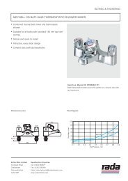
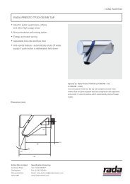
To mains power supplyPSU3 amp switchedfused spur boxDMVOutletMetal pipeworkmust beearth bondedCold inletHot inletControl panelSuppression Ferrite,refer to Note.SpoutNote! The Data Cable must be placed through the Suppression Ferrite and then looped aroundthe cover. The Suppression Ferrite must be fitted as close to the Control Panel as possible.Installation Schematic1. Inlet and outlet isolating valves must be installed close to the DMV for ease ofmaintenance.2. The use of supply-line or zone strainers will reduce the need to remove debris ateach mixing valve point. The recommended maximum mesh aperture dimensionfor such strainers is 0.5 mm.3. Inlet pressure tappings which allow measurement of the inlet pressures tothe mixing valve under operating conditions are particularly recommended forhealthcare applications.4. Pipework must be rigidly supported and avoid any strain on the connections.5. Pipework dead-legs should be kept to a minimum.6. Supply pipework layout should be arranged to minimise the effect of other outletusage upon the dynamic pressures at the mixing valve inlets.7. Inlet and outlet threaded joint connections should be made with PTFE tape orliquid sealant. Do not use oil-based, non-setting joint compounds.8. To eliminate pipe debris it is essential that supply pipes are thoroughly flushedthrough before connection to the spout and to the <strong>Rada</strong> Sense DMV.9. The DMV may only be orientated in the positions shown when mounted on a rigidvertical surface and on top of a rigid horizontal surface in any orientation.7
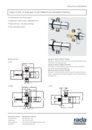
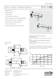
OutletHot inletCold inletMounting on aVertical SurfaceOutletHot inletCold inletOutletHot inletCold inletMounting on aHorizontal SurfaceNote! If the DMV is installed in a different orientation to those shown above, it maycause the DMV to malfunction e.g. cause airlocks, water ingress and could effectthe thermal performance of the DMV.The DMV MUST NOT be installed in the orientations shown below.Cold inletHot inletCold inletHot inletOutletOutlet10. For the installation of your spout, refer to the Sense Spout Kits InstallationManual.POWER SUPPLY UNIT (PSU)Warning! Isolate mains power supply before starting installation. The PSU must beconnected to a 3 amp switched fused spur box.1.5 m cable0.5 m cable3.0 m cableFixing screws (2 off)8
RADA SENSE CONTROL PANELThe <strong>Rada</strong> Sense Control Panel must not be installed in areas where high frequencylighting is used. Certain types of compact fluorescent and low voltage lighting usehigh frequency lamps that can interfere with the infrared system used in the controlpanel. We recommend standard switch-start fluorescent lighting to be installedwithin these areas.Note! If the data cable is installed within a stud partition or recessed into a wall, makesure it is placed within a suitable conduit to allow easy removal during servicing.The Control Panel must only be installed onto a flat wall surface.Template12Caution!Make sure Silicone Sealant is applied in the groove onthe back of the Control Panel to stop water ingress intothe data cable access hole in the finished wall.3Caution!Do not trap the cable.Remove excess sealant.45679
RADA SENSE (DMV)Template123PSU CableConnectionShort CableConnectionfor theControl PanelMoulded Grommet465Note! After installing the PSU andControl Panel cables, if necessary,carefully push the wires between thegrommet and connector to one side.Cable fromthe DMVCable from theControl Panel7OutletCold Inlet8Hot Inlet109
Commissioning must be carried out in accordance with these instructions, andmust be conducted by designated, qualified and competent personnel.Note! For Healthcare Installations, all results must be recorded.1. Restore the water supply and check that there are no leaks.2. Restore the power supply.3. Position your hand over the flow sensor (indicated by a tap) on the control panelto start the DMV, to flush out any air.4. Check the supply temperatures and pressures are within the range statedin SPECIFICATIONS and the guidance information on the prevention oflegionella.5. For Type 2 and 3 installations, check that the designation of the DMV matchesthe application. The supply pressures and temperatures are within the permittedrange for the application.6. Check inlet pipework temperatures for correct function of checkvalvesi.e. the hot water does not cross flow into the cold water supply.7. Check that the temperature(s) and flow rates obtainable are acceptable.8. Carry out a performance check:HealthcareIsolate the cold water supply to the mixing valve and monitor the mixed watertemperature. Record the maximum temperature achieved and the final stabilisedtemperature on restoration of the cold water supply.Note! The final stabilised mixed water temperature should not exceed 46 °C.Any higher temperatures should only occur briefly.CommercialCOMMISSIONINGLocate another outlet on the common cold water supply close to the mixingvalve (operating this outlet should cause a drop in supply pressure), andnote the subsequent effect on blend temperature (should be no more than2 °C change).11
Maximum Temperature SettingThe maximum blend temperature obtainable by the user is limited to preventaccidental selection of a temperature that is too hot.The DMV is fully performance tested and the maximum temperature is factory preset,refer to SPECIFICATIONS.Provided that the installation conditions comply with the operating parameters givenin the specifications section of this manual, the maximum temperature should notrequire adjustment.Should the user require to change the Default, Minimum, Maximum Temperaturesor the Flow Times, refer to your <strong>Rada</strong> Sense Programmer Software Manual.Caution! The outlet temperature must be re-checked after a new temperature hasbeen programmed.Note! The <strong>Rada</strong> Sense Programmer CD supplied, is designed to run onMicrosoft Windows 98/NT/2000/XP operating systems. The programmer softwareis designed to run on Microsoft Pocket PC 2002 and Microsoft Mobile Windows forPocket PC 2003. Refer to your <strong>Rada</strong> Sense Programmer Software Manual.12
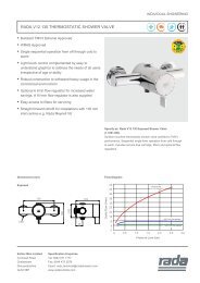
OPERATIONPosition your hand anywhere in front of the control panel to activate the DMV. Wateris delivered at a default temperature, refer to SPECIFICATIONS.Note! The sensors are designed to operate at a distance of up to 30 mm. There isno need for the user to touch the control panel.Position your hand over the Down arrow to obtain a cooler mix. When only the bluelight is illuminated on the control panel, then only cold water is being supplied. If theblue light is flashing, then the minimum preset temperature is being delivered.Position your hand over the Up arrow to obtain a hotter mix.Note! Adjusting the temperature automatically resets the flowtime.The water should flow until either it is switched off manually (by positioning yourhand over the central logo ‘Flow sensor’) or the programmed flow time duration haselapsed.Down arrowLED’s indicatingtemperature selectionUp arrowProgramming windowFlow sensorDuty FlushThe DMV incorporates an option for duty flush which can be selected with the aid ofa Programmer. If duty flush is selected and the DMV is not used for a period of time(pre-set waiting period) the standing water within the DMV will be flushed out.Duty flush temperature, waiting period and flush period are preset at the factory.These settings can be reset, refer to your <strong>Rada</strong> Sense Programmer SoftwareManual.DisinfectionThe DMV incorporates an option for disinfection which can be selected with theaid of a Programmer. The default disinfection settings can be reset, refer to your<strong>Rada</strong> Sense Programmer Software Manual.13
CLEANINGThe <strong>Rada</strong> Sense Control Panel may be temporarily disabled for cleaning purposes.Place the magnetic key (supplied) over the programming window. This will disablethe sensors for 30 minutes or until the magnetic key is reapplied.External surfaces may be wiped clean with a soft cloth, and if necessary, a mildwashing-up type detergent or soap solution can be used.Caution: Plated or plastic fittings should only be cleaned using a mild washing updetergent or soap solution and wiped dry with a soft cloth.14
FAULT DIAGNOSISMaintenance must be conducted by designated, qualified and competentpersonnel.Warning! Isolate power supply and water supply when any maintenance work iscarried out on the DMV.The DMV may contain hot water, so care must be taken when draining the DMV ofany residual water.Caution! The inlet/outlet connections on the DMV, must be held tightly so that theydo not move, when the connections are being loosened or tightened.Symptom1. Control Panel notilluminated.2. Only cold waterfrom outlet.Cause/Rectificationa. Check that you have the correct control panel or DMVfor your application.b. Control panel has been disabled : enable the controlpanel with the magnetic key, refer to CLEANING.c. The mains electricity has been disabled : check andrectify.d. The power supply unit has been disabled : check thefuse and connections.e. Electrical connections to/from the DMV have beendisturbed : make sure the connections are secure.f. Memory requires resetting : switch the power supply tothe electronic mixing valve, OFF and then ON.a. No hot water reaching mixing valve : check andrectify.b. The hot water inlet may be blocked : check strainer forany blockage.c. Installation conditions are outside the operatingparameters : refer to SPECIFICATION.d. Hot and cold feeds connected to the wrong inlets :rectify.3. Continuous flow. a. System switches itself on and off.b. System will not switch off : isolate power supply/water supply and contact your Local Agent/CustomerServices.4. Hot water enteringthe cold supply, orvice versa.a. Remove and clean the checkvalve cartridges. Renewas necessary.15
Symptom5. Fluctuating orreduced flow rate.Normal functionof mixing valvewhen operatingconditions areunsatisfactory.6. Blendtemperature driftor temperaturecycling.7. Maximum blendtemperaturesetting too hot ortoo cool.8. Water leakingfrom the DMV.9. LED’s areflashing on thecontrol panel andthe DMV will notactivate.10. The DMV keepsswitching OFFbefore thecompletion of theprogrammed timeflow period.Cause/Rectificationa. The inlet/outlet fittings may be restricted : check the inlet/outlet strainers, refer to PLANNED MAINTENANCE.b. The water outlet pressure is low : check the flow rate isabove the stated minimum, refer to SPECIFICATION.c. Fluctuating flow : make sure that dynamic inlet pressuresare within specification, refer to SPECIFICATION.d. Fluctuating water temperature : make sure thatinlet temperature differentials are sufficient, refer toSPECIFICATION.a. Refer to symptoms 4 and 5.b. Hot water supply temperature fluctuation : check andrectify.a. Incorrect maximum temperature setting : refer toCOMMISSIONING.Warning! Isolate mains electricity and water supply.a. Check that the connections are secure.b. Seal(s) worn or damaged on the inlet/outletconnections : obtain service pack and renew allseals.c. Internal leakage : unit requires overhaul.a. An error has been diagnosed, refer to Self-diagnosticErrors (following table).a. Blend temperature too hot : Reset the DMV by switchingthe power supply to the DMV OFF, then ON.b. Make sure that the inlet temperatures are withinspecification, refer to SPECIFICATION.If the fault has not been rectified, contact your Local Agentor Customer Care.16
Self-diagnostic ErrorsError code is displayed by a combination of lit LED’sAll three LED’s flash at the same timeSymptomorCause/RectificationThe Control Panel and the DMV are not compatible.a. DMV W or B requires CP W: check and rectify.If the symptom has not been rectified, contact yourLocal Service Engineer or Agent.Outlet Temperature is too high or Thermistor fault.a. The inlet/outlet fittings may be blocked: check the inlet/outlet strainersb. Cold water supply failure: reinstate supplyc. Safety circuit may require resetting: enable the controlpanel with the magnetic key to reset.If the symptom has not been rectified, contact yourLocal Service Engineer or Agent.Thermistor fault.a. Contact your Local Service Engineer or Agent.The Stepper Motor is stuck, the motor belt is broken or theMixer assembly is jammed.a. Contact your Local Service Engineer or Agent.The Mixer assembly is jammed or very stiff.a. Contact your Local Service Engineer or Agent.Any othercombinations.A fault has occurred on the Control PCB.a. Memory may require resetting: switch the power supplyto the PSU, OFF then ON.If the symptom has not been rectified, contact yourLocal Service Engineer or Agent.17
PLANNED MAINTENANCEMalfunction of the DMV is almost always progressive in nature and will be detectedby the use of proper temperature checking and maintenance routines.Certain types of system can result in the DMV having excessive ‘dead-legs’ ofpipework, or auxiliary cold water supply added to the mixed water from the mixingvalve. Such systems can disguise the onset of thermostatic mixing valve malfunctionand should not be used.We recommend a preventative maintenance procedure based on site conditionsand the risk to the user. All results must be recorded in a log book.HealthcareHealthcare applications are hospitals, aged person facilities, residential care homes,etc. and any other applications where the user is similarly at risk.Ultimately, the user or attendant must exercise diligence to make sure that the deliveryof warm water is at a stable, safe temperature. This is particularly important in suchprocedures as supervised bathing where patients are unable to respond immediatelyto unsafe temperatures.Irrespective of supply and usage conditions or the evidence of in-service tests, thecritical components listed in the table below, should be replaced at intervals of nomore than 5 years.Note! During the replacement of critical components, it may be necessary to replaceother non-critical components.Pack NumberCritical ComponentsDescription463.31 DMV Solenoid manifold (Open)463.07 Thermistor pack18
Frequency of In-service TestsHealthcareFollow the procedure detailed in the flow diagram “In-service Test Procedure”. Thisprocedure must be followed 6 to 8 weeks after commissioning and 12 to 15 weeksafter commissioning. The recorded blend temperature (Tb) from these two tests willdetermine the maximum frequency for future service intervals.Result of 6-8 week tests Result of 12-15 week tests Next service interval< 1 °C < 1 °C 9 - 12 weeks> 1 °C < 1 °C 9 - 12 weeks< 1 °C > 1 °C 9 - 12 weeks> 1 °C > 1 °C 6 - 9 weeksThe subsequent in-service test results should be used as a guide, in conjunction witha suitable risk assessment, to determine the schedule of future in-service tests.More regular temperature checks should be made where increased risks areperceived, i.e. patients are unable to immediately respond to an increase in watertemperature, by either shutting the water off or removing themselves from contactwith the water.Maintenance personnel should also make sure that the staff are aware of theimportance of reporting temperature variations and when detected, these shouldbe recorded in the Log Book.CommercialCheck for correct blend setting every 6 months.Follow the procedure detailed in the flow diagram “In-service Test Procedure”,every 12 months.19
StartMeasure and record supply temperatures,pressures and make sure that they are withinthe valve specification.Measure and record blend temperature (Tb)and flow rate.Hasflow rate fallensignificantly or fallen belowminimum flowspecification?NoYesCheck and clean checkvalves,strainers and outlets.Measure and record blendtemperature (Tb) and flow rate.YesHasflow rate improved?NoCarry out a Performance Check.Refer to the Commissioning Procedure.Hasblend temperaturechanged by more than2 °C from previousrecorded value (Tb)?NoYesRefer to Fault DiagnosisCarry out theCommissioning Procedure.FinishNote! All measurements and results should be recorded in the Log Book.Flow diagramIn-service Test Procedure20
Checkvalves and FiltersWarning! The DMV may contain hot water, so care must be taken when draining thevalve of any residual water. Isolate the supplies to the DMV and operate the controlpanel to release pressure and to assist the draining of residual water.Note! The DMV have checkvalve and filter packs (cartridge assemblies) orcheckvalves and strainers fitted. These components can be removed for cleaning.Inlet strainers can be flushed through under a jet of water to remove any lodgedparticles.Caution! The checkvalves are not serviceable items, so any apparent wear ordamage will require their renewal.Note! Make sure all components are clean before refitting the ‘O’ seals. To assist inrefitting, lightly wipe the ‘O’ seals with a silicone‐only based lubricant.12CheckvalveInlet strainerInlet adapterCartridgeassembliesInlet adapter3 4CheckvalveInlet strainerInlet adapterCartridgeassembliesInlet adapter5Restore the hot and cold water supplies. Check that there are no water leaks.21
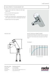
A463.93463.03AA463.04463.28A464.01463.07AA463.28463.26464.04A463.27AA463.31A463.13463.25463.28A464.03463.21463.28463.80463.06463.84463.82463.76463.77463.83463.79464.2922
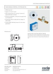
Note! If fixing screws, grommets, ‘O’ rings or seals are disturbed, these parts willbe included with the spare part.463.03 C6 Valve Assembly - Includes Stepper Motor, Stepper Loom,Checkvalve and Filter Pack, Inlet Saddle Clamps and Thermistor Clip463.04 Stepper Motor Assembly - Includes Timing Belt463.05 Seal Screw Pack - Components Identified ‘A’463.06 Cable Cover Pack463.07 Twin Thermistor Pack463.13 Inlet Adapter 3/4 BSP - x2 Adapters and Inlet Saddle Clamps463.21 Outlet Adapter 3/4 BSP - x1 Adapter and Outlet Saddle Clamps463.25 Checkvalve Cartridge Assembly463.26 Blanking Plate Pack463.27 Damping Chamber463.28 Internal Saddle Clamp463.31 Solenoid Manifold (Open)Includes Manifold Cap and Internal Saddle Clamps463.76 <strong>Rada</strong> Sense Bath Control Panel463.77 <strong>Rada</strong> Sense Control Panel Cover 3 Sens (Chrome)463.80 Control PCB RADA C6 Bath - Programmed with Bath Software463.82 <strong>Rada</strong> Sense Programmer CD T3463.83 12 V DC 45 W Power Supply Unit (PSU)463.84 <strong>Rada</strong> Sense Disable Key - x4463.93 Stepper Motor Loom464.01 Wiring Loom RADA T464.03 Outlet Saddle Clamp464.04 Inlet Saddle Clamp464.29 Suppression Ferrite463.79 Extension Lead - 3 mSpoutsSPARE PARTSACCESSORIES<strong>Rada</strong> has a comprehensive range of spouts and shower fittings,available separately.23
CUSTOMER CAREGuarantee of QualityKohler Mira Ltd. guarantee this product against any defect in materials or workmanship for the period of fi veyears from the date of purchase, covering all parts, labour for the fi rst year and replacement parts only for thenext four years.To be covered by this guarantee, service work must only be undertaken by Kohler Mira Ltd. or by their approvedagents. Service labour will be free of charge for the fi rst year and chargeable at prevailing rates for the next fouryears.Not covered by this guaranteeDamage or defects arising from incorrect installation, improper use or failure to maintain in accordance with theinstructions in this product manual, including the build-up of limescale. Defects or damage if the product is takenapart, repaired or modifi ed by a person not authorised by Kohler Mira Limited or by their approved agents.After Sales Service - how we can help youWe have a network of fully trained staff ready to provide assistance, should you experience any diffi cultyoperating your <strong>Rada</strong> equipment.Spare PartsAll functional parts of <strong>Rada</strong> products are kept for up to ten years from the date of fi nal manufacture. If during thatperiod, our stock of a particular part is exhausted we will, as an alternative, provide an equivalent new productor part at a price equating to the cost of repair to the old, bearing in mind the age of the product.All spares are guaranteed for 12 months from date of purchase. Spares that have been supplied directly fromus can be returned within one month from date of purchase, providing that they are in good order and thepackaging is unopened.Note! Returned spares will be subject to a 15% restocking charge and authorisation must be obtained beforereturning any spare part.Customer Care PolicyIf within a short space of time of installation the product does not function correctly, fi rst check with the operationand maintenance advice provided in this Product Manual to see if the diffi culty can be overcome. Failing this,contact your installer to make sure that the product has been installed and commissioned in full accord with ourdetailed installation instructions. If this does not resolve the diffi culty, please ring your nearest <strong>Rada</strong> contact,who will give you every assistance and if appropriate, arrange for your local service engineer or agent to callon a mutually agreeable date.Contact:For the latest information on <strong>Rada</strong> sense, visit www.radasense.com<strong>Rada</strong> ControlsCromwell Road, Cheltenham, GL52 5EP,England, UKTelephone: +44 (0)870 600 0221Fax: +44 (0)1242 221925SPECIFICATION ENQUIRIESTelephone: +44 (0)1242 282527Fax: +44 (0)1242 282404E-mail: rada_technical@mirashowers.com<strong>Rada</strong> is a registered trade mark ofKohler Mira Limited.The company reserves the right to alterproduct specifi cations without notice.www.radacontrols.com241095146_W2_A (N73A) © Kohler Mira Limited, January 2008