flame detector for gas type re3 - System Control Engineering
flame detector for gas type re3 - System Control Engineering
flame detector for gas type re3 - System Control Engineering

You also want an ePaper? Increase the reach of your titles
YUMPU automatically turns print PDFs into web optimized ePapers that Google loves.
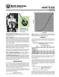
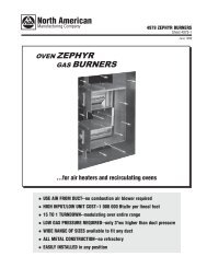
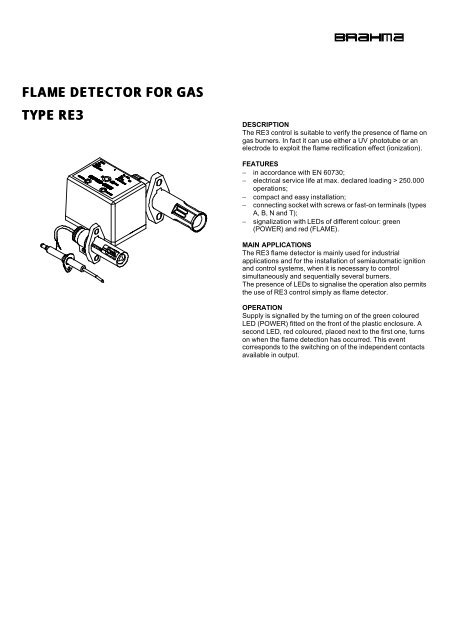
FLAME DETECTOR FOR GASTYPE RE3DESCRIPTIONThe RE3 control is suitable to verify the presence of <strong>flame</strong> on<strong>gas</strong> burners. In fact it can use either a UV phototube or anelectrode to exploit the <strong>flame</strong> rectification effect (ionization).FEATURES− in accordance with EN 60730;− electrical service life at max. declared loading > 250.000operations;− compact and easy installation;− connecting socket with screws or fast-on terminals (<strong>type</strong>sA, B, N and T);− signalization with LEDs of different colour: green(POWER) and red (FLAME).MAIN APPLICATIONSThe RE3 <strong>flame</strong> <strong>detector</strong> is mainly used <strong>for</strong> industrialapplications and <strong>for</strong> the installation of semiautomatic ignitionand control systems, when it is necessary to controlsimultaneously and sequentially several burners.The presence of LEDs to signalise the operation also permitsthe use of RE3 control simply as <strong>flame</strong> <strong>detector</strong>.OPERATIONSupply is signalled by the turning on of the green colouredLED (POWER) fitted on the front of the plastic enclosure. Asecond LED, red coloured, placed next to the first one, turnson when the <strong>flame</strong> detection has occurred. This eventcorresponds to the switching on of the independent contactsavailable in output.
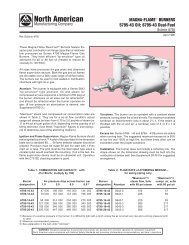
OVERALL DIMENSIONSCable length:mm 600 (standard)(*) It depends on the socket <strong>type</strong>:59.5 socket A63.5 socket B62.8 socket N and TFig.2socket A and B(*) It depends on the socket <strong>type</strong>:5 socket A9 socket Bsocket TFig.3The phototube UV2/N has an intermediate sensitivity betweenstandard and selected UV1.As regards the phototube life, we suggest to replace it after10.000 hours to avoid the danger of a “<strong>flame</strong> on” signal alsoafter the <strong>flame</strong> has been extinguished, which is likely tohappen when the tube gets too old.DETECTION ELECTRODEThe detection electrode we produce can be supplied indifferent shapes and dimensions.socket NFig.1This control can use the connecting sockets with screwterminals mod. A, B, N or socket mod. T. <strong>for</strong> fast - onterminals, which couples with lateral bolted enclosure.Please note that socket <strong>type</strong> B is higher than <strong>type</strong> A and itsterminals can hold a greater number ofcables.ACCESSORIESThe users’ different requirements regarding <strong>flame</strong> detection<strong>for</strong> <strong>gas</strong> systems, can be met by using the following probes ofour production:- UV1 standard phototube (Fig.2);- UV1/A selected phototube;- UV1/H high sensitivity phototube:Case:nylonCase diameter: mm 22Case length: mm 85Cable length:mm 600 (standard)- UV2/N (Fig.3):Case:nylonCase diameter: mm 17Case length: mm 76Fig.4TECHNICAL DATA- Supply: 220V-50/60Hzon request: 240V-50/60Hz110V-50/60Hz- Operating temperature: 0 ÷ 60°C- Humidity: 95% max. at 40°C- Case Protection Degree: IP40- Power consumption in running: 3 VA- Contact rating: 5A 250 V AC ( cosϕ = 1.0)3A 250 V AC ( cosϕ = 0.4)5A 30 V DC- External Fuse (F): 50 mA T- Minimum ionization current: 1µA- Recommended ionization current:with UV tube: > 15µAwith electrode: > 5µA- Reaction time: < 1s
(a)
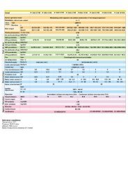
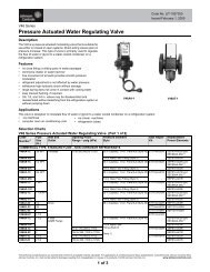
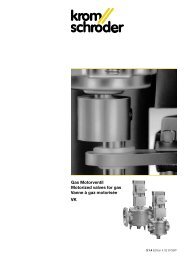
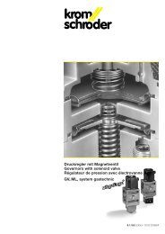
Fig.8 represents two connection diagrams <strong>for</strong> using the RE3<strong>flame</strong> <strong>detector</strong> with the control box <strong>for</strong> automatic <strong>gas</strong> burners,model CM391 belonging to the EUROBOX series (see therelevant leaflet).The diagram in Fig.8a differs from the one in Fig.8b <strong>for</strong> thepresence of fan control and air pressure switch. Thisconnection permits the ignition of two burners in sequence,with cross checking of the “<strong>flame</strong> on” state. A contact of theinternal relay of RE3 is used to check the efficiency of the<strong>detector</strong> to prevent the beginning of the ignition cycle if the<strong>detector</strong> doesn’t operate correctly.The ignition of burner 2 occurs only after the ignition of burner1 and, as the <strong>flame</strong> detection is cross - checked betweenCM391 and RE3, the turning off of one burner causes also theimmediate turning off of the other one.(b)BRAHMA S.p.A.Via del Pontiere, 3137045 Legnago (VR)Tel. +39 0442 635211 - Telefax +39 0442 25683 - 635256 Subject to amendments without notice 02/96E-mail : export@brahma.it