
Create successful ePaper yourself
Turn your PDF publications into a flip-book with our unique Google optimized e-Paper software.
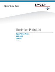
Spicer ® Steer Axles<strong>Illustrated</strong> <strong>Parts</strong> <strong>List</strong>AXIP0090November 2005I FamilyD Family
IntroductionIntroductionAbout this <strong>Parts</strong> BookThis Spicer parts book is presented as an aid in the identificationand procurement of replacement parts for Spicer steer axles. Theinformation included covers the most commonly used parts.<strong>Parts</strong> have been grouped by category such as beams and centers,knuckles and cross rods; however, Spicer recommends using kits.Whether you are using kits or individual parts, the model serviced isprominently identified in each group.This book covers I and D axles separately; determine your axle typeand work from the appropriate table of contents.AbbreviationsA/R-As Required: <strong>Parts</strong> that vary in quantity with each axle.Example: shims.NSS-Not Serviced Separately: Items which can only be purchasedin sets, kit form, or service assemblies.Genuine Spicer <strong>Parts</strong>When you buy genuine Spicer replacement parts, you receive thesame high quality and exacting tolerances you find in the originalsteer axle components.Only genuine Spicer parts have the latest Spicer engineeringimprovements and assure equal or better performance than theoriginal parts.And Spicer backs you up with a responsive and capable serviceorganization strategically located to provide you with emergencyparts and service when you need them.Insist on Spicer quality. Use genuine Spicer replacement parts.Ordering Spicer <strong>Parts</strong>Place all you parts orders through your truck dealer or manufacturer(OEM). Do not order parts directly from Spicer.Spicer <strong>Parts</strong> KitsSpicer <strong>Parts</strong> Kits give you an economical, convenient way to stockSpicer replacement parts. They contain all the parts you need to doa complete, professional job of overhauling or repairing your Spicersteer axle. And you have only one part number in one easily storedpackage to order, stock, identify, and satisfy your customer’s needs.2
IdentificationIdentificationThe Spicer front non-drive steering axles are identified with a taglocated between the spring pads, on the front side of the centerbeam section.The axle tag contains the serial number, the model number, and theassembly number.The Spicer model numbering system provides pertinent informationabout the axle for easy identification.Axle Assembly TagModel Identification Numbering SystemSeriesI(GAWR x 45 kg [100 lbs])I - 200 WBeam TypeSG = I-Beam Standard Overall WidthSB = Coach BeamW = Over 244 cm [96 in.] Overall WidthFutureDesign LevelD - 85 0 FTagSeriesD(GAWR x 450 kg [1000 lbs])Design Level0 = Standard AxleBeam TypeF = I-Beam Standard Overall WidthW = Over 2438 mm (96 in.) Overall WidthSpicer PartNumberSerialNumberCustomerPart Number(Optional)JulianDate CodeModelLine Set Number(Optional)3
IdentificationModel CoverageI FamilySpicer Steer Axle Model No.I60I80I00S, WI120S, SG, SGL, WI132SGI140S, WI160S, WI180S, WI200S, WI220WD FamilyNominal Ratings6,000 lbs.8,000 lbs.10,000 lbs.12,000 lbs.13,200 lbs.14,000 lbs.16,000 lbs.18,000 lbs.20,000 lbs.22,800 lbs.Note:Model NumberD-600ND-700ND-700FD800FD800WD850FD850WD2000FD2000F (5” Drop)D2200FAxle Capacity6,000 lbs. [2,722 kg]{7,000 lbs. [3175 kg]8000 lbs. [3,629 kg]8500 lbs. [3,856 kg]20,000 lbs. [9,072 kg]22,800 lbs. [10,342 kg]These nominal ratings are general guidelines. Actual loadrating varies with application and duty cycle. Applicationsrequire Spicer engineering approval.5
I Family Steer Axle ComponentsI Family Steer Axle ComponentsI-60 and I-80 <strong>Parts</strong> Explode156283A10129111741314BItem Description Shown onA I-Beam 15B Kingpin Kits 23C Knuckle Assy 21D Stop Bolt Assy 25E Steering Arm 24F Tie Rod Arm 19G Tie Rod Assy 26C171918D1521E1612 G1120891015F6
I Family Steer Axle ComponentsI-60 and I-80 <strong>Parts</strong> <strong>List</strong>Item Part Name Qty. I-60, I-80 Remarks1* Seal, King Pin OilUpper 2 101HH101Lower 2 101HH1012* Shim.005" Thick A/R HS111.010" Thick A/R HS1123* Draw Key, Outer 21.505" Taper Length A/R HP119-31.630" Taper Length A/R HP119-21.755" Taper Length A/R HP119-51.880" Taper Length A/R HP119-11.880" Taper Length A/R HP119-44* Draw Key, Inner 2 071HP1015* Nut, Draw Key 2 220HN1036* Washer, Belleville 4 1460HN100 Replaces 220HN1027* Bearing Assembly, Thrust 2 080HC1008 Bolt, King Pin Cap 8 HM241 Replaces 101HM1019* Grease Fitting 4 819790 Replaces HN14410 Cap, King Pin 4 085SC101 Replaces 071SC10211* O-Ring 4 HH10312* Bushing, King Pin 4 101HD10113 Pin, Cotter 3 220HP101 Length: 2.2514 Nut, Slotted 2 HN14615 Key, Woodruff 3 HP10316 Pin, Cotter 2 HP102 Length: 1.7517 Pin, Cotter 2 HP118 Length: 1.5018 Washer, Bearing Retainer 2 HN16719 Nut, Spindle 2 HN14720 Lock, Spindle Nut 2 HN16821 Sleeve, ABS Mounting (ABS Only) 2 120RT100*Item included in Kingpin kit. Refer to P. 23 for kit information.7
I Family Steer Axle ComponentsI-100, I-120, I-132 and I-140 <strong>Parts</strong> Explode1238A10967541211113BItem Description Shown onA I-Beam 15B Kingpin Kits 23C Knuckle Assy 21D Stop Bolt Assy 25E Steering Arm 24F Tie Rod Arm 19G Tie Rod Assy 2614C171918D1521E16G1520F8
I Family Steer Axle ComponentsI-100W, I-120W and I-140W <strong>Parts</strong> Explode21310118917654A1213BItem Description Shown onA I-Beam 15B Kingpin Kits 23C Knuckle Assy 21D Stop Bolt Assy 25E Steering Arm 24F Tie Rod Arm 19G Tie Rod Assy 2614C171918D15E2016G15F10
I Family Steer Axle ComponentsI-100W, I-120W and I-140W <strong>Parts</strong> <strong>List</strong>Item Part Name Qty. I-100W - I-140W Remarks1* Seal, King Pin Oil Upper 2 160HH100Lower 2 160HH1002* Shim .005" Thick A/R 160HS100-1.010"Thick A/R 160HS100-2.020" Thick A/R 160HS100-33* Draw Key, Outer 2 071HP1014* Draw Key, Inner 2 160HP102-35* Nut, Draw Key 4 220HN1036* Washer, Belleville 8 1460HN100 Replaces 220HN1027* Bearing Assembly, Thrust 2 220HC1008 Bolt, King Pin Cap 12 HM2419* Grease Fitting 2 819790 Replaces HN14510 Cap, King Pin 4 120SC105 Replaces 120SC10411* O-Ring 4 220HH10212* Bushing, King Pin 4 160HD10213 Pin, Cotter 4 220HP101 Length: 2.2514 Nut, Slotted (Grade 8) 4 161HN10115 Key, Woodruff 3 HP10316 Pin, Cotter 2 HP102 Length: 1.7517 Pin, Cotter 2 HP115 Length: 2.2518 Washer, Bearing Retainer 2 140HN10319 Nut, Spindle 2 140HN10420 Lock, Spindle Nut 2 140HN10521 Sleeve, ABS Mounting (ABS Only) 2 120RT100*Item included in Kingpin kit. Refer to P. 23 for kit information.11
I Family Steer Axle ComponentsI-160, I-180, and I-200 <strong>Parts</strong> Explode21310118917654A1213BItem Description Shown onA I-Beam 15B Kingpin Kits 23C Knuckle Assy 21D Stop Bolt Assy 25E Steering Arm 24F Tie Rod Arm 19G Tie Rod Assy 2614C171918D15E2016G15F12
I Family Steer Axle ComponentsI-160, I-180 and I-200 <strong>Parts</strong> <strong>List</strong>Item Part Name Qty. I-160 I-180 I-200 Remarks1* Seal, King Pin Oil Upper 2 160HH100 160HH100 160HH100Lower 2 160HH100 160HH100 160HH1002* Shim .005" Thick A/R 160HS100-1 160HS100-1 160HS100-1.010" Thick A/R 160HS100-2 160HS100-2 160HS100-2.020" Thick A/R 160HS100-3 160HS100-3 160HS100-33* Draw Key, Outer 3.38" Length 2 220HP100-1 220HP100-1 220HP100-13.08" Length 2 071HP101 071HP101 071HP1014* Draw Key, Inner 4.62" Length 2 220HP100-2 220HP100-2 220HP100-23.56" Length 2 160HP102-2 160HP102-2 160HP102-25* Nut, Draw Key 4 220HN103 220HN103 220HN1036* Washer, Belleville 8 1460HN100 1460HN100 1460HN100 Replaces 220HN1027* Bearing Assembly, Thrust 2 220HC100 220HC100 220HC1008 Bolt, King Pin Cap 12 HM241 HM241 HM2419* Grease Fitting 4 819790 819790 819790 Replaces HN14510 Cap, King Pin 4 220SC111 220SC111 220SC111 Replaces 220SC10211* O-Ring 4 220HH103 220HH103 220HH10312* Bushing, King Pin 4 160HD102 160HD102 160HD10213 Pin, Cotter 3 220HP101 220HP101 220HP101 Length: 2.2514 Nut, Slotted 2 161HN101 161HN101 161HN10115 Key, Woodruff 3 HP103 HP103 HP10316 Pin, Cotter 2 HP102 HP102 HP102 Length: 1.7517 Pin, Cotter 2 HP116 HP116 HP116 Length: 3.0018 Washer, Bearing Retainer 2 220HN105 220HN105 220HN10519 Nut, Slotted 2 220HN104 220HN104 220HN10420 Sleeve, ABS Mounting (ABS Only) 2 120RT100 120RT100 120RT100*Item included in Kingpin kit. Refer to P. 23 for kit information.13
I Family Steer Axle ComponentsI-160W, I-180W, I-200W and I-220W <strong>Parts</strong> Explode21310118917654A1213BItem Description Shown onA I-Beam 15B Kingpin Kits 23C Knuckle Assy 21D Stop Bolt Assy 25E Steering Arm 24F Tie Rod Arm 19G Tie Rod Assy 2614C171918D15E2016G15F14
I Family Steer Axle ComponentsI-160W, I-180W, I-200W and I-220W <strong>Parts</strong> <strong>List</strong>Item Part Name Qty. I-160W I-180W - I-220W Remarks1* Seal, King Pin Oil Upper 2 160HH100 160HH100Lower 2 160HH100 160HH1002* Shim .005" Thick A/R 160HS100-1 160HS100-1.010" Thick A/R 160HS100-2 160HS100-2.020" Thick A/R 160HS100-3 160HS100-33* Draw Key, Outer 3.38" Length 2 220HP100-13.13" Length 2 220HP100-34* Draw Key, Inner 4.62" Length 2 220HP100-2 220HP100-25* Nut, Draw Key 4 220HN103 220HN1036* Washer, Belleville 8 1460HN100 1460HN100 Replaces 220HN1027* Bearing Assembly, Thrust 2 220HC100 220HC1008 Bolt, King Pin Cap 12 HM241 HM2419* Grease Fitting (90°) 2 819790 819790 Replaces HN14510 Cap, King Pin 4 220SC111 220SC111 Replaces 220SC10211* O-Ring 4 220HH103 220HH10312* Bushing, King Pin 4 160HD102 160HD10213 Pin, Cotter 4 220HP101 220HP10114 Nut, Slotted 4 161HN101 161HN10115 Key, Woodruff 4 HP103 HP10316 Pin, Cotter 2 HP102 HP10217 Pin, Cotter HP116 HP11618 Washer, Bearing Retainer 2 220HN105 220HN10519 Nut, Slotted 2 220HN104 220HN10420 Sleeve, ABS Mounting (ABS Only) 2 120RT100 120RT100*Item included in Kingpin kit. Refer to P. 23 for kit information.15
I Family I-BeamsI Family I-Beams“DØ”“B”“C”King Pin Bore Ø“A”“FØ”“E”(Depth)I-60 and I-80 I-BeamsKing Pin Bore Ø A B C D Ø E F Ø Spicer Part Number Remarks1.360 31.00 3.656 4.25 .781 .625 .656 080TB114-233.00 3.689 3.70 .812 .625 .689 080TB106-435.00 3.656 4.25 .656 .625 .656 080TB106-1080TB114-13.689 3.70 .812 .625 .689 080TB106-5I-100, I-120, I-132 and I-140 I-BeamsKing Pin Bore Ø A B C D Ø E F Ø Spicer Part Number Remarks1.360 31.00 3.656 4.25 .781 .625 .656 080TB114-21.862 32.50 4.812 4.25 .812 .630 .812 140TB115-134.00 3.780 4.25 .812 .625 .781 100TB102-1140TB106-14.812 4.25 .812 .625 .781 140TB106-3100TB102-335.00 4.812 4.25 .812 .625 .781 100TB102-241.06 3.780 4.25 .812 .625 .781 140TB106-21.923 32.00 4.812 4.25 .812 .620 .781 100TB101-9 Replaces 100TB101-332.50 4.812 4.25 .812 .630 .812 140TB120-9 Replaces 140TB104-1233.00 4.812 4.25 .812 .690 .812 140TB120-7 Replaces 140TB104-1033.50 4.312 4.25 .812 .690 .910 140TB121-14 Replaces 140TB108-1734.00 3.780 4.25 .812 .625 .781 140TB121-12 Replaces 140TB108-154.812 4.25 .812 .620 .781 100TB101-10 Replaces 100TB101-4.625 .781 140TB121-13 Replaces 140TB108-1635.00 3.780 4.25 .812 .620 .781 100TB101-8 Replaces 100TB101-24.812 4.25 .812 .620 .781 140TB102-6 Replaces 140TB102-1100TB101-7 Replaces 100TB101-116
I Family I-BeamsI-100, I-120, I-132 and I-140 I-Beams (continued)King Pin Bore Ø A B C D Ø E F Ø Spicer Part Number Remarks2.048 31.00 3.812 4.25 .812 .625 .812 140TB121-10 Replaces 140TB108-1332.00 3.780 4.25 .812 .625 .781 140TB121-3 Replaces 140TB108-33.812 4.25 .812 .750 .781 140TB121-9 Replaces 140TB108-12140TB120-6 Replaces 140TB104-94.940 4.25 .812 .620 .940 140TB120-3 Replaces 140TB104-45.060 4.38 .812 .620 1.062 140TB120-5 Replaces 140TB104-832.50 4.312 4.25 .812 .690 .812 140TB121-11 Replaces 140TB108-144.940 4.25 1.062 .937 .937 140TB121-7 Replaces 140TB108-1034.00 3.780 4.25 .812 .625 .781 140TB116-1140TB121-5 Replaces 140TB108-74.812 4.25 .812 .620 .781 140TB102-9 Replaces 140TB102-5.625 .781 140TB121-8 Replaces140TB108-11140TB116-3.780 .812 140TB120-8 140TB104-1135.00 4.812 4.25 .812 .620 .781 140TB102-7 Replaces 140TB102-2140TB120-2 Replaces 140TB104-2140TB104-13.625 .781 140TB121-2 Replaces 140TB108-2140TB108-194.940 4.25 .812 .620 .940 140TB104-6140TB104-14.625 .937 140TB108-636.06 3.780 4.25 .812 .625 .781 140TB121-6 Replaces 140TB108-841.06 3.780 4.25 .812 .625 .781 140TB116-2I-160, I-180 and I-200 I-BeamsKing Pin Bore Ø A B C D Ø E F Ø Spicer Part Number Remarks1.862 32.00 3.812 4.25 .812 .750 .781 140TB113-133.00 4.812 4.25 .812 .690 .812 140TB113-234.00 4.812 4.25 .812 .780 .812 140TB113-32.048 31.00 3.940 4.25 .812 .625 .940 220TB101-14 Replaces 220TB101-832.00 5.062 4.38 .812 .690 1.062 220TB101-11 Replaces 220TB101-25.00 .812 .690 1.062 220TB101-10 Replaces 220TB101-132.50 4.312 4.25 .812 .690 .812 220TB101-13 Replaces 220TB101-734.00 3.000 4.25 .505 .500 .781 140TB105-23.790 4.25 .505 .500 .781 140TB105-135.00 5.062 5.00 .812 .690 1.062 220TB101-12 Replaces 220TB101-640.00 3.000 4.25 .505 .500 .781 161TB101-240.95 5.118 5.00 .505 .500 .750 161TB108-117
I Family I-BeamsI-100W, I-120W and I-140W I-BeamsKing Pin Bore Ø A B C D Ø E F Ø Spicer Part Number Remarks2.048 33.00 4.810 4.25 .810 .620 .780 140TB119-1I-160W I-BeamsKing Pin Bore Ø A B C D Ø E F Ø Spicer Part Number Remarks2.048 33.00 5.062 5.00 .810 .690 1.060 160TB104-1I-180W, I-200W and I-220W I-BeamsKing Pin Bore Ø A B C D Ø E F Ø Spicer Part Number Remarks2.048 33.00 5.062 5.00 .810 .690 1.060 220TB104-118
I Family Tie Rod ArmsI Family Tie Rod ArmsI-60 - I-200 Tie Rod Arms“B”“C” L“A”A B Thread Spicer Part Number-1.05 6.88 LH 080TR105RH 080TR106-.18 5.72 LH 080TR107RH 080TR108.17 6.41 LH 120TR103-5RH 120TR104-5.44 4.88 LH 080TR102RH 080TR104LH 080TR133-1RH 080TR134-1.77 5.66 LH 120TR103-6RH 120TR104-61.37 4.91 LH 120TR103-4RH 120TR104-4.09 14.61 RH 161TR108LH 161TR107.17 6.41 LH 120TR103-2RH 120TR104-2.29 5.94 LH 120TR136-6RH 120TR138-6-.31 6.69 LH 120TR136-5RH 120TR138-5.47 6.47 LH 120TR114-1RH 120TR115-1.63 5.94 LH 120TR136-2RH 120TR138-2.73 6.22 LH 120TR114-4RH 120TR115-4.77 5.66 LH 120TR103-3RH 120TR104-3.80 8.61 LH 161TR103-2RH 161TR104-2.89 5.19 LH 120TR136-7RH 120TR138-71.10 5.55 LH 220TR112RH 220TR1131.24 5.44 LH 120TR136-1RH 120TR138-11.37 4.91 LH 120TR103-1RH 120TR104-11.42 4.53 LH 220TR108RH 220TR1091.61 5.37 LH 120TR142-1RH 120TR144-1Note:Negative value in column "A" indicates that hole lies onopposite side of centerline.19
I Family Tie Rod Arms“C” LI-100W, I-120W and I-140W Tie Rod ArmsA B Thread Spicer Part Number1.74 5.47 LH 140TR139-1RH 140TR140-11.58 5.47 LH 140TR139-2RH 140TR140-21.40 5.72 LH 140TR139-3RH 140TR140-31.12 5.97 LH 140TR139-4RH 140TR140-40.65 6.72 LH 140TR139-5RH 140TR140-50.47 6.72 LH 140TR139-6RH 140TR140-6“B”I-160W, I-180W, I-200W and I-220WTie Rod Arms“A”A B Thread Spicer Part Number1.78 5.12 LH 220TR135-1RH 220TR136-11.20 5.72 LH 220TR135-2RH 220TR136-20.81 5.89 LH 220TR135-3RH 220TR136-31.59 6.02 LH 220TR135-4RH 220TR136-41.02 6.41 LH 220TR135-5RH 220TR136-50.50 6.87 LH 220TR135-6RH 220TR136-620
I Family KnucklesI Family KnucklesI-60 through I-200 and I-100W through I-220W KnucklesABSPosition(L2)L.H."D"Pilot Dia.(mm)R.H."C" Steering StopPosition"A"TaperDirection"B"TaperDirectionKing PinBore (Ø)Service PartNo.Note: Viewed from front of spindleKnuckle Part No.(NSS)KnuckleSideA B C DABSLocationRemarks1.36 101SK111-X 101SK109 RH Shown Shown RH 5.000 See Remarks 9 hole bolt pattern; ABS positionis middle left.101SK112-X 101SK110 LH Opposite Opposite LH 5.000 See Remarks 9 hole bolt pattern; ABS positionis middle right.1.48 061SK100-1X 061SK101 LH Shown Shown RH 5.000 NA061SK102-1X 061SK103 RH None Opposite LH 5.000 NA101SK100-1X 101SK102 LH Shown Shown RH 5.000 NA101SK103-1X 101SK104 RH None Opposite LH 5.000 NA1.86 140SK102-X 140SK100 LH Shown Shown RH 5.495 NA140SK103-X 140SK101 RH Opposite Opposite LH 5.495 NA1.99 140SK106-X 140SK104 LH Shown Shown RH 5.495 L1 Knotched140SK107-X 140SK105 RH Opposite Opposite LH 5.495 R1 Knotched2.04 120SK115-X 120SK111 LH Shown Shown RH 5.495 L2 Knotched120SK116-X 120SK112 RH Opposite Opposite LH 5.495 R2 Knotched120SK129-X 120SK127 LH Shown Shown RH 5.495 L2 Knotched120SK130-X 120SK128 RH None Shown LH 5.495 R2 Knotched120SK159-X 120SK157 LH Shown Shown RH 5.495 L1 Knotched120SK160-X 120SK158 RH None Shown LH 5.495 R1 Knotched120SK155-X 120SK153 LH Shown Shown RH 5.495 L1 Knotched120SK156-X 120SK154 RH Opposite Opposite LH 5.495 R1 Knotched120SK102-X 120SK100 LH Shown Shown RH 5.495 NA120SK103-X 120SK101 RH Opposite Opposite LH 5.495 NA120SK145-X 120SK143 LH Shown Shown RH 5.495 NA120SK146-X 120SK144 RH None Opposite LH 5.495 NA21
I Family KnucklesKing PinBore (Ø)Service PartNo.Knuckle Part No.(NSS)KnuckleSideA B C DABSLocationRemarks2.17 160SK125-X 160SK123 LH Shown Shown RH 5.495 L1 Knotched160SK126-X 160SK124 RH Opposite Opposite LH 5.495 R1 Knotched160SK103-X 160SK101 LH Shown Shown RH 5.495 NA Knotched160SK104-X 160SK102 RH Opposite Opposite LH 5.495 NA Knotched160SK117-X 160SK113 LH Shown Shown RH 5.495 L2 Knotched160SK118-X 160SK114 RH Opposite Opposite LH 5.495 R2 Knotched161SK102-X 161SK100 LH Shown Shown RH 5.745 NA161SK103-X 161SK101 RH Opposite Opposite LH 5.745 NA161SK106-X 161SK104 LH Shown Shown RH 5.745 NA161SK107-X 161SK105 RH None Opposite LH 5.745 NA Contains special threaded upperboss holes161SK110-X 161SK108 LH Shown Shown RH 5.745 L2161SK111-X 161SK109 RH Opposite Opposite LH 5.745 R2220SK103-X 220SK101 LH Shown Shown RH 5.745 NA220SK104-X 220SK102 RH Opposite Opposite LH 5.745 NA220SK111-X 220SK109 LH Shown Shown RH 5.745 L2220SK112-X 220SK110 RH Opposite Opposite LH 5.745 R2Identifying Steer Knuckle Taper Directions: In identifying tapered directions for steer knuckles, Columns A & B indicate the tapered direction of each knuckle as laid outexactly as pictured above. It doesn’t matter if the knuckle is a LH or RH knuckle, lay the knuckle out as shown above and identify the taper direction. The taper directionsare identified as “shown” for the tapers illustrated above or “opposite” for tapers in the opposite direction of the illustration above.22
I & D Family Kingpin KitsI & D Family Kingpin Kits2198123410116571Kit Part No.ModelKingpin PartNo. (NSS)All Kits include items 1-11 illustrated above except where noted.KingpinLengthBushingTypeKingpinDesignRemarks101KK110 I-80 101SC100 7.79 x 1.36 Garlock A101KK111 I-80101SC101 8.07 X 1.35 Garlock CD-800F/W (Made before 9/18/02)101KK113 I-80 441241C1 7.79 X 1.35 Bronze A309KK102 I-90 441111C2 9.16 x 1.609 Synthetic C Replaces 309KK100309KK103 I-90 441111C2 9.16 x 1.609 Bronze C120KK100 I-100SA, I-100S/SG, I-120S/SG 120SC100 9.87 x 1.92 Garlock C220KK100 I-100S/SG, I-120S/SG, I-140S/SG 220SC108 10.94 x 2.05 Garlock C Knuckle 220SC100 replaced by 220SC108120KK102 I-120SA, I-140SA, I-146SA 140SC100 10.77 x 1.86 Garlock C140KK100 I-132SG, I-140S/SG 160SC100 10.12 x 2.05 Garlock C329022 I-140W 160SC100 10.12 x 2.05 Garlock C151KK101 I-160S, I-180S 220SC108 10.94 x 2.05 Garlock C161KK100 I-160S 161SC100 11.00 x 2.05 Garlock C For MCI Bus329023 I-160W 220SC108 10.94 x 2.05 Garlock C329116 I-161 161SC101 11.00x1.79 Garlock C For Neoplan Bus329070 I-180W, I-200W, I-220W 220SC108 10.94 x 2.05 Garlock C329182 D-600N/F, D-700ND-800F/W (Made after 9/18/02)D-850 F/W085SC100 8.07 X 1.35 Garlock B331434 D-2000F, D-2200F 220SC110 10.06x2.04 Garlock C Use with 5” drop assembly. Kit includesitems 1-8 & 10-12.331435 D-2000F, D-2200F 220SC112 10.06x2.04 Garock B Use with 3.5” drop assembly. Kit includesitems 1-8 & 10-12.ABCKingpin Design23
I Family Steer ArmsI Family Steer ArmsI-60 through I-200 and I-100W through I-220W“C”“B”Up“A”DownDirection A B C (Ø) Thread Spicer Part Number RemarksDown 7.52 1.58 .938 140SA102140SA102-21.044 140SA102-4140SA131-1140SA131-28.42 1.53 .938 LH 140SA104-11.044 LH 140SA104-28.47 1.09 .727 101SA101.753 101SA101-17.52 1.58 .938 140SA141-17.24 1.53 .938 140SA148-26.59 1.53 .938 140SA148-36.966 .14 1.044 RH 220SA115-18.58 .19 .938 LH 220SA121-17.36 .74 .938 LH 220SA121-27.966 .392 1.044 LH 220SA113-18.56 .19 .938 RH 220SA123-17.34 .64 .938 RH 220SA123-224
I Family Stop BoltsI Family Stop Bolts“D”“A”“B”“C”1 2 3Model Style Turn Angle (Max.) A B C D Assembly Part NumberI-60, I-80 1 50° NA 500380-5 NSS 1.50" 101HM110-1XNSS 1.75” 101HM110-3XNSS 2.25” 101HM110-2XI-100 thru I-140 2 50° 160HN100-1 NA NSS 2.63" 140HM100-1XI-100 thru I-120 3 50° 120HN100 HN148 NSS 2.25" 120HM101I-100 thru I-140 2 50° 160HN100-1 NA NSS 3.00" 140HM100-3X160HN100-1 NA NSS 2.38" 140HM100-4XI-160 thru I-200 1 45° NA 220HN106 NSS 2.38" 220HM102-1X2 45° 220HN100-2 NA NSS 2.38” 220HM102-2X1 45° NA 220HN106 NSS 2.00" 220HM102-3XI-100W thru I-140W 2 50° 160HN100-1 NA NSS 2.38" 140HM100-4X2 45° 160HN100-1 NA NSS 2.63" 140HM100-1XI-160W thru I-220W 1 50° NA 220HN106 NSS 2.50" 220HM102-5X2 43° 220HN100-2 NA NSS 2.75" 220HM102-4XNSS - Not Sold Separately25
I Family Tie Rod Assemblies/KitsI Family Tie Rod Assemblies/Kits“A”“A”“B”“B”* Drop-Center ApplicationI-80 & I-100 Tie Rod AssembliesTIE ROD END ASSY - COMPLETE CROSS TUBES TIE ROD ENDSI-80 I-100Assy.Length“A”CrossTubeWidthCross TubeAssy.(includesclamp)TubeLength“B”LH Side Type RH SideNA 120TR100-1X 64.72 1.50 120TR106 59.38 120TR109 S 120TR110NA 100TR105-3X 64.72 1.44 NA 59.38 140TR111 S 140TR112NA 220TR114-1* 65.62 2.50 220TR120 48.20 220TR118 D 220TR119NA 120TR100-2X 65.92 1.50 120TR107 60.56 120TR109 S 120TR110NA 100TR105-4X 65.92 1.44 100TR109 60.56 140TR111 S 140TR112NA 220TR100-3 66.24 1.75 220TR117-3 61.00 220TR115 S 220TR116NA 100TR111-1X 67.12 1.44 100TR112 67.12 140TR111 S 140TR112080TR109-3 NA 68.64 1.44 080TR115 50.32 080TR116 D 080TR117D = Drop Socket Design S = Straight DesignI-120, I-130, I-132 & I-140 Tie Rod AssembliesTIE ROD END ASSY - COMPLETE CROSS TUBES TIE ROD ENDSI-120I-130I-132I-140Assy.Length“A”CrossTubeWidthCross TubeAssy.(includesclamp)TubeLength“B”LH Side Type RH SideNA 140TR129-1* 64.72 2.25 140TR116-1 43.25 140TR130 D 140TR131NA 140TR105-2 65.28 1.62 140TR118 51.79 140TR111 S 140TR112220TR114-1* 220TR114-1* 65.62 2.50 220TR120 48.20 220TR118 D 220TR119NA 120TR100-2X 65.92 1.50 120TR107 60.56 120TR109 S 120TR110NA 140TR100-2X 65.92 1.62 140TR107 60.56 140TR109 S 140TR110NA 140TR129-2 65.92 2.25 NA 43.38 140TR130 D 140TR131220TR100-3 220TR100-3 66.24 1.75 220TR117-3 61.00 220TR115 S 220TR116NA 815326 66.90 1.75 NA 60.00 817018 S 817019120TR123-3* NA 67.12 2.00 120TR122-2 43.38 140TR114 D 140TR115NA 140TR105-1 67.12 1.62 140TR108 53.63 140TR111 S 140TR112120TR130-2 NA 67.96 1.50 120TR134 62.60 140TR109 S 140TR110NA 971443 68.90 1.66 971444 62.00 817018 S 817019D = Drop Socket Design S = Straight Design26
I Family Tie Rod Assemblies/KitsI-Family Tie Rod Assemblies/Kits(Cont.)“A”“A”“B”“B”* Drop-Center ApplicationI-160, I-180 & I-200 Tie Rod AssembliesI-160TIE ROD END ASSY - COMPLETE CROSS TUBES TIE ROD ENDSI-180I-200Assy.Length“A”CrossTubeWidthCross TubeAssy.(includesclamp)TubeLength“B”LH Side Type RH Side161TR100-3 NA 70.03 1.75 161TR114-3 64.79 220TR115 S 220TR116NA 220TR100-3 66.24 1.75 220TR117-3 61.00 220TR115 S 220TR116D = Drop Socket Design S = Straight DesignI-100W through I-220W Tie Rod AssembliesI-100WI-120WI-140WTIE ROD END ASSY - COMPLETE CROSS TUBES TIE ROD ENDSI-160WI-180WI-200WI-220WAssy.Length “A”CrossTubeWidthCross TubeAssy.(includesclamp)TubeLength“B”LH Side Type RH Side971092 NA 68.50 1.90 971093 61.00 818472 S 818471NA 220TR129-1 66.50-71.00 1.90 220TR132-1 61.00 220TR130 S 220TR131D = Drop Socket Design S = Straight Design27
D Family Steer Axle ComponentsD-600N and D-700N <strong>Parts</strong> Explode78Item Description Shown onA I-Beam 34B Kingpin Kits 23C Knuckle Assy 36D Stop Bolt Assy 36E Steering Arm 38F Tie Rod Arm 35G Tie Rod Assy 3712109111452A13316D61415EC1918 17BGF28
D Family Steer Axle ComponentsD-600N & D-700N <strong>Parts</strong> <strong>List</strong>77Item Part Name Qty.D-600ND-700N1 King Pin Oil Seal Upper 2 101HH101Lower 2 101HH1012* Shim .005” Thick A/R HS111.010” Thick A/R HS1123* Draw Key, Inner 4 071HP1014* Nut, Draw Key 4 220HN1035* Washer, Belleville 8 1460HN1006* Bearing Assembly, Thrust 2 080HC1007* Grease Fitting 2 819790 Replaces HN1448 Bolt, King Pin Cap 8 HM2419 Cap, King Pin 4 085SC101 Replaces 071SC10210* O-Ring 4 HH10311* Bushing, King Pin 4 101HD10112 Pin, Cotter 3 220HP10113 Nut, Slotted 3 HN14614 Key, Woodruff 2 HP10315 Pin, Cotter 2 HP10216 Pin, Cotter 2 HP11817 Washer, Bearing Retainter 2 HN16718 Nut, Spindle 2 HN14719 Lock, Spindle Nut 2 HN168*Item included in Kingpin kit. Refer to P. 23 for kit information.Notes29
D Family Steer Axle ComponentsD-700F, D-800F/W and D-850F/W <strong>Parts</strong> ExplodeD-800 before October 1, 20028313910B6541112561142C17720191821D16G154ABFEGItem Description Shown onA I-Beam 34B Kingpin Kits 23C Knuckle Assy 36D Stop Bolt Assy 36E Steering Arm 38F Tie Rod Arm 35G Tie Rod Assy 3730
D Family Steer Axle ComponentsD-700F, D-800F/W and D850F/W <strong>Parts</strong> <strong>List</strong>Item Part Name Qty.D-700FD-800F/WD-850F/WRemarks1* Seal, King Pin OilUpper 2 101HH101 101HH101Lower 2 101HH101 101HH1012* Shim.005” Thick A/R HS111 HS111.010” Thick A/R HS112 HS1123* Draw Key, Outer 2 080HP100 N/A4* Draw Key, Inner 2 071HP101 N/ADraw Key, Inner 4 N/A 07HP1015* Nut, Draw Key 4 220HN103 220HN1036* Washer, Belleville 8 220HN102 220HN1027* Bearing Assembly, Thrust 2 080HC100 080HC1008 Bolt, King Pin Cap 8 HM241 HM2419* Grease Fitting 4 819790 819790 Replaces HN14410 Cap, King Pin 4 085SC101 085SC101 Replaces 071SC10211* O-Ring 4 HH103 HH10312* Bushing, King Pin 4 101HD101 101HD10113 Cotter Pin 3 220HP101 220HP10114 Nut, Slotted 3 HN146 HN14615 Key, Woodruff 3 HP103 HP10316 Cotter Pin 2 HP102 HP10217 Cotter Pin 2 HP118 HP11818 Washer 2 HN167 HN16719 Nut, Spindle 2 HN147 HN14720 Lock, Spindle Nut 2 HN168 HN16821 Sleeve, ABS Mounting (ABS Only) 2 120RT100 120RT100*Item included in Kingpin kit. Refer to P. 23 for kit information.** For models with Julian dates through October 1, 2002, use D-800F part numbers. Julian dates after October 1, 2002, useD-850F part numbers.31
D Family Steer Axle ComponentsD-2000F and D-2200F <strong>Parts</strong> Explode15" Drop Beam Configuration23A176541D8562910A12C1174313F161715221418E212019BItem Description Shown onA I-Beam (3.5" Drop) 34B Kingpin Kits 23C Knuckle Assy 36D Steering Arm 38E Tie Rod Arm 35F Tie Rod Assy 3732
D Family Steer Axle ComponentsD-2000F and D-2200F <strong>Parts</strong> <strong>List</strong>Item Part Name Qty.D-2000FD-2200F1* Seal, King Pin OilUpper 2 160HH100Lower 2 160HH1002* Shim.005” Thick A/R 160HS100-1.010” Thick A/R 160HS100-2.020” Thick A/R 160HS100-33* Draw Key, Inner 2 220HP100-14* Draw Key, Inner 2 220HP100-25* Nut, Draw Key 4 220HN1036* Washer, Belleville 8 1460HN1007* Bearing Assembly, Thrust 2 220HC1008* Grease Fitting 4 10014149 Cap, King Pin 4 97137010* Foam Insert 4 97101011* Bushing, King Pin 4 160HD10012 Cotter Pin 4 220HP10113 Nut, Slotted 4 161HN10114 Key, Woodruff 4 HP10315 Cotter Pin 2 HP10216 Screw, Stop 2 97145417 Nut, Hex 2 220HN10618 Washer 2 220HN10519 Locknut, Hex Flange 2 97692120 Washer - Keyed 2 HN11421 Lock, Spindle Nut 2 M10HN10722 Sleeve, ABS Mounting (ABS Only) 2 120RT100*Item included in Kingpin kit. Refer to P. 23 for kit information.Remarks33
D Family Steer Axle ComponentsD Family I-Beams“DØ”“B”“C”King Pin Bore Ø“A”“FØ”“E”(Depth)D600N, D-700N/F, D-800F, D-850F, D-2000F and D-2200F I-BeamsKing PinBore (Ø)A B C D Ø E F Ø Spicer Part Number Beam Drop1.360 32.00 3.812 4.250 0.810 0.625 0.810 085TB100-1*1.360 32.50 4.810 4.250 0.810 0.625 0.690 085TB100-61.360 35.00 3.812 4.250 0.810 0.625 0.810 072TB101-1 3.5”2.048 34.00 4.940 4.250 0.812 0.780 0.940 220TB101-19 5”2.048 34.00 4.940 4.250 0.812 0.780 0.940 220TB108-2*Before October 1, 2002 Time Frame Axles, need King Pin Kit with Beam.D-800W and D-850W I-BeamsKing PinBore (Ø)A B C D Ø E F Ø Spicer Part Number Remarks1.360 32.00 3.812 4.250 0.810 0.625 0.810 085TB100-21.360 33.00 4.680 4.580 0.780 0.625 0.810 085TB100-5*Before October 1, 2002 Time Frame Axles, need King Pin Kit with Beam.34
D Family Steer Axle Components“B”“C” L“A”D Family Tie Rod ArmsD600N, D700N/F, D-800F/W, D-850F/W,D-2000F and D-2200F Tie Rod ArmsA B Thread Spicer Part Number0.830 4.93 LH 081TR108-30.160 4.93 RH 081TR109-30.830 5.06 LH 081TR108-40.160 5.06 RH 081TR109-40.370 5.00 LH 081TR108-50.370 5.00 RH 081TR109-50.640 4.93 LH 081TR108-60.160 5.06 RH 081TR109-41.47 6.01 LH 220TR145-11.47 6.01 RH 220TR146-1.90 6.40 LH 220TR145-2.90 6.40 RH 220TR146-2.38 6.86 LH 220TR145-3.38 6.86 RH 220TR146-31.66 5.11 LH 220TR145-41.66 5.11 RH 220TR146-41.08 5.71 LH 220TR145-51.08 5.71 RH 220TR146-5.69 5.88 LH 220TR145-6.69 5.88 RH 220TR146-635
D Family Steer Axle ComponentsD Family KnucklesABSPosition(L2)L.H."D"Pilot Dia.(mm)R.H."C" Steering StopPosition"A"TaperDirection"B"TaperDirectionD-600N, D-700N/F, D-800F/W, D-850F/W, D-2000F and D-2200F KnucklesKing PinBore (Ø)Service PartNo.D Family Stop BoltsKnuckle PartNo. (NSS)KnuckleSideA B C DABSLocation1.48 072SK103 072SK101 LH Shown Shown RH 4.125 NA 6 hole bolt pattern1.48 072SK104 072SK102 RH None Shown LH 4.125 NA 6 hole bolt pattern1.48 085SK103 085SK101-1 LH Shown Shown RH 5.000 SeeRemarks1.48 085SK104 085SK102-1 RH None Opposite LH 5.000 SeeRemarks1.48 085SK105 085SK101-2 LH Shown Shown RH 5.000 SeeRemarks1.48 085SK106 085SK102-2 RH None Shown LH 5.000 SeeRemarksRemarks9 hole bollt pattern; ABS position ismiddle left.9 hole bollt pattern; ABS position ismiddle right.9 hole bollt pattern; ABS position ismiddle left.9 hole bollt pattern; ABS position ismiddle right.2.17 220SK138-1 220SK136-1 LH Opposite Opposite RH 5.745 L2 8 hole bolt pattern2.17 220SK139-1 220SK137-1 RH Opposite Opposite LH 5.745 R2 8 hole bolt pattern2.17 220SK138-2 220SK136-2 LH Opposite Shown RH 5.745 L2 8 hole bolt pattern2.17 220SK139-2 220SK137-2 RH Shown Opposite LH 5.745 R2 8 hole bolt patternIdentifying Steer Knuckle Taper Directions: In identifying tapered directions for steer knuckles, Columns A & B indicate the tapered direction of each knuckle as laid outexactly as pictured above. It doesn’t matter if the knuckle is a LH or RH knuckle, lay the knuckle out as shown above and identify the taper direction. The taper directionsare identified as “shown” for the tapers illustrated above or “opposite” for tapers in the opposite direction of the illustration above.CNote: Viewed from front of spindleABD-600N/F, D-700N, D-800F/W and D-850F/W Stop BoltsModelTurn Angle(Max.)A B CAssembly PartNumberD-600N, D-700N/F 45-55° 500380-5 NSS 1.75 101HM110-3XD-800F/W, D-850F/W 50° 500380-5 NSS 2.25" 101HM110-2XNSS - Not Sold Separately36
D Family Steer Axle ComponentsD Family Tie Rod Assemblies / Kits“A”“A”“B”“B”* Drop-Center ApplicationD-600N, D-700N/F, D-800F/W, D-850F/W, D-2000F and D-2200F Tie Rod Assemblies/KitsModel Tie Rod Assy Tie Rod Socket ThreadsD-600ND-700ND-600FD-800F/WD-850F/WD-2000D-2200FTube andClamp Assy971814 8117018 LH NA 62.00” 55.00”8117019 RH971314 8117018 LH NA 71.10" 63.50"8117019 RH971762 970579 LH NA 67.60" 56.00"970580 RHA B Remarks220TR114-1 220TR118 LH 220TR120 65.62 48.20 Use with 5” drop assembly220TR119 RH220TR129-2 220TR130 LH NA 63.00 - 67.50 57.50 Use with 3.5” drop assembly220TR131 RH37
D Family Steer Axle ComponentsD Family Steer Arms“C”“B”Up“A”DownD-600N, D-700N/F, D-800F/W, D-850F/W, D-2000F and D-2200F Steer ArmsDirection A B C (Ø) Spicer Part Number RemarksDown 7.380 1.91 .938 081SA101-27.380 1.15 .938 081SA101-17.270 2.07 .938 081SA101-3Up 8.715 1.392 1.044 220SA140-18.715 1.392 1.044 220SA142-1Down 8.715 1.392 1.220 220SA144-18.715 1.392 1.220 220SA146-138
For spec‘ing or service assistance, call 1-877-777-5360 or visit our website at www.dana.comDana Commercial Vehicle Products Group3939 Technology DriveMaumee, Ohio, USA 43537www.dana.comAll applications must be approved by the Application Engineering Department. Specifications and/or design are subject to change without notice or obligation. Printed in USA AXIP-0090 11/05