Review of Radiation Therapy Physics: A syllabus for teachers ... - IRSN
Review of Radiation Therapy Physics: A syllabus for teachers ... - IRSN
Review of Radiation Therapy Physics: A syllabus for teachers ... - IRSN
You also want an ePaper? Increase the reach of your titles
YUMPU automatically turns print PDFs into web optimized ePapers that Google loves.
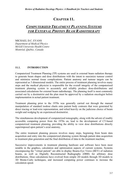
<strong>Review</strong> <strong>of</strong> <strong>Radiation</strong> Oncology <strong>Physics</strong>: A Handbook <strong>for</strong> Teachers and StudentsCHAPTER 11.COMPUTERIZED TREATMENT PLANNING SYSTEMSFOR EXTERNAL PHOTON BEAM RADIOTHERAPYMICHAEL D.C. EVANSDepartment <strong>of</strong> Medical <strong>Physics</strong>McGill University Health CentreMontréal, Québec, Canada11.1. INTRODUCTIONComputerized Treatment Planning (TP) systems are used in external beam radiation therapyto generate beam shapes and dose distributions with the intent to maximize tumour controland minimize normal tissue complications. Patient anatomy and tumour targets can berepresented as 3 dimensional models. The entire process <strong>of</strong> treatment planning involves manysteps and the medical physicist is responsible <strong>for</strong> the overall integrity <strong>of</strong> the computerizedtreatment planning system to accurately and reliably produce dose-distributions andassociated calculations <strong>for</strong> external beam radiotherapy. The planning itself is most commonlycarried out by a dosimetrist and the plan must be approved by a radiation oncologist be<strong>for</strong>eimplementation in actual patient treatment.Treatment planning prior to the 1970s was generally carried out through the manualmanipulation <strong>of</strong> standard isodose charts onto patient body contours that were generated bydirect tracing or lead-wire representation, and relied heavily on the judicious choice <strong>of</strong> beamweight and wedging by an experienced dosimetrist.The simultaneous development <strong>of</strong> computerized tomography, along with the advent <strong>of</strong> readilyaccessible computing power from the 1970s on, lead to the development <strong>of</strong> CT-basedcomputerized treatment planning, providing the ability to view dose distributions directlysuperimposed upon patient’s axial anatomy.The entire treatment planning process involves many steps, beginning from beam dataacquisition and entry into the computerized planning system through patient data acquisitionto treatment plan generation and the final distribution <strong>of</strong> data to the treatment machine.Successive improvements in treatment planning hardware and s<strong>of</strong>tware have been mostnotable in the graphics, calculation and optimization aspects <strong>of</strong> current systems. Systemsencompassing the “virtual patient” are able to display Beams-Eye Views (BEV) <strong>of</strong> radiationbeams, as well as Digitally Reconstructed Radiographs (DRR) <strong>for</strong> arbitrary dosedistributions. Dose calculations have evolved from simple 2D models through 3D models to3D Monte-Carlo techniques, and increased computing power continues to increase thecalculation speed.317
Chapter 11. Computerized Treatment Planning Systems <strong>for</strong> External Beam radiotherapyTraditional “<strong>for</strong>ward-based” treatment planning which is based on a trial and error approachby experienced pr<strong>of</strong>essionals is giving way to “inverse planning” which make use <strong>of</strong> doseoptimization techniques to satisfy user specified criteria <strong>for</strong> the dose to the target and criticalstructures. Dose optimization is possible by making use <strong>of</strong> Dose-Volume Histograms (DVH)based on CT, MR or other digital imaging techniques. These optimized plans make use <strong>of</strong>Intensity Modulated <strong>Radiation</strong> <strong>Therapy</strong> (IMRT) to deliver a required dose to a target organwhile respecting dose constraint criteria <strong>for</strong> critical organs.Computerized treatment planning is a rapidly evolving modality, relying heavily on bothhardware and s<strong>of</strong>tware. As such it is necessary <strong>for</strong> related pr<strong>of</strong>essionals to develop aworkable Quality Assurance (QA) programme that reflects the use <strong>of</strong> the TP system in theclinic, and is sufficiently broad in scope to ensure proper treatment delivery.11.2. SYSTEM HARDWARE11.2.1. TP system hardwareThe principal hardware components <strong>of</strong> a TP system include: CPU, graphics display, memory,digitizing devices, output devices, archiving and network communication devices. Ashardware capabilities tend to change quickly, the general approach is to acquire equipmenthaving the highest current specifications while allowing <strong>for</strong> future upgrades.• The Central Processing Unit (CPU) must have sufficient memory and processorspeed as required by the operating system, and the treatment planning s<strong>of</strong>tware. Inparticular the specifications <strong>for</strong> the system speed, Random Access Memory(RAM) and free memory, as well as networking capabilities must be considered.• The graphics display is normally sufficient <strong>for</strong> accommodating the patienttransverse anatomy on a 1:1 scale, typically 17 to 21 inches (43 to 53 cm) orlarger. The resolution is sub-millimeter or better so as not to distort the input.Graphics speed can be enhanced with video cards and hardware drivers.• Memory and archiving functions are carried out either through removable mediaor networking. Removable media may include floppy disks, re-writable harddisks,optical disks, or DVDs. Mass archiving may also be accomplished withslower DAT tape, however, these devices have been reported to suffer from longterm instability. Archiving may be carried out over a network on a remotecomputer or server, and these archiving operations may be carried outautomatically during low use periods <strong>of</strong> the day. Archiving operations can includebeam data and parameters, patient related data such as CT-scans and dosedistributions, and data used <strong>for</strong> setting up the patient <strong>for</strong> treatment on the linacwith record-and-verify systems.• Digitizing devices are used to acquire manually entered patient data such astransverse contours and beams-eye-views <strong>of</strong> irregular field shapes. These aretypically backlit tablets with either a magnetic or acoustic stylus <strong>for</strong> manuallytracing shapes. Scanners, either flatbed or upright, can be used to digitize imagesfrom hardcopy such as paper or radiographic film. Video frame grabbers may alsobe used to digitize images.318
<strong>Review</strong> <strong>of</strong> <strong>Radiation</strong> Oncology <strong>Physics</strong>: A Handbook <strong>for</strong> Teachers and Students• Output devices include color laser printers and plotters <strong>for</strong> text and graphics.Printers and plotters can be networked <strong>for</strong> shared access. Hardcopy can be topaper or to film via a laser camera.• Uninterruptable Power Supplies (UPS) are recommended <strong>for</strong> the CPU, dataservers, and other critical devices such as those used <strong>for</strong> storage and archiving.UPSs can provide back-up power so that a proper shut-down <strong>of</strong> the computer canbe accomplished during power failures from the regular power distribution grid,and they also act as surge suppressors <strong>for</strong> the power.• Communications hardware includes modem or ethernet cards on the localworkstations and multiple hubs <strong>for</strong> linking various peripheral devices andworkstations. Large networks require fast switches running at least 100 Mb/s <strong>for</strong>file transfer associated with images. Physical connections on both small and largenetworks are run through coaxial cable, twisted pair or optical fiber dependingupon speed requirements.• Environmental conditions under which the TP system hardware runs may besubject to temperature and humidity requirements. Thus the physical location <strong>of</strong>the equipment associated with the TP system within a department is <strong>of</strong>importance.11.2.2. TP system configurations• Smaller TP system configurations may have a stand-alone lay-out whereby onecentral CPU handles most functions and communication requests. In thisconfiguration there may be only a few users, and access to peripheral devicesused <strong>for</strong> printing and archiving is not shared. Network requirements may also belimited, however, even stand-alone TP systems now routinely require networkswitches to communicate with digital imaging devices such as CT-scanners.• Larger systems <strong>of</strong>ten operate within a hospital-wide network, and may also makeuse <strong>of</strong> Internet-based communication systems. Many <strong>of</strong> the devices operated andaccessed by the large TP system configuration will not have a direct connection,and must be accessed through a number <strong>of</strong> network switches using acommunications protocol such as TCP/IP. These larger systems may also have aremote server <strong>for</strong> various file handling tasks related to patient data, digital images,beam data, and dose calculation. Large area TP system configurations havingmany users and remote workstations may require the services <strong>of</strong> an administratorto maintain security, user rights, networking, back-up and archiving.11.3. SYSTEM SOFTWARE AND CALCULATION ALGORITHMSDose calculation algorithms are the most critical s<strong>of</strong>tware component in the computerized TPsystem. These modules are responsible <strong>for</strong> the correct representation <strong>of</strong> dose in the patient,and may be linked to beam-time or monitor unit (MU) calculations. Dose calculations haveevolved from simple 2 dimensional calculations, to partial 3 dimensional point kernelmethods, to full 3 dimensional dose models in which the histories <strong>of</strong> the primary and scatteredradiation in the volume-<strong>of</strong>-interest are considered.319
Chapter 11. Computerized Treatment Planning Systems <strong>for</strong> External Beam radiotherapy11.3.1. Calculation algorithms••••There are numerous dose calculation algorithms used by computerized treatmentplanning systems, and due to the rapidly changing nature <strong>of</strong> computer power theimplementation <strong>of</strong> these techniques is a constantly evolving process. Specificdetails on treatment planning dose algorithms can be found throughout theliterature, and a small selection is included in the reference section <strong>of</strong> this chapter.Prior to understanding sophisticated computerized treatment planning algorithms,a proper understanding <strong>of</strong> manual dose calculations is essential, and there aremany texts which adequately discuss these methods, including Johns andCunningham, Khan, and Hendee and Ibbot among others.The ICRU Report 42 lists the chronological development <strong>of</strong> dose calculationalgorithms <strong>for</strong> photon and electron beams. It provides representative examples <strong>for</strong>the calculation <strong>of</strong> central axis depth dose and cross beam or <strong>of</strong>f-axis ratios <strong>for</strong>photon beams. Representative examples <strong>for</strong> electron beam calculations includingempirical and semi-empirical <strong>for</strong>malism <strong>for</strong> the calculation <strong>of</strong> central axis depthdose and empirical <strong>for</strong>malism <strong>for</strong> the calculation <strong>of</strong> cross beam or <strong>of</strong>f-axis ratiosare also provided.Early TP system generated dose distributions through the manipulation <strong>of</strong>relatively simple 2D beam data <strong>for</strong> a range <strong>of</strong> square fields in water. These datasets comprised matrices <strong>of</strong> central-axis (CAX) percent depth-dose (PDD) andseveral <strong>of</strong>f-axis ratios (pr<strong>of</strong>iles) at a number <strong>of</strong> depths.• To speed up the calculation, CAX data was converted and stored as “infinitePPD” data, while the pr<strong>of</strong>iles were stored along ray-lines back-projected to anarbitrary SSD. In this manner, data could be rapidly manipulated using look-uptables to generate dose distributions onto external patient contours. These types<strong>of</strong> algorithms were used <strong>for</strong> both photon and electron beam treatment planningand lead to very fast dose calculations. However, in general they were not trulyrepresentative <strong>of</strong> the 3D scattering conditions in the patient.••Prior to the advent <strong>of</strong> widespread CT use in treatment planning, irregular fielddosimetry was accomplished using Beams-Eye View films <strong>of</strong> treatment fieldsobtained with conventional simulators. Using the CAX and pr<strong>of</strong>ile data sets, theprimary and scatter components <strong>of</strong> the beam could be separated using the zeroarea Tissue-Air-Ratio and Scatter-Air-Ratio at depth to generate Clarkson sectorintegration calculations <strong>for</strong> points-<strong>of</strong>-interest in the irregular field.The approach <strong>of</strong> current beam calculation algorithms is to decompose theradiation beam into primary and secondary or scatter components, and to handleeach component independently. In this manner, changes in scattering due tochanges in the beam shape, beam intensity, patient geometry and tissue inhomogeneitiescan be incorporated into the dose distribution.320
<strong>Review</strong> <strong>of</strong> <strong>Radiation</strong> Oncology <strong>Physics</strong>: A Handbook <strong>for</strong> Teachers and Students••One such model uses convolution methods whereby the dose at any point in themedium can be expressed as the sum <strong>of</strong> the primary and scatter components.These models use superposition principles to account <strong>for</strong> both local changes in theprimary fluence as well as changes in the spread <strong>of</strong> energy due to local scatteringcaused by patient and beam geometry. Under specific conditions <strong>of</strong> non-divergentsources and homogeneous phantoms, convolution type integrals can be used tosimplify and speed up these calculations.Monte Carlo or random sampling techniques are used to generate dosedistributions by following the histories <strong>of</strong> a large number <strong>of</strong> particles as theyemerge from the source <strong>of</strong> radiation and undergo multiple scattering interactionsboth inside and outside the patient.• Monte Carlo techniques are able to accurately model the physics <strong>of</strong> particleinteractions by accounting <strong>for</strong> the geometry <strong>of</strong> individual linear accelerators,beam shaping devices such as blocks and multileaf collimators (MLCs), andpatient surface and density irregularities. They allow a wide range <strong>of</strong> complexpatient treatment conditions to be considered. In order to achieve a statisticallyacceptable result, Monte Carlo techniques require the simulation <strong>of</strong> a largenumber <strong>of</strong> particle histories, and are only now becoming practical <strong>for</strong> routinetreatment planning as computing power reduces the calculation time to anacceptable level on the order <strong>of</strong> a few minutes <strong>for</strong> a given treatment plan.••Pencil beam algorithms are common <strong>for</strong> electron beam dose calculations. In thesetechniques the energy spread or dose kernel at a point is summed along a line inphantom to obtain a pencil-type beam or dose distribution. By integrating thepencil beam over the patient’s surface to account <strong>for</strong> the changes in primaryintensity and by modifying the shape <strong>of</strong> the pencil beam with depth and tissuedensity, a dose distribution can be generated.As pointed out by Cunningham, treatment planning algorithms have progressedchronologically to include analytical, matrix, semi-empirical and threedimensionalintegration methods.- The analytical technique as developed by Sterling calculated the dose in themedium as the product <strong>of</strong> two equations, one <strong>of</strong> which modeled the percentdepth dose, the other modeled the beam’s <strong>of</strong>f-axis component. The modelhas been extended to incorporate field shielding and wedge hardening.- Treatment planning computer systems developed in the 1970s began usingthe diverging matrix method <strong>of</strong> beam generation based on measured data.- The Milan-Bentley model was used to calculate diverging fan-lines thatradiate from a source and intersect depth lines located at selected distancesbelow the patient surface. Dose distributions are made by rapidlymanipulating measured data sets consisting <strong>of</strong> central axis percent depthdose and <strong>of</strong>f-axis ratio data sets stored as a function <strong>of</strong> field size. Thesetechniques continue to be used in treatment planning algorithms (Storchiand Woudstra), although they suffer from the perceived disadvantage <strong>of</strong>requiring large amounts <strong>of</strong> measured data, and their limited ability toproperly model scatter and electron transport conditions.321
Chapter 11. Computerized Treatment Planning Systems <strong>for</strong> External Beam radiotherapy- Semi-empirical dose calculation methods model the dose to a point byconsidering the contribution from the primary and scattered radiationindependently. Based originally on the Clarkson scatter integrationtechnique, these models have been refined by combining the <strong>for</strong>malism <strong>of</strong>basic physics with data derived from measurement. Correction factors toaccount <strong>for</strong> penumbra, block transmission and flattening filters haveimproved on these models.- These methods have been further refined by applying differential scatter-airratio techniques to allow <strong>for</strong> variations in the intensity <strong>of</strong> scatter radiationthroughout the field due to the presence <strong>of</strong> wedges or non-uni<strong>for</strong>m surfacecontours.- Three-dimensional integration methods represent the transport <strong>of</strong> electronsand photons away from the primary site <strong>of</strong> interaction so as to have anaccurate description <strong>of</strong> the deposition <strong>of</strong> absorbed energy while consideringthe geometry and composition <strong>of</strong> the entire volume being irradiated. MonteCarlo techniques <strong>for</strong> computing dose spread arrays or kernels used inconvolution-superposition methods are described by numerous authorsincluding Mackie and the review chapters in Khan and Potish, and Van Dykprovide a detailed summary <strong>of</strong> treatment planning algorithms in general.11.3.2. Beam modifiersTreatment planning s<strong>of</strong>tware <strong>for</strong> photon beams as well as electron beams must be capable <strong>of</strong>handling many diverse beam modifying devices found on specific linac models. Some <strong>of</strong>these devices are generic to all linacs, whereas others are specific to certain manufacturers.Some <strong>of</strong> these devices and specific considerations <strong>for</strong> incorporation into the TP system arelisted below, separated into two main groups: photon beam modifiers (consisting <strong>of</strong> jaws,blocks, compensators, MLCs, wedges and) and electron beam modifiers (consisting <strong>of</strong> cones,blocks, bolus, etc.).Photon beam modifiers• Jaws: Field size is defined with motorized collimating devices (jaws). Jaws canmove independently or in pairs, and are usually located as an upper and lower set.Jaws may over-travel the central axis <strong>of</strong> the field by varying amounts. The travelmotion (transverse or arced) will determine the junction produced by two abuttingfields. The TP system will account <strong>for</strong> penumbra produced by location <strong>of</strong> thesejaws, and differences in radial and transverse open beam symmetry due to jawdesign may also be considered.• Blocks: Field shielding is accounted <strong>for</strong> in the TP system by considering theeffective attenuation <strong>of</strong> the block to reduce the total dose under the shieldedregion. The dose through a partially shielded calculation volume, or voxel, iscalculated by a partial sum <strong>of</strong> the attenuation proportional to the region <strong>of</strong> thevoxel shielded. The geometry <strong>of</strong> straight edge and tapered blocks can beconsidered separately so as to more accurately model the penumbra through theregion <strong>of</strong> the block edge. TP systems are able to generate files <strong>for</strong> blocked fieldsthat can be exported to commercial block-cutting machines.322
<strong>Review</strong> <strong>of</strong> <strong>Radiation</strong> Oncology <strong>Physics</strong>: A Handbook <strong>for</strong> Teachers and Students• MLC: The multileaf collimator (MLC) is a beam-shaping device which canreplace almost all conventional mounted blocks, with the exception <strong>of</strong> islandblocking and excessively curved field shapes. Most modern linacs are nowequipped with MLCs. There are various designs, however, MLCs with a leafwidth on the order <strong>of</strong> 0.5 to 1.0 cm at isocenter are typical, MLCs providingsmaller leaf widths are referred to as microMLCs. The MLC may be able to coverall or part <strong>of</strong> the entire field opening, and leaf design may be incorporated into theTP system to model transmission and penumbra. The MLC may also havevarying degrees <strong>of</strong> dynamic motion that can be invoked during beam-on toenhance dose delivery.• Wedges: Static wedges remain the principal devices <strong>for</strong> modifying dosedistributions. The TP system can model the effect <strong>of</strong> the dose both along andacross the principal axes <strong>of</strong> the physical wedge, as well as account <strong>for</strong> any percentdepth dose change due to beam hardening and/or s<strong>of</strong>tening along the central axisray-line. The clinical use <strong>of</strong> wedges may also be limited to field sizes smaller thanthe maximum collimator setting. More recently, wedging may be accomplishedby the use <strong>of</strong> universal or sliding wedges incorporated into the linac head, or evenmore elegantly, by dynamic wedging accomplished by the motion <strong>of</strong> a single jawduring the beam-on condition.• Custom compensators may be designed by TP systems to account <strong>for</strong> missingtissue deficits or to modify dose distributions to con<strong>for</strong>m to irregular targetshapes. TP systems are able to generate files <strong>for</strong> compensators that can be read bycommercial compensator cutting machines.Electron beam modifiers• Electron beams use external collimating devices known as cones or applicatorsthat reduce the spread <strong>of</strong> the electron beam in air. The design <strong>of</strong> these cones isdependent on the manufacturer and affects the dosimetric properties <strong>of</strong> the beam.• Electron shielding <strong>for</strong> irregular fields may be accomplished with the use <strong>of</strong> thinlead, or low melting alloy inserts. These shielding inserts can have significanteffects upon the electron beam dosimetry (especially PDD and output), and theseeffects may be modeled by the TP system.• The design <strong>of</strong> the linac head may be important <strong>for</strong> electron dosimetry, especially<strong>for</strong> Monte Carlo-type calculations. In these conditions particular attention is paidto the scattering foil. The “effective” or “virtual” SSD will appear to be shorterthan the nominal SSD, and may be taken into consideration by the TP system.• Bolus may be used to increase the surface dose <strong>for</strong> both photon and electrontreatments. Bolus routines, incorporated into TP system s<strong>of</strong>tware, will usuallypermit manual or automatic bolus insertion in a manner that does not modify theoriginal patient CT data. It is important that the TP system can distinguishbetween bolus and patient so that bolus modifications and removal can beachieved with ease.323
<strong>Review</strong> <strong>of</strong> <strong>Radiation</strong> Oncology <strong>Physics</strong>: A Handbook <strong>for</strong> Teachers and Students• DVHs may be displayed as differential DVHs, whereby the ordinate representsthe volume receiving the dose specified on the abscissa, or as cumulative DVHswhereby the ordinate represents the volume or percentage volume receiving adose equal to or greater than that indicated on the abscissa. Overlapping DVHsaid in evaluating different treatment plans, although no in<strong>for</strong>mation with respectto dose location is presented.• The natural DVH is encountered more commonly in brachytherapy, whereby theinherent effects <strong>of</strong> the inverse square law are reduced in the display to aid in DVHinterpretation. TP systems can employ logic to help define volumes when dealingwith overlapping structures. For example, when a volumetric margin is definedaround a target, the TP system can establish a volume equal to the margin minusthe target, and DVHs can be calculated <strong>for</strong> this virtual volume around the target.11.3.5. Optimization• Optimization routines including inverse planning are provided by TP systemswith varying degrees <strong>of</strong> complexity. Algorithms can modify beam weights andgeometry or calculate beams with modulated beam intensity to satisfy the usercriteria. These criteria may be based on a number <strong>of</strong> discrete points-<strong>of</strong>-interest, orbe specified as minimum/ maximum doses to targets and critical structures. DVHsare used in optimization routines to specify the required dose criteria <strong>for</strong> variousvolumes. These routines can make use <strong>of</strong> “class solutions” using pre-definedbeam geometry specific to clinical sites (e.g., prostate, etc.) to shorten calculationtimes.• Beam time and monitor unit calculation by TP systems is optional. Thecalculation process is directly related to the normalization method. Relative fieldsize output factors, wedge factors, tray factors and other machine specific factorsare required. Absolute output at a reference point (e.g., SSD <strong>of</strong> 100 cm, depth <strong>of</strong>dose maximum <strong>for</strong> a reference field) will be required, as well as decay data <strong>for</strong>cobalt units. Total prescription dose and fractionation in<strong>for</strong>mation can beincorporated.11.3.6. Record and verify (RV) systemsNetworked TP systems allow <strong>for</strong> interface between linac record-and-verify systems, eitherthrough a direct connection or through a remote server using fast switches. Record-and-verifysystems may be provided by the TP system manufacturer, the linac manufacturer, or throughthird party s<strong>of</strong>tware. They may require a mapping between various accessories on the linacand the TP system so that devices such as the jaws and wedges are oriented correctly withrespect to the patient anatomy. Communication between the TP system and the linac avoidsthe errors associated with manual transcription from paper print-out to the linac, and can helpin the treatment <strong>of</strong> complex cases involving asymmetric jaws, and custom MLC shapedfields.325
Chapter 11. Computerized Treatment Planning Systems <strong>for</strong> External Beam radiotherapy11.3.7. Biological modelingDistributions modeled on biological effects may in the future become more clinically relevantthan those based upon dose alone. Such distributions will aid in predicting both the TumourControl Probability (TCP) and the Normal Tissue Complication Probability (NTCP). Thesealgorithms can account <strong>for</strong> specific organ dose response, and aid in assessing dosefractionation and volume effects. Patient specific data can be incorporated in the biologicalmodel to help predict individual dose-response to a proposed treatment regime.11.4. DATA ACQUISITION AND ENTRY11.4.1. Machine data• Prior to entering radiation data into the TP systems, the various mechanicalcomponents <strong>of</strong> the treatment machines must be obtained so that the TP systemmodel <strong>of</strong> the machine agrees with the possible mechanical motions and limits <strong>of</strong>the machine. The gantry, couch and collimator rotation conventions used in aparticular institution must be described accurately, and the angle convention fullyunderstood. The TP system must also be able to distinguish between jaw pairs andaccurately model the limits <strong>of</strong> the jaw over-travel.• Static and virtual wedge use by the TP system will be limited to field sizes thatcorrespond to the maximum field setting in both the transverse and longitudinaldirections. Dynamic wedge use may also be limited by the jaw over-travel and bythe maximum dose rate available on the linac. Specific files that are used by thelinac to generate jaw movements, such as Segmented Treatment Tables (STT),may also be used directly by the TP system.• The TP system models the MLC leaf design and leaf motion. Blocking trays mayreside at several distances, and this is accounted <strong>for</strong> by the TP system <strong>for</strong>penumbra generation. Blocks with straight or tapered edges may be modeledseparately.• Linacs that are capable <strong>of</strong> producing IMRT fields may do so via step-and-shoot orfully dynamic techniques. For these types <strong>of</strong> treatments the TP system requiresdata regarding maximum leaf speed, characteristics <strong>of</strong> the maximum rise in thebeam-on time, and in<strong>for</strong>mation on maximum dose rates.• Missing tissue compensators and dose compensators can be calculated by the TPsystem, and physical data related to the attenuation coefficients <strong>of</strong> materials usedto fabricate physical compensators is required.• Electron cone design varies from one linac manufacturer to another. The TPsystem may require in<strong>for</strong>mation regarding the distance from the cone to thenominal SSD as well as the external dimensions <strong>of</strong> the electron cone to producerooms-eye-view so as to avoid potential patient-machine collisions.326
<strong>Review</strong> <strong>of</strong> <strong>Radiation</strong> Oncology <strong>Physics</strong>: A Handbook <strong>for</strong> Teachers and Students11.4.2. Beam data acquisition and entry• The beam data required by the TP system must be well understood. This isespecially true when acquiring beam data from the treatment units. Specialconsideration must be given to the geometry <strong>of</strong> the radiation detector (typicallyionisation chambers or diodes), and any geometrical correction factors that mustbe applied to the data. Beam data is <strong>of</strong>ten smoothed and re-normalized bothfollowing measurement and prior to data entry into the TP computer.• Typical photon beam data sets include central axis PDDs and <strong>of</strong>f-axis ratios(pr<strong>of</strong>iles) <strong>for</strong> open and wedged fields <strong>for</strong> a range <strong>of</strong> square fields. Diagonal fieldpr<strong>of</strong>iles to account <strong>for</strong> radial and transverse open beam asymmetry and wedgedfield lateral pr<strong>of</strong>iles to account <strong>for</strong> the variation in wedge hardening <strong>of</strong>f axis mayalso be required. In the case <strong>of</strong> diagonal pr<strong>of</strong>iles it may only be possible toacquire half field scans depending upon the size <strong>of</strong> the water tank.• Penumbra may be fitted to, or extracted from, measured data. In either case it isimportant that scan lengths be <strong>of</strong> sufficient length, especially <strong>for</strong> pr<strong>of</strong>iles at largedepths where field divergence can become considerable.• Relative or absolute field size factors are required <strong>for</strong> TP systems. These valuesare used both in treatment time calculations and in the calculation <strong>of</strong> dosedistributions involving dynamic beams (dynamic wedge, dynamic MLC, etc).Particular care must be taken with respect to the reference field size, referencedepth and nominal SSD, as these will have a global effect on time and MonitorUnit calculations. Central axis wedge factors, tray factors and other accessoryfactors (normally the ratio <strong>of</strong> dose with and without the accessory) are alsorequired by the TP system.• Measured beam data relevant to the MLC can include transmission through theleaf, inter-leaf transmission between adjacent leaves, and intra-leaf transmissionoccurring when leaves from opposite carriage banks meet end-on.• Beam measurement <strong>for</strong> electrons is more difficult than <strong>for</strong> photons because <strong>of</strong> thecontinuously decreasing energy <strong>of</strong> the beam with depth. Electron beam datameasured with ionisation chambers must be first converted to dose with anappropriate method, typically using a look-up table <strong>of</strong> stopping power ratios.Measurements with silicon diodes are <strong>of</strong>ten considered to be tissue equivalent andgive a direct reading in dose.• Monte Carlo TP systems require accurate in<strong>for</strong>mation concerning the geometryand composition <strong>of</strong> linac beam-line components, such as the waveguide exitwindow, target, flattening filter, scattering foil, transmission ionisation chamber,jaws, MLC, blocks and trays, and any other items the electron or photon beam islikely to encounter.• Beam data acquired from a linac may be entered manually using a digitizer tabletand tracing stylus. Hardcopy <strong>of</strong> beam data is used, and it is important that boththe beam data printout and the digitizer be routinely checked <strong>for</strong> calibration.327
Chapter 11. Computerized Treatment Planning Systems <strong>for</strong> External Beam radiotherapy• Beam data may also be entered via keyboard. This may be required <strong>for</strong> text,parameters such as transmission and field size factors, or <strong>for</strong> more detailed datasets such as PDD and pr<strong>of</strong>iles. Other parameters may be required on a trial anderror nature by the TP system that fit beam models to measured data. Keyboarddata entry is inherently prone to operator error and requires independentverification.• Beam data entry via file transfer from the beam acquisition computer to the TPsystem is common. The digital nature <strong>of</strong> the computer-acquired beam data makesit readily available to the TP system; however, careful attention must be paid tothe file <strong>for</strong>mat. File headers contain <strong>for</strong>matting data concerning the direction <strong>of</strong>measurement, SSD, energy, field size, wedge type and orientation, detector type,and other relevant parameters. Special attention must be paid to these labels toensure that they are properly passed to the TP system. Data transfer can alsooccur via removable media, or over a network.11.4.3. Patient data• The patients’ anatomical in<strong>for</strong>mation may be entered via the digitizer using one ormore contours obtained manually or it may come from a series <strong>of</strong> transverseslices obtained via a CT scan. In both cases, isodose distributions are calculatedand displayed in patient transverse planes and this mode <strong>of</strong> radiation treatmentplanning is referred to as conventional 2-D treatment planning.• 3-D treatment planning delivers tumouricidal doses in volumes <strong>of</strong> tissue ratherthan in individual planes. The 3-D in<strong>for</strong>mation data required to localize thetumour volume and normal tissues may be obtained from various imagingmodalities. The patients’ volumetric anatomical in<strong>for</strong>mation is likely to bederived from multi-slice CT or MR scanning. It may also be the result <strong>of</strong> imageregistration and fusion techniques in which the volume described in one data set(MR, PET, SPECT, Ultrasound, DSA) is translated or registered with anotherdata set, typically CT.• The patient image data may be transferred to the treatment planning system viaDICOM 3 (Digital Imaging and Communications in Medicine) <strong>for</strong>mat or DICOMRT <strong>for</strong>mat. Both <strong>for</strong>mats were adopted by the American College <strong>of</strong> Radiology(ACR) and the National Electrical Manufacturers Association (NEMA) in 1993.• To ensure accurate dose calculation the CT numbers must be converted toelectron densities and scattering powers. The conversion <strong>of</strong> CT numbers toelectron density and scattering power is usually per<strong>for</strong>med with a user-definedlook-up table, which in turn is generated using a water-equivalent circularphantom containing various inserts <strong>of</strong> known densities simulating normal bodytissues, such as bone and lung.• Patient data can undergo image segmentation whereby the region within an imagedataset that belongs to an organ or tumour is defined. Manual contouring on theTP system can be achieved by using copy and edit tools <strong>for</strong> convenience. Automaticcontouring routines can help in outlining organs or regions <strong>of</strong> bulk density.328
<strong>Review</strong> <strong>of</strong> <strong>Radiation</strong> Oncology <strong>Physics</strong>: A Handbook <strong>for</strong> Teachers and Students• Standard volumes, such as those defined by ICRU 50 and ICRU 62, including thegross tumour volume (GTV), clinical target volume (CTV) and planning targetvolume (PTV) are used by the TP system along with automatic margingeneration. Image segmentation is used in the determination <strong>of</strong> the beamgeometry to irradiate the target volume while sparing normal tissues and in theevaluation <strong>of</strong> treatment plans using dose-volume histograms (DVH).• Patient anatomy may be displayed using the BEV capability <strong>of</strong> the TP system.The rendering <strong>of</strong> patient anatomy from the point <strong>of</strong> view <strong>of</strong> the radiation source isuseful in viewing the path <strong>of</strong> the beam, the structures included in the beam andthe shape <strong>of</strong> the blocks or MLC-defined fields.11.5. COMMISSIONING AND QUALITY ASSURANCE11.5.1. ErrorsUncertainties and errors in treatment planning systems may arise from any <strong>of</strong> the many stepsinvolved in the treatment planning process. Expected and acceptable errors may be expressedeither as a percentage error in high dose regions <strong>of</strong> the dose distribution such as the irradiatedvolume, or as distance in high dose gradient regions such as the build-up or penumbra regions<strong>of</strong> the distribution. A statement <strong>of</strong> acceptable uncertainty should also address the probability<strong>of</strong> practically achieving these levels.11.5.2. Verification• Data verification entails a rigorous comparison between measured or input data,and data produced by the TP system. Standard test data sets such as the AAPMTG-23 data set can be used to assess the TP system per<strong>for</strong>mance. TP system datacan also be compared to published data, although this can only serve as anapproximation. AAPM TG-53 provides a detailed description <strong>of</strong> quality assurancetests that may be carried out by the clinical physicist.• Hardcopy plots <strong>of</strong> basic TP system data and measured beam data are kept inlogbooks <strong>for</strong> ready access. Comparisons <strong>for</strong> situations <strong>of</strong> varying degrees <strong>of</strong>complexity such as open and wedged fields with and without blocks can be usedto initially assess the TP system per<strong>for</strong>mance. More complex set-ups involvingpartial fields and inhomogeneous phantoms may also be considered. Geometricalverification <strong>of</strong> the accuracy <strong>of</strong> the TP system to produce shielded regions, eitheras blocks or apertures, can be per<strong>for</strong>med by overlaying hardcopy. Whendesigning shields with an MLC, the leaf intersection on the region <strong>of</strong> interest mayoccur on the outer corner, center or inner corner. This must be verified in order toassess the amount <strong>of</strong> over- or under-shielding that occurs.• Certain 3D beam algorithms are not based on directly measured beam data, but onlinac design and component composition. There<strong>for</strong>e, verification with respect tothe stated manufacturers’ specifications will be necessary.• The digitizer and plotter (printer) can be verified by using the digitizer to enter acontour <strong>of</strong> known dimensions comparing it to the final hardcopy.329
Chapter 11. Computerized Treatment Planning Systems <strong>for</strong> External Beam radiotherapy• Commissioning tests will include geometry with oblique fields, and fields usingasymmetrical jaws. Beam junctioning as calculated by the TP system, <strong>for</strong> eitherabutting fields or those junctioned with independent jaws, can be compared to testcases measured with film or detector arrays.• Calculations <strong>of</strong> rotational beams <strong>for</strong> both photons and electrons can be comparedto measured or published data. Special attention must be given to the beamweighting and normalization used <strong>for</strong> rotational and arced beams.• To confirm file compatibility between the CT-scanner and the treatment planningsystem, a file transfer process must be per<strong>for</strong>med. Computerized tomographyusing helical scans may require separate transfer s<strong>of</strong>tware.• The transfer <strong>of</strong> image data is checked by per<strong>for</strong>ming analysis <strong>of</strong> the input data <strong>for</strong>a known configuration and density such as a phantom to detect any error inmagnification and in spatial coordinates. Special attention should be given topixel values, scan size and matrix size. The images must be checked <strong>for</strong> theintegrity <strong>of</strong> surface rendering especially <strong>for</strong> unlinked structures like arms.• The large amount <strong>of</strong> data used by a TP system can make routine verification <strong>of</strong> alldata difficult or impossible. Scheduled checks <strong>of</strong> dose distributions and beamtime/MUcalculations using a standard geometrical phantom with a variety <strong>of</strong>fields and beam modifiers are recommended on all TP system, and the frequencyand scope <strong>of</strong> these procedures are described in the references. The use <strong>of</strong>checksum programmes can ensure file and data integrity, and alert the user to thepossibility <strong>of</strong> inadvertent data changes or file corruption.11.5.3. Spot checksSpot checks <strong>of</strong> measured data versus those obtained from the TP system are required, andthese spot checks can also involve calculations <strong>of</strong> fields shielded by blocks or MLC. Spotchecks <strong>of</strong> static and dynamic wedged fields with respect to measured data points are alsorecommended. A detector array may be used to verify wedged, and even more importantly,dynamically wedged dose distributions produced by the TP system. Wedge distributionsproduced by the TP system must be verified <strong>for</strong> identification, orientation, beam hardening,and field size limitations.11.5.4. Normalization and beam weightingDose normalization and beam weighting options vary from one TP system to another andhave a direct impact on the representation <strong>of</strong> patient dose distributions. Normalization may bereferred to: (i) a specific point such as the isocenter or to (ii) the intersection <strong>of</strong> several beamaxes, or to (iii) a minimum or maximum value in a slice or entire volume. Normalization canbe to an arbitrary isodose line in a volume, or to a minimum or maximum isosurface, orrelated to a target or organ. Beam weighting may depend on whether the technique is SSD orSAD.• Common TP system weighting <strong>for</strong> SSD set-ups relate the 100% value to the givendose at the depth <strong>of</strong> dose maximum per beam.330
<strong>Review</strong> <strong>of</strong> <strong>Radiation</strong> Oncology <strong>Physics</strong>: A Handbook <strong>for</strong> Teachers and Students• SAD set-up options employ either an isocentric-type weighting whereby the beamweight is summed at isocenter or a TPR weighting whereby a 100% beam weightproduces a distribution having a value at isocenter in the patient equal to the sum<strong>of</strong> the beams’ TPRs.• Manual or hand checks <strong>of</strong> all dose distributions, as well as beam time or MUcalculations used <strong>for</strong> treatment are recommended. Since many treatment plansinvolve complex beam delivery, these hand checks do not need to be precise, yetthey serve as a method <strong>of</strong> detecting gross errors on the part <strong>of</strong> the TP system.11.5.5. Dose volume histograms and optimization• DVHs must be verified <strong>for</strong> both geometric and calculative accuracy. By drawinggeometric targets, such as spheres or cubes in a phantom, volume calculations canbe verified. A dose distribution displaying a single beam passing through thesphere or cube can be used to verify the DVH calculation <strong>for</strong> both the differentialand cumulative representations.• Optimization routines are provided by many TP systems, and intensity modulatedbeams having complex dose distributions may be produced. As these set-upsinvolve partial or fully dynamic treatment delivery, spot checks <strong>of</strong> absolute doseto a point, as well as a verification <strong>of</strong> the spatial and temporal aspects <strong>of</strong> the dosedistributions using either film or detector arrays are a useful method <strong>of</strong> evaluatingthe TP system beam calculations.11.5.6. Training and documentationTraining considerations and a reasonable amount <strong>of</strong> documentation <strong>for</strong> both the hardware ands<strong>of</strong>tware are essential. Typically the training is given on-site, and at the manufacturer’sfacility. On-going refresher courses are available to familiarize the dosimetrists and physicistswith “bug-fixes” and system upgrades. Documentation regarding s<strong>of</strong>tware improvements andfixes is kept <strong>for</strong> reference by users at the clinic. TP system manufacturers have lists <strong>of</strong> otherusers and resource personnel to refer to.Most manufacturers <strong>of</strong> TP systems organize users’ meetings either as stand alone meetings orin conjunction with national or international scientific meetings <strong>of</strong> radiation oncologists orradiation oncology physicists. During these meetings special seminars are given by invitedspeakers and users describing the particular s<strong>of</strong>tware systems, new developments in hardwareand s<strong>of</strong>tware as well as problems and solutions to specific s<strong>of</strong>tware problems.11.5.7. Scheduled Quality Assurance• Following acceptance and commissioning <strong>of</strong> a computerised treatment planningsystem a scheduled quality assurance (QA) program should be established toverify the output <strong>of</strong> the TP system (see also 12.3.7).• The frequency <strong>of</strong> these tests and the acceptance criteria should be establishedbased on the user’s specific needs or national or international norms. Due to thecomplexity and changing nature <strong>of</strong> TP systems, quality assurance tests found inthe literature (and suggested in these references) may not be sufficient; however,they can give the basis <strong>for</strong> a scheduled program.331
Chapter 11. Computerized Treatment Planning Systems <strong>for</strong> External Beam radiotherapy• Scheduled quality assurance tests <strong>for</strong> TP systems will validate data relating toroutine treatments using photon beams, electron beams and brachytherapyprograms. The tests should verify not only the output <strong>of</strong> physical data (such asPDD, TPR, <strong>of</strong>f-axis ratios, effects <strong>of</strong> blocked fields, inverse square law, decayand half life-considerations), but should also verify the final machine monitor ortime settings. The tests must also consider the role <strong>of</strong> the CT scanner or CTsimulator in the planning process and as much as possible should mimic the use<strong>of</strong> the TP system in determining the use <strong>of</strong> the therapy unit <strong>for</strong> delivering patienttreatments.• Particular attention may be paid to tests <strong>for</strong> TP systems that deal with specializedtechniques such as stereotactic and 3D treatment planning systems. In additioncare must be given to “in-house” systems that are un-documented and undergoroutine development. These TP systems may require QA tests at a higherfrequency.• There is a common thread <strong>of</strong> continuity that runs from machine acceptance andcommissioning, to data acquisition, data entry into the TP system, the production<strong>of</strong> patient-specific dosimetry, and treatment delivery. The medical physicist mustbe able to link all these steps together and a well-planned and scheduled set <strong>of</strong>quality assurance tests <strong>for</strong> the TP system is an important link in the safe delivery<strong>of</strong> therapeutic radiation.11.6. SPECIAL CONSIDERATIONSTreatment planning systems can be dedicated <strong>for</strong> special techniques as stand-alone systems.In addition there are various clinical procedures that require careful consideration because <strong>of</strong>their inherent complexity.A partial list <strong>of</strong> techniques that require special consideration and may result in dedicated TPsystems include:• Brachytherapy• Orthovoltage raditherapy• Intensity Modulated <strong>Radiation</strong> <strong>Therapy</strong> (IMRT)• Dynamic MLC (dMLC)• Total Body Irradiation (photon and electron)• MicroMLC• Stereotactic Radiosurgery with linacs or Gamma Knife• Tomotherapy• Intraoperative Radiotherapy• D-shaped-beams <strong>for</strong> choroidal melanoma• Electron beam arc therapy• Total Skin Electron Irradiation332
<strong>Review</strong> <strong>of</strong> <strong>Radiation</strong> Oncology <strong>Physics</strong>: A Handbook <strong>for</strong> Teachers and StudentsBIBLIOGRAPHYAMERICAN ASSOCIATION OF PHSICISTS IN MEDICINE (AAPM), “ComprehensiveQA <strong>for</strong> <strong>Radiation</strong> Oncology”, AAPM Task Group 40 Report; Med. Phys. 21, 581–618 (1994).AMERICAN ASSOCIATION OF PHSICISTS IN MEDICINE (AAPM), “Quality Assurance<strong>for</strong> Clinical Radiotherapy Treatment Planning”, AAPM Task Group 53 Report; Med. Phys.25, 1773 – 1829 (1998).AMERICAN ASSOCIATION OF PHSICISTS IN MEDICINE (AAPM), “<strong>Radiation</strong>Treatment Planning Dosimetry Verification”, AAPM Task Group 55 Report, AmericanInstitute <strong>of</strong> <strong>Physics</strong>, New York, New York, U.S.A. (1995).CHAO, K.S., PEREZ, C.A., BRADY, L.W., “<strong>Radiation</strong> Oncology Management Decisions”,Lippincott-Raven, New York, New York, U.S.A. (1999).CLARKSON, J., “A note on depth doses in fields <strong>of</strong> irregular shape”, Brit. J. Radiol. 14, 265(1941).CUNNINGHAM, J.R., “Keynote address: Development <strong>of</strong> computer algorithms <strong>for</strong> radiationtreatment planning”, Int. J. Rad. Oncol. Biol. Phys. 16, 1367 – 1376 (1989).INTERNATIONAL COMMISSION ON RADIATION UNITS AND MEASUREMENTS,(ICRU), “Use <strong>of</strong> Computers in External Beam Radiotherapy Procedures with High-EnergyPhotons and Electrons”, ICRU Report 42, ICRU, Bethesda, Maryland, U.S.A. (1987).INTERNATIONAL COMMISSION ON RADIATION UNITS AND MEASUREMENTS,(ICRU), “Prescribing, Recording, and Reporting Photon Beam <strong>Therapy</strong>”, ICRU Report 50,ICRU, Bethesda, Maryland, U.S.A. (1993).INTERNATIONAL COMMISSION ON RADIATION UNITS AND MEASUREMENTS,(ICRU), “Prescribing, Recording, and Reporting Photon Beam <strong>Therapy</strong> (Supplement to ICRUReport 50)”, ICRU Report 62, ICRU, Bethesda, Maryland, U.S.A. (1999).JOHNS, H.E., CUNNINGHAM, J.R., “The physics <strong>of</strong> radiology”, Thomas, Springfield,Illinois, U.S.A. (1983).KHAN, F.M., “The physics <strong>of</strong> radiation therapy”, Williams and Wilkins, Baltimore, Maryland,U.S.A. (1994).KHAN, F.M., POTISH, R.A., “Treatment planning in radiation oncology”, Williams andWilkins, Baltimore, Maryland, U.S.A. (1998).MACKIE, T.R., SCRIMGER, J.W., BATTISTA, J.J., “A convolution method <strong>of</strong> calculatingdose <strong>for</strong> 15-MV x rays”, Med. Phys. 47, 188-196 (1985).MILAN, J., BENTLEY, R.E., “The storage and manipulation <strong>of</strong> radiation dose data in a smalldigital computer”, Br. J. Radiol. 47, 115-121 (1974).333
Chapter 11. Computerized Treatment Planning Systems <strong>for</strong> External Beam radiotherapySTERLING, T.D., PERRY, H., KATZ, L., “Automation <strong>of</strong> radiation treatment planning”, Br.J. Radiol. 37, 544-550 (1964).STORCHI, P., WOUDSTRA, E., “Calculation models <strong>for</strong> determining the absorbed dose inwater phantoms in <strong>of</strong>f-axis planes <strong>of</strong> rectangular fields <strong>of</strong> open and wedged photon beams”,Phys. Med. Biol. 40, 511-527 (1995).VAN DYK, J, BARNETT, R.B., BATTISTA, J., “Computerized radiation treatment planningsystems”,in “The Modern Technology <strong>of</strong> <strong>Radiation</strong> Oncology: A compendium <strong>for</strong> MedicalPhysicists and radiation Oncologists”, edited by J. Van Dyk, Chapter 8, pp. 231-286, Medical<strong>Physics</strong> Publishing, Madison, Wisconsin, U.S.A. (1999).VAN DYK, J, BARNETT, R.B., CYGLER, J.E., SHRAGGE, P.C., “Commissioning andQuality Assurance <strong>of</strong> Treatment Planning Computers”, Int. J. Rad. Oncol. Biol. Phys. 26,261-273 (1993).334


