The Intelligent Oscillator for Quartz Crystal Measurement - INFICON
The Intelligent Oscillator for Quartz Crystal Measurement - INFICON
The Intelligent Oscillator for Quartz Crystal Measurement - INFICON

You also want an ePaper? Increase the reach of your titles
YUMPU automatically turns print PDFs into web optimized ePapers that Google loves.
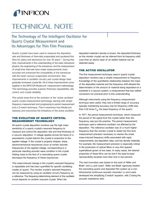
TECHNICAL NOTE<strong>The</strong> Technology of <strong>The</strong> <strong>Intelligent</strong> <strong>Oscillator</strong> <strong>for</strong><strong>Quartz</strong> <strong>Crystal</strong> <strong>Measurement</strong> andIts Advantages <strong>for</strong> Thin Film Processes<strong>Quartz</strong> crystals have been used to measure the depositionrate and thickness of thermally evaporated and sputtered thinfilms <strong>for</strong> optics and electronics <strong>for</strong> over 30 years 1,2 . During thattime, improvements in the understanding of the basic transducerphysics, the engineering of the transducer, and the measurementof small time intervals have made measurements moreaccurate and enhanced the compatibility of the transducerwith the harsh vacuum evaporation environment. Alsoimprovements in oscillator circuitry and crystal design havegradually increased crystal life. All of these improvements cometogether in the <strong>INFICON</strong> ModeLock 3 measurement methodology.This technology provides superior thickness repeatability, ratecontrol, and crystal reliability.This article looks first at the evolution of the “active oscillator”quartz crystal measurement technology, starting with simplefrequency measurement and progressing to period measurementand a Z-match technique. <strong>The</strong>n it examines how ModeLockreplaces and overcomes the limitations of the active oscillator.THE EVOLUTION OF QUARTZ CRYSTALMEASUREMENT TECHNOLOGYAll quartz crystal deposition monitors use the high masssensitivity of a quartz crystal’s resonant frequency tomeasure and control the deposition rate and final thickness ofa vacuum deposition. A voltage applied across the faces of apiezoelectric crystal distorts the crystal in proportion to theapplied voltage. If the crystal is properly shaped, sharpelectromechanical resonances occur at certain discretefrequencies of the applied voltage, corresponding to aparticular standing acoustic wave condition in the crystal.Adding mass to the face of a resonating quartz crystaldecreases the frequency of these resonances.This mass-induced change in the crystal’s resonant frequencyis repeatable and has been quantified <strong>for</strong> specific oscillatingmodes of quartz. <strong>The</strong> monitor crystal’s resonant frequencycan be measured by using an oscillator circuit’s frequency asa reference. <strong>The</strong> frequency-determining element of the oscillatorcircuit depends on another resonant crystal. When thedeposited material’s density is known, the deposited thicknesson the monitor crystal can be inferred from its frequency shift.Less than an atomic layer of an added material can bedetected easily.THE ACTIVE OSCILLATOR<strong>The</strong> first measurement technique used in quartz crystaldeposition monitors was a simple measurement of frequency.Knowledge of the quantitative relationship between the massof the deposited material and the frequency shift allowed thedetermination of the amount of material being deposited on asubstrate in a vacuum system, a measurement that was neitherconvenient nor practical prior to this understanding.Although instruments using the frequency measurementtechnique were useful, they had a limited range of accuracy,typically maintaining accuracy only <strong>for</strong> frequency shifts lessthan 0.02 times F q , the base frequency of the quartz.In 1971, the period measurement technique, which measuredthe period of the signal from the crystal rather than thefrequency, was put into practice. <strong>The</strong> period measurementtechnique used a reference oscillator not affected by thedeposition. <strong>The</strong> reference oscillator was of a much higherfrequency than the monitor crystal to obtain the fine timemeasurement precision necessary to resolve the small,mass-induced frequency shifts associated with rapidmeasurements, low deposition rates, and low density materials.For example, the measurement precision is especially criticalin the production of optical filters or very thin layeredsuperlattices grown at low rates. In many cases, the desiredproperties of these films can be lost if the layer-to-layerreproducibility exceeds more than one or two percent.<strong>The</strong> next innovation was based on the work of Miller andBolef 4 and Lu and Lewis 5 .Miller and Bolef rigorously treatedthe resonating quartz and deposited film system as a onedimensionalcontinuous acoustic resonator. Lu and Lewisdeveloped the simplifying Z-match 6 equation, with Z being theacoustic impedance ratio.
Technisches DatenblattFluidflon PTFE-SchlauchTypische physikalische Eigenschaften von Fluidflon PTFETypical physical properties of Fluidflon PTFETypische physikalische Eigenschaften/Typical Physical PropertiesASTM MethodWert / ValueHärte / Hardness Shore 15 A, 15 sec D2240-02 58Farbe / Colordurchsichtig/ translucentZugfestigkeit / Tensile Strength, psi (MPa) D412-98 2650 (18,3)Maximale Dehnung / Ultimate elongation (%) D412-98 250Dichte / Specific Gravity D792-00 2,18Wasserabsorption / Water Absorption D570-98 < 0,01Empfohlene maximale Betriebstemperatur/Maximum recommended operating temperature (° C)D746-98 268Sterilisationsverfahren / Sterilization MethodAutoklavierbar / Autoclavable 1 Gas 2 Bestrahlung / Radiation 3ja/yes ja/yes nein/no(1) 30 Minuten Dampf mit einen Druck von 1 Bar (141° C) /Stream 30 minutes at 1 bar (141° C)(2) Ethylenoxid / Ethylene oxide(3) Bestrahlung bis zu 2,5 Mrad / Radiationup to 2,5 MradFaust<strong>for</strong>mel Biegeradiusmin. Biegeradius = Außendurchmesser 2 / Wandstärkez.B.: PTFE-Schlauch mit Außendurchmesser 6,0mm und Wandstärke 2,0 mmmin. Biegeradius = 6,0 2 mm 2 /2,0mm = 18,0 mmEINE LISTE DER LIEFERBAREN ABMESSUNGEN, SOWIE WEITERE DATENBLÄTTER ZU UNSEREN SCHLÄUCHEN FINDEN SIE UNTERwww.liquid-scan.deDie aufgeführten Angaben sind nach eigenen Prüfungen, Empfehlungen unserer Grundstofflieferanten sowie Erfahrungsberichten unserer Kunden erarbeitet und zusammengetragen worden.Da individuelle Betriebsbedingungen die Einsetzbarkeit jedes Schlauches zusätzlich beeinflussen, können die Angaben nur Richtwerte darstellen. In Fällen, in denen noch keineEinsatzerfahrungen vorliegen, empfehlen wir, um Risiken zu vermeiden, einen Vorversuch beim Anwender. Dies empfiehlt sich besonders bei Stoffgemischen.SEITE 2 VON 4 zuletzt bearbeitet: 12.09.2012/ MPProLiquid GmbH – Fachbereich: LIQUID-scan - Heiligenbreite 19 - 88662 Überlingen - Tel: 07551/ 301770 - Fax: 07551/ 932959 - www.liquid-scan.de - info@liquid-scan.de
frequency to another. <strong>The</strong> monitor often continues to operateunder these conditions since there is no outward evidence ofmode hopping except <strong>for</strong> a discontinuity in the film thickness,as is shown in Figure 5. Although the apparent thicknesschanges dramatically, the mass sensitivity, and there<strong>for</strong>e thetrue rate, changes only by about five percent.THE CRYSTAL’S SERIES RESISTANCE OR“ACTIVITY”<strong>The</strong> greater the crystal’s response to the applied voltage, themore likely it is that the crystal will continue to oscillate asmaterial is added. This quality is sometimes called activity orcomplex impedance, but the effect is more properly related tothe series resistance. Higher series resistance means that lesscurrent is accepted and returned from the crystal. Since thephysical motion of the crystal is current-driven, low currentlevels produce little piezoelectric motion. A new 6 MHz monitorcrystal will typically have less than 10 or 20 ohms of seriesresistance at the fundamental mode. A conventional oscillatorcircuit will continue to operate well until the series resistanceof the crystal exceeds approximately 200 ohms. Forwell-behaved materials, such as copper, this resistance is notnormally exceeded, even <strong>for</strong> a frequency shift in excess of 1MHz. Although these oscillators will continue to resonate witha crystal that has a high resistance, they are often unable toinitiate the oscillation of a high-resistance crystal after adisconnection or power failure.In practice, the series resistance is not a strict predictor ofcontinued operation. Because of low mobility, some materialsdo not deposit as continuous films on the crystal surface buttake on an amorphous, granular texture, through which theacoustic wave is unable to propagate continuously. In thesecases, the crystal can be used <strong>for</strong> only very thin layers. <strong>The</strong>series resistance is not initially affected, but, when it doesincrease, it does so unexpectedly and precipitously.Film stress can also affect crystal life. Stress can bend thecrystal and induce a frequency change not related to mass, orit can cause the electrode to tear from the quartz. Stress cancause a quick and unpredictable failure during deposition oreven destroy a crystal during system venting. If the electrodeis strongly adhered to the quartz, the combination of rapidtemperature change and moisture adsorption increases stressuntil the quartz itself fractures.MODELOCK: A FREQUENCY-SYNTHESIZED,PHASE-SENSITIVE, INTELLIGENTOSCILLATORIn 1990, <strong>INFICON</strong> introduced a new technology that replacesthe active oscillator and overcomes the active oscillator’slimitations. This measurement system, ModeLock, constantlytests the crystal’s response to an applied frequency. It not onlydetermines the resonant frequency but also verifies that thecrystal is oscillating in the desired mode. ModeLock isessentially immune to mode hopping and thus is not subject tothe thickness and rate inaccuracies of active oscillators. It isfast and accurate, determining the crystal’s frequency withprecision better than 0.0055 Hz at a rate of 10 times per second.This new intelligent measurement system uses the phase/frequency properties of the quartz crystal to determine theresonant frequency. As shown in Figure 6, it applies asynthesized sine wave of a specific frequency to the crystaland measures the phase difference between the applied signalvoltage and the current passing through the crystal. When acrystal operates at series resonance, this phase difference isexactly zero degrees; the crystal behaves as if it were pureresistance. <strong>The</strong> reactances of the inductive and capacitivebranches cancel each other.Figure 6UP TOTWO METERSXTALDUPLEXERCIRCUITSIGNALAMPLIFIER& LIMITERSIGNALLEVELDETECTORCABLECOMPREFERENCEAMPLIFIER& LIMITERPHASEDETECTOROUTPUTDRIVEROUTPUTDRIVERDIRECTSIGNALSYNTHESIZERANALOGTODIGITALCONVERTERMICRO-CONTROLLERDIGITALTOANALOGCONVERTERDIGITALLINKBy separating the applied voltage and the current returned fromthe crystal and by monitoring the output of a phase comparator,ModeLock determines whether the applied frequency is higheror lower than the crystal’s resonant frequency. At frequencieswell below any resonance, the crystal’s impedance is capacitive.In terms of phase angle, the current leads the voltage. Atfrequencies slightly higher than resonance, a crystal’s impedanceis inductive in nature. This is valuable in<strong>for</strong>mation if theresonance frequencies can be applied to the crystal, with achange in sign of the phase comparator marking the resonanceevents. For AT-cut crystals, the type used in ModeLock
instruments, the lowest frequency event encountered is thefundamental. <strong>The</strong> events slightly higher in frequency areanharmonics.This in<strong>for</strong>mation is beneficial not only <strong>for</strong> initialization, but also<strong>for</strong> the rare instances when the instrument loses track of thefundamental.Once the resonance spectrum of the crystal is determined, theinstrument tracks the changing frequencies and periodicallyprovides frequency measurements <strong>for</strong> subsequent conversionto thickness. Rather than sweep the applied frequency overthe entire range of possible frequencies <strong>for</strong> each measurement,a more efficient strategy based on a phase-change algorithmprecisely determines the resonant frequency. <strong>The</strong> algorithmadjusts the applied frequency according to phase changein<strong>for</strong>mation and allows a “lock” on the resonant frequency. Adirect digital synthesizer, or DDS, closely coupled to a dedicatedmicroprocessor and related circuitry, makes this processpossible at unprecedented speed and frequency accuracy—and at a practical cost. All the necessary actions—comparingthe phase, digitizing the phase difference, comparing thatvalue to the desired value, deciding to increase or decreasethe applied frequency, then generating the new frequency—can take place 150,000 times per second.<strong>The</strong> result is that ModeLock offers significant advantages overactive oscillators: immunity from mode hopping, increasedspeed of measurement, improved precision of measurement,and extended crystal life in many applications. <strong>The</strong> techniquealso allows <strong>for</strong> the automatic determination of the acousticimpedance parameter, the Z-ratio, a feature that is impossiblewith the active-oscillator approach. <strong>The</strong> patented* Auto-Ztechnique is discussed in detail in the literature 8 .1G.Z. Sauerbrey, Z. Phys., 155 206 (1959).2K.H. Behrndt and R.W. Love, Vacuum 12, 1-9 (1962)3U.S. patent #5,117,192. International patents pending.4J.G. Miller and D.I. Bolef, J. Appl. Phys. 39, 5815 (1968).5C. Lu and O. Lewis, J. Appl. Phys. 43, 4385 (1972).6Z-match is a registered trademark of <strong>INFICON</strong>.7C. Lu, J. Vac. Sci. Technol. 12(1), 581 (1975).8A. Wajid, Rev. Sci. Instrum. 62(8), 2026 (1991).*U.S. Patent #5,112,642.GLOBAL HEADQUARTERS:Two Technology Place, East Syracuse, NY 13057 USATel: +1.315.434.1100 Fax: +1.315.437.3803 E-mail: reachus@inficon.comUNITED STATES FRANCE GERMANY LIECHTENSTEIN SWITZERLAND UNITED KINGDOM CHINA JAPAN KOREA SINGAPORE TAIWANVisit our website <strong>for</strong> contact in<strong>for</strong>mation and other sales offices worldwide. www.inficon.comZ-Match is a registered trademark of <strong>INFICON</strong>.cicb91a1 ©2002 <strong>INFICON</strong>