R&S®RT-ZF2 Manual - Rohde & Schwarz
R&S®RT-ZF2 Manual - Rohde & Schwarz
R&S®RT-ZF2 Manual - Rohde & Schwarz

You also want an ePaper? Increase the reach of your titles
YUMPU automatically turns print PDFs into web optimized ePapers that Google loves.
R&S ® RT-<strong>ZF2</strong>Ethernet ComplianceTest Fixture Set<strong>Manual</strong>(=AÅÁ2)1317.5551.02 ─ 02Test & Measurement<strong>Manual</strong>
This manual describes the R&S RT-<strong>ZF2</strong> Ethernet Compliance Test Fixture Set(1317.5522.02).© 2013 <strong>Rohde</strong> & <strong>Schwarz</strong> GmbH & Co. KGMühldorfstr. 15, 81671 München, GermanyPhone: +49 89 41 29 - 0Fax: +49 89 41 29 12 164E-mail: info@rohde-schwarz.comInternet: www.rohde-schwarz.comSubject to change – Data without tolerance limits is not binding.R&S ® is a registered trademark of <strong>Rohde</strong> & <strong>Schwarz</strong> GmbH & Co. KG.Trade names are trademarks of the owners.The following abbreviations are used throughout this manual: R&S ® RTO is abbreviated as R&S RTO, andR&S ® ScopeSuite is abbreviated as R&S ScopeSuite.
Basic Safety InstructionsSignal words and their meaningThe following signal words are used in the product documentation in order towarn the reader about risks and dangers.Indicates a hazardous situation which, if not avoided, willresult in death or serious injury.Indicates a hazardous situation which, if not avoided, couldresult in death or serious injury.Indicates a hazardous situation which, if not avoided, couldresult in minor or moderate injury.Indicates information considered important, but not hazardrelated,e.g. messages relating to property damage.In the product documentation, the word ATTENTION isused synonymously.These signal words are in accordance with the standard definition for civilapplications in the European Economic Area. Definitions that deviate from thestandard definition may also exist in other economic areas or military applications.It is therefore essential to make sure that the signal words described here arealways used only in connection with the related product documentation and therelated product. The use of signal words in connection with unrelated products ordocumentation can result in misinterpretation and in personal injury or materialdamage.Operating states and operating positionsThe product may be operated only under the operating conditions and in thepositions specified by the manufacturer, without the product's ventilation beingobstructed. If the manufacturer's specifications are not observed, this can result inelectric shock, fire and/or serious personal injury or death. Applicable local ornational safety regulations and rules for the prevention of accidents must beobserved in all work performed.1. Unless otherwise specified, the following requirements apply to <strong>Rohde</strong> &<strong>Schwarz</strong> products:predefined operating position is always with the housing floor facing down, IPprotection 2X, use only indoors, max. operating altitude 2000 m above sealevel, max. transport altitude 4500 m above sea level. A tolerance of ±10 %shall apply to the nominal voltage and ±5 % to the nominal frequency,overvoltage category 2, pollution severity 2.1171.0000.52 - 07 Page 3
Basic Safety Instructions5. Never use the product if the power cable is damaged. Check the power cableson a regular basis to ensure that they are in proper operating condition. Bytaking appropriate safety measures and carefully laying the power cable,ensure that the cable cannot be damaged and that no one can be hurt by, forexample, tripping over the cable or suffering an electric shock.6. The product may be operated only from TN/TT supply networks fuse-protectedwith max. 16 A (higher fuse only after consulting with the <strong>Rohde</strong> & <strong>Schwarz</strong>group of companies).7. Do not insert the plug into sockets that are dusty or dirty. Insert the plug firmlyand all the way into the socket provided for this purpose. Otherwise, sparksthat result in fire and/or injuries may occur.8. Do not overload any sockets, extension cords or connector strips; doing socan cause fire or electric shocks.9. For measurements in circuits with voltages V rms > 30 V, suitable measures(e.g. appropriate measuring equipment, fuse protection, current limiting,electrical separation, insulation) should be taken to avoid any hazards.10. Ensure that the connections with information technology equipment, e.g. PCsor other industrial computers, comply with the IEC60950-1/EN60950-1 orIEC61010-1/EN 61010-1 standards that apply in each case.11. Unless expressly permitted, never remove the cover or any part of the housingwhile the product is in operation. Doing so will expose circuits andcomponents and can lead to injuries, fire or damage to the product.12. If a product is to be permanently installed, the connection between theprotective conductor terminal on site and the product's protective conductormust be made first before any other connection is made. The product may beinstalled and connected only by a licensed electrician.13. For permanently installed equipment without built-in fuses, circuit breakers orsimilar protective devices, the supply circuit must be fuse-protected in such away that anyone who has access to the product, as well as the product itself,is adequately protected from injury or damage.14. Use suitable overvoltage protection to ensure that no overvoltage (such asthat caused by a bolt of lightning) can reach the product. Otherwise, theperson operating the product will be exposed to the danger of an electricshock.15. Any object that is not designed to be placed in the openings of the housingmust not be used for this purpose. Doing so can cause short circuits inside theproduct and/or electric shocks, fire or injuries.1171.0000.52 - 07 Page 5
Basic Safety Instructions16. Unless specified otherwise, products are not liquid-proof (see also section"Operating states and operating positions", item 1). Therefore, the equipmentmust be protected against penetration by liquids. If the necessary precautionsare not taken, the user may suffer electric shock or the product itself may bedamaged, which can also lead to personal injury.17. Never use the product under conditions in which condensation has formed orcan form in or on the product, e.g. if the product has been moved from a coldto a warm environment. Penetration by water increases the risk of electricshock.18. Prior to cleaning the product, disconnect it completely from the power supply(e.g. AC supply network or battery). Use a soft, non-linting cloth to clean theproduct. Never use chemical cleaning agents such as alcohol, acetone ordiluents for cellulose lacquers.Operation1. Operating the products requires special training and intense concentration.Make sure that persons who use the products are physically, mentally andemotionally fit enough to do so; otherwise, injuries or material damage mayoccur. It is the responsibility of the employer/operator to select suitablepersonnel for operating the products.2. Before you move or transport the product, read and observe the section titled"Transport".3. As with all industrially manufactured goods, the use of substances that inducean allergic reaction (allergens) such as nickel cannot be generally excluded. Ifyou develop an allergic reaction (such as a skin rash, frequent sneezing, redeyes or respiratory difficulties) when using a <strong>Rohde</strong> & <strong>Schwarz</strong> product,consult a physician immediately to determine the cause and to prevent healthproblems or stress.4. Before you start processing the product mechanically and/or thermally, orbefore you take it apart, be sure to read and pay special attention to thesection titled "Waste disposal/Environmental protection", item 1.5. Depending on the function, certain products such as RF radio equipment canproduce an elevated level of electromagnetic radiation. Considering thatunborn babies require increased protection, pregnant women must beprotected by appropriate measures. Persons with pacemakers may also beexposed to risks from electromagnetic radiation. The employer/operator mustevaluate workplaces where there is a special risk of exposure to radiation and,if necessary, take measures to avert the potential danger.1171.0000.52 - 07 Page 6
Basic Safety Instructions6. Should a fire occur, the product may release hazardous substances (gases,fluids, etc.) that can cause health problems. Therefore, suitable measuresmust be taken, e.g. protective masks and protective clothing must be worn.7. Laser products are given warning labels that are standardized according totheir laser class. Lasers can cause biological harm due to the properties oftheir radiation and due to their extremely concentrated electromagnetic power.If a laser product (e.g. a CD/DVD drive) is integrated into a <strong>Rohde</strong> & <strong>Schwarz</strong>product, absolutely no other settings or functions may be used as described inthe product documentation. The objective is to prevent personal injury (e.g.due to laser beams).8. EMC classes (in line with EN 55011/CISPR 11, and analogously with EN55022/CISPR 22, EN 55032/CISPR 32)− Class A equipment:Equipment suitable for use in all environments except residentialenvironments and environments that are directly connected to a lowvoltagesupply network that supplies residential buildingsNote: Class A equipment is intended for use in an industrial environment.This equipment may cause radio disturbances in residential environments,due to possible conducted as well as radiated disturbances. In this case,the operator may be required to take appropriate measures to eliminatethese disturbances.− Class B equipment:Equipment suitable for use in residential environments and environmentsthat are directly connected to a low-voltage supply network that suppliesresidential buildingsRepair and service1. The product may be opened only by authorized, specially trained personnel.Before any work is performed on the product or before the product is opened,it must be disconnected from the AC supply network. Otherwise, personnel willbe exposed to the risk of an electric shock.2. Adjustments, replacement of parts, maintenance and repair may be performedonly by electrical experts authorized by <strong>Rohde</strong> & <strong>Schwarz</strong>. Only original partsmay be used for replacing parts relevant to safety (e.g. power switches, powertransformers, fuses). A safety test must always be performed after partsrelevant to safety have been replaced (visual inspection, protective conductortest, insulation resistance measurement, leakage current measurement,functional test). This helps ensure the continued safety of the product.1171.0000.52 - 07 Page 7
Basic Safety InstructionsBatteries and rechargeable batteries/cellsIf the information regarding batteries and rechargeable batteries/cells is notobserved either at all or to the extent necessary, product users may be exposedto the risk of explosions, fire and/or serious personal injury, and, in some cases,death. Batteries and rechargeable batteries with alkaline electrolytes (e.g. lithiumcells) must be handled in accordance with the EN 62133 standard.1. Cells must not be taken apart or crushed.2. Cells or batteries must not be exposed to heat or fire. Storage in direct sunlightmust be avoided. Keep cells and batteries clean and dry. Clean soiledconnectors using a dry, clean cloth.3. Cells or batteries must not be short-circuited. Cells or batteries must not bestored in a box or in a drawer where they can short-circuit each other, orwhere they can be short-circuited by other conductive materials. Cells andbatteries must not be removed from their original packaging until they areready to be used.4. Cells and batteries must not be exposed to any mechanical shocks that arestronger than permitted.5. If a cell develops a leak, the fluid must not be allowed to come into contactwith the skin or eyes. If contact occurs, wash the affected area with plenty ofwater and seek medical aid.6. Improperly replacing or charging cells or batteries that contain alkalineelectrolytes (e.g. lithium cells) can cause explosions. Replace cells or batteriesonly with the matching <strong>Rohde</strong> & <strong>Schwarz</strong> type (see parts list) in order toensure the safety of the product.7. Cells and batteries must be recycled and kept separate from residual waste.Rechargeable batteries and normal batteries that contain lead, mercury orcadmium are hazardous waste. Observe the national regulations regardingwaste disposal and recycling.Transport1. The product may be very heavy. Therefore, the product must be handled withcare. In some cases, the user may require a suitable means of lifting ormoving the product (e.g. with a lift-truck) to avoid back or other physicalinjuries.2. Handles on the products are designed exclusively to enable personnel totransport the product. It is therefore not permissible to use handles to fastenthe product to or on transport equipment such as cranes, fork lifts, wagons,1171.0000.52 - 07 Page 8
Basic Safety Instructionsetc. The user is responsible for securely fastening the products to or on themeans of transport or lifting. Observe the safety regulations of themanufacturer of the means of transport or lifting. Noncompliance can result inpersonal injury or material damage.3. If you use the product in a vehicle, it is the sole responsibility of the driver todrive the vehicle safely and properly. The manufacturer assumes noresponsibility for accidents or collisions. Never use the product in a movingvehicle if doing so could distract the driver of the vehicle. Adequately securethe product in the vehicle to prevent injuries or other damage in the event ofan accident.Waste disposal/Environmental protection1. Specially marked equipment has a battery or accumulator that must not bedisposed of with unsorted municipal waste, but must be collected separately. Itmay only be disposed of at a suitable collection point or via a<strong>Rohde</strong> & <strong>Schwarz</strong> customer service center.2. Waste electrical and electronic equipment must not be disposed of withunsorted municipal waste, but must be collected separately.<strong>Rohde</strong> & <strong>Schwarz</strong> GmbH & Co. KG has developed a disposal concept andtakes full responsibility for take-back obligations and disposal obligations formanufacturers within the EU. Contact your <strong>Rohde</strong> & <strong>Schwarz</strong> customerservice center for environmentally responsible disposal of the product.3. If products or their components are mechanically and/or thermally processedin a manner that goes beyond their intended use, hazardous substances(heavy-metal dust such as lead, beryllium, nickel) may be released. For thisreason, the product may only be disassembled by specially trained personnel.Improper disassembly may be hazardous to your health. National wastedisposal regulations must be observed.4. If handling the product releases hazardous substances or fuels that must bedisposed of in a special way, e.g. coolants or engine oils that must bereplenished regularly, the safety instructions of the manufacturer of thehazardous substances or fuels and the applicable regional waste disposalregulations must be observed. Also observe the relevant safety instructions inthe product documentation. The improper disposal of hazardous substancesor fuels can cause health problems and lead to environmental damage.For additional information about environmental protection, visit the<strong>Rohde</strong> & <strong>Schwarz</strong> website.1171.0000.52 - 07 Page 9
R&S ® RT-<strong>ZF2</strong>ContentsContents1 Product Description.............................................................. 51.1 Usage Information................................................................................ 51.2 Deliveries............................................................................................... 51.3 Test Equipment..................................................................................... 61.4 Specifications........................................................................................72 Ethernet Test Fixture Boards............................................... 82.1 Ethernet Test Board..............................................................................82.2 Calibration Board................................................................................113 Preparing the Measurements............................................. 123.1 Installing Software and License........................................................ 123.2 Setting Up the Network...................................................................... 133.3 Connecting the R&S RTO...................................................................143.4 Connecting the Arbitrary Waveform Generator............................... 163.5 Connecting the Vector Network Analyzer........................................ 183.6 Configuring the Test...........................................................................193.7 Initiating the Test................................................................................ 22<strong>Manual</strong> 1317.5551.02 ─ 023
R&S ® RT-<strong>ZF2</strong>Contents<strong>Manual</strong> 1317.5551.02 ─ 024
R&S ® RT-<strong>ZF2</strong>1 Product DescriptionProduct DescriptionUsage InformationThe R&S RT‐<strong>ZF2</strong> Ethernet compliance test fixture set is a product for testing ofEthernet standards 10BASE-T, 100BASE-TX, 1000BASE-T, 10GBASE-T. It isused in combination with the R&S RTO oscilloscopes, with the R&S RTO-K22Ethernet compliance test option (1317.4678.02) and the R&S ScopeSuite software.1.1 Usage InformationThe equipment under test (EUT) is an ethernet signal quality test and developmentboard, indented to be used at laboratory or test and measurement areas.These areas are specifically used for analysis, testing and servicing and whereequipment is operated by trained personnel.The Ethernet test fixture boards are designed for testing Ethernet devices usingRJ-45 connectors.Risk of injury and instrument damageMake sure to connect only Ethernet devices with RJ-45 interface that aredesigned according to IEEE802.3 10BASE-T, 100BASE-T/TX, 1000BASE-T or 10GBASE-T.Use the boards in an appropriate manner to prevent electric shock, personalinjury, or damage. Read and observe the "Basic Safety Instructions"at the beginning of this manual.1.2 DeliveriesThe R&S RT‐<strong>ZF2</strong> comprises two test boards and accessories.<strong>Manual</strong> 1317.5551.02 ─ 025
R&S ® RT-<strong>ZF2</strong>Product DescriptionTest Equipment1.2.1 BoardsThe main components of Ethernet compliance test fixture set are two test boards:● Ethernet test fixture (1317.5539.02)● Calibration board (1317.5539.02)See also: chapter 2, "Ethernet Test Fixture Boards", on page 8.1.2.2 AccessoriesThe following accessories are supplied with the Ethernet test fixture boards:Item Quantity Order numberEthernet cable CAT6 1 3033.9264.00SMA terminations 3 0249.7823.00Carrying case 1<strong>Manual</strong> 1The following optional accessories are available:Item Type Order numberGigabit Ethernet Jitter Cable for 1000BASE-T jitterslave mode test103 m cable with specific sections of differentimpedance that cause signal distortionsR&S RT‐<strong>ZF2</strong>C 1317.5639.021.3 Test EquipmentFor Ethernet compliance tests using the test fixture set, the following test equipmentis recommended:●●●R&S RTO oscilloscope with at least 600 MHz bandwidth: R&S RTO1002, orR&S RTO1004 or higher.Differential probe with at least 1 GHz bandwidth: R&S RT‐ZD10 or higherR&S RTO-K22 Ethernet compliance test option (required option, installed onthe R&S RTO)<strong>Manual</strong> 1317.5551.02 ─ 026
●●●R&S ® RT-<strong>ZF2</strong>Product DescriptionSpecificationsR&S ScopeSuite software, which contains the Ethernet compliance test,requires Windows 7 operating systemTabor WX2182B or HAMEG HMF2550 arbitrary waveform generator for disturbertestsR&S ZVL or R&S ZNB vector network analyzer for return loss measurements1.4 SpecificationsThis section contains the specifications of the R&S Ethernet compliance test fixture.Specifications with limits represent warranted product performance by means of arange of values for the specified parameter.Temperature loading operating temperature range 0 °C to +45 °Cstorage temperature range -40 °C to +70 °C<strong>Manual</strong> 1317.5551.02 ─ 027
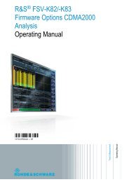
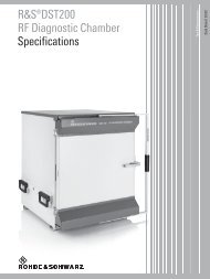
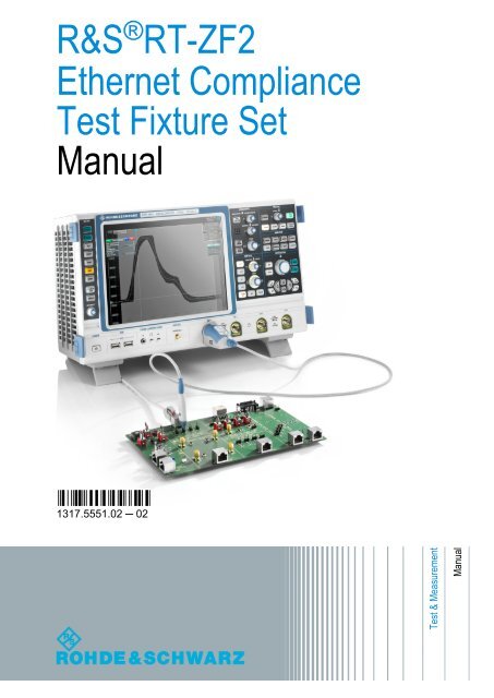
R&S ® RT-<strong>ZF2</strong>2 Ethernet Test Fixture BoardsEthernet Test Fixture BoardsEthernet Test BoardThe Ethernet test fixture R&S ScopeSuite consists of two boards: the Ethernettest board and the calibration board.2.1 Ethernet Test BoardThe ethernet test board has several labeled sections designed for specific testcases. The board is shown in figure 2-1. The assignment of the test cases to theboard sections is shown in table 2-1.You can cut the board at the section limits and use each section as a separateboard.<strong>Manual</strong> 1317.5551.02 ─ 028
R&S ® RT-<strong>ZF2</strong>Ethernet Test Fixture BoardsEthernet Test BoardX203LinkPartnerX206X200S200X201w/oTPM TPM1S201 S204Loads 100RX202w/oTPM TPMLoad2S202 Load1Twisted Pair ModelX300X307X303Ch.DCh.B2Ch.CCh.AResistive LoadREthernet Test FixtureSRT-<strong>ZF2</strong>Return LossX305X301X110X108X109X111B A C D3X107X4024 5D C A BX403 X404 X406 X405Common Mode OutputVoltageResistive Load withDistorsion SourceX506X501S501 S500 S502 S503X503 X502 X504 X505B A C DX500X700X600A Jitter Slave Test 1000BaseTX705 BX704 C6X702 DX703X602DJitter Slave Test 10GBaseT7X603X701MasterX601MasterFig. 2-1: Ethernet test board<strong>Manual</strong> 1317.5551.02 ─ 029
R&S ® RT-<strong>ZF2</strong>Ethernet Test Fixture BoardsEthernet Test Board1 = Twisted Pair Model2 = Return Loss3 = Resistive Load4 = Common Mode Output Voltage5 = Resistive Load with Distorsion Source6 = Jitter Slave Test 1000BASET7 = Jitter Slave Test 10GBASETTable 2-1: Test cases supported by the Ethernet test fixture boardTest caseDisturberSection1 2 3 4 5 6 7ARB1000BASE-T test casesPeak differential output voltage and levelaccuracyMaximum output droopDifferential output templatesTransmitter distortionPeak differential output voltage and levelaccuracyMaximum output droopDifferential output templatesTransmitter distortionNo xYes x xCommon-mode output voltage xTransmitter timing jitter (master mode) x xTransmitter timing jitter (slave mode) xMDI return loss x100BASE-TX test casesAmplitude domain tests xTime domain test xTotal transmit jitter xDuty cycle distorsion xAOI template test xReturn loss x<strong>Manual</strong> 1317.5551.02 ─ 0210
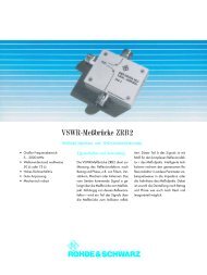
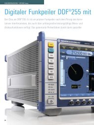
R&S ® RT-<strong>ZF2</strong>Ethernet Test Fixture BoardsCalibration BoardSectionTest caseDisturber1 2 3 4 5 6 710BASE-T test casesHarmonic content xARBOutput timing jitter xMAU template xTP_IDL xLink test pulse xCommon-mode output voltage xReturn loss xX206 jumperThe X206 jumper switches the link partner on or off. It is used in 10BASE-T testcases.X200X206X203LinkPartner●●Left position: Link partner is connected.Right position: Link partner is disconnected.2.2 Calibration BoardThe calibration board is required in return loss measurements. It is used to calibratethe vector network analyzer for the measurement.Calibration Board for RT-<strong>ZF2</strong>Open Short MatchX100 X101 X102Fig. 2-2: Ethernet calibration board<strong>Manual</strong> 1317.5551.02 ─ 0211
R&S ® RT-<strong>ZF2</strong>Preparing the MeasurementsInstalling Software and License3 Preparing the Measurements3.1 Installing Software and LicenseThe preparation steps have to be performed only once for each computer andinstrument that are used for testing.Uninstall older versions of the R&S ScopeSuiteIf an older version of the R&S ScopeSuite is installed on the test computer,make sure to uninstall the old version before you install the new one. Youcan find the version number of the current installation in "Help" menu >"About". To unistall the R&S ScopeSuite, use the Windows Control Panel >"Programs".To install the R&S ScopeSuite on the test computer1. Download the R&S ScopeSuite software from the "Downloads > Software"section on the <strong>Rohde</strong> & <strong>Schwarz</strong> "Scope of the Art" web page: www.scope-ofthe-art.com/product/rto.html.2. Install the R&S ScopeSuite software on the computer that is used for testing.To install the license key on the R&S RTO► When you got the license key of the R&S RTO‐K22 option, enable it usingSETUP > "SW Options".For a detailed description, refer to the R&S RTO User <strong>Manual</strong>, chapter "InstallingOptions", or to the online help on the instrument.To install the MATLAB Compiler Runtime on the test computerFor some of the 1000BASE-T test cases you have to install the MATLAB CompilerRuntime (MCR) on the computer that is running the R&S ScopeSuite. TheR2012b Windows 32-bit version is required.1. Download the "R2012b Windows 32-bit" MCR installation file from www.mathworks.com/products/compiler/mcr/and save it to the test computer.<strong>Manual</strong> 1317.5551.02 ─ 0212
R&S ® RT-<strong>ZF2</strong>Preparing the MeasurementsSetting Up the Network2. Double-click the installation file and follow the instruction in the installationwizard.3.2 Setting Up the NetworkThe computer running the R&S ScopeSuite software and the testing R&S RTOrequire a LAN connection.There are two ways of connection:●●LAN (local area network): It is recommended that you connect to a LAN withDHCP server. This server uses the Dynamic Host Configuration Protocol(DHCP) to assign all address information automatically.Direct connection of the instruments and the computer or connection to aswitch using LAN cables: Assign fixed IP addresses to the computer and theinstruments and reboot all devices.<strong>Manual</strong> 1317.5551.02 ─ 0213
R&S ® RT-<strong>ZF2</strong>Preparing the MeasurementsFor some test cases, you need an arbitrary waveform generator (ARB). The ARBcan be used in automatic or manual mode. Automated tests require a LAN connectionand a VISA installation on the test computer (NI-VISA, Agilent-VISA, orTektronic-VISA 4.0 and above). In manual mode, VISA is not required. TheR&S ScopeSuite uses VISA if it is installed, otherwise it uses the VXI-11 protocol.Fixed IP addresses are required if the Tabor WX2182B is used for automatic testing.To set up and test the LAN connection1. Connect the computer and the instruments to the same LAN.2. Start all devices.3. If no DHCP server is available, assign fixed IP addresses to all devices.4. Ping the instruments to make sure that the connection has been established.5. If VISA is installed, check if VISA can access the instruments:a) Start VISA on the test computer.b) Validate the VISA address string of each device.Connecting the R&S RTO6. If the connection to the Tabor arbitrary waveform generator failed, check onthe instrument if the IP address is assigned correctly.3.3 Connecting the R&S RTOThe computer running the R&S ScopeSuite software and the testing R&S RTOrequire a LAN connection.1. Connect the computer and the R&S RTO and set up the LAN connection, seechapter 3.2, "Setting Up the Network", on page 13.2. Start the R&S RTO.3. Start the R&S ScopeSuite software on the computer.4. Click "Instrument Settings".<strong>Manual</strong> 1317.5551.02 ─ 0214
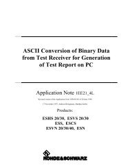
R&S ® RT-<strong>ZF2</strong>Preparing the MeasurementsConnecting the R&S RTO5. Click the "Oscilloscope" tab.6. Enter the IP address of the R&S RTO.To obtain the IP address, press the SETUP key on the instrument and tap the"System" tab.7. Click "Get Instrument Information".The computer connects with the instrument and gets the instrument data.<strong>Manual</strong> 1317.5551.02 ─ 0215
R&S ® RT-<strong>ZF2</strong>Preparing the MeasurementsConnecting the Arbitrary Waveform GeneratorIf the connection fails, an error message is shown.8. Click "Save".3.4 Connecting the Arbitrary Waveform GeneratorFor Ethernet tests using a disturber, an arbitrary waveform generator (ARB) isrequired. The tests can be performed manually or automatically, depending onthe the available ARB.Fast automatic test execution is possible with Tabor WX2182B or HAMEGHMF2550. In automatic mode, the R&S ScopeSuite configures the instrumentand ensures that the ARB sends the required waveforms. Automatic moderequires a LAN connection and the installation of a VISA implementation (NI-VISA, Agilent-VISA, Tektronic-VISA 4.0 and above) on the computer that is runningthe R&S ScopeSuite.For manual test execution it is recommended to use one of the listed ARBs.Moreover, any ARB can be used that has a sampling rate above 1.44 GSa/sec. Inmanual mode, you connect the ARB to the test board and configure the instrumentmanually.<strong>Manual</strong> 1317.5551.02 ─ 0216
R&S ® RT-<strong>ZF2</strong>Preparing the MeasurementsTo configure the arbitrary waveform generator for automatic testing1. Connect the computer and the ARB and set up the LAN connection, seechapter 3.2, "Setting Up the Network", on page 13.2. In the R&S ScopeSuite, click "Instrument Settings".3. Click the "Arbitrary Waveform Generator" tab.4. Select the "Test Setup": "USB" or "Ethernet".5. Select the "Automatic" operating mode.Connecting the Arbitrary Waveform Generator6. Select the "Arbitrary Waveform Generator" and enter its IP address.7. Click "Get Instrument Information".The computer connects with the instrument and retrieves the instrument data.8. Click "Save".To configure the ARB for manual testing► In the "Arbitrary Waveform Generator" tab, enable the "<strong>Manual</strong>" operatingmode.<strong>Manual</strong> 1317.5551.02 ─ 0217
R&S ® RT-<strong>ZF2</strong>Preparing the Measurements3.5 Connecting the Vector Network AnalyzerTo perform Ethernet return loss measurements, you need a vector network analyzer(VNA). Similar to the ARB, the VNA can be used in automatic or manualmode. Automatic mode is supported with R&S ZVL and R&S ZNB and requires aLAN connection and a VISA installation on the computer that is running theR&S ScopeSuite.In manual mode, you connect the vector network analyzer to the test board andconfigure the instrument manually.To connect the vector network analyzer for automatic testing1. Connect the computer and the VNA and set up the LAN connection, seechapter 3.2, "Setting Up the Network", on page 13.2. In the R&S ScopeSuite, click "Instrument Settings".3. Click the "Vector Network analyzer" tab.4. Select the "Automatic" operating mode.Connecting the Vector Network Analyzer5. Select the "Vector Network Analyzer" and enter its IP address.<strong>Manual</strong> 1317.5551.02 ─ 0218
R&S ® RT-<strong>ZF2</strong>Preparing the MeasurementsConfiguring the Test6. Click "Get Instrument Information".The computer connects with the instrument and retrieves the instrument data.7. Click "Save".3.6 Configuring the Test1. In the R&S ScopeSuite window, click "Ethernet Compliance Test".2. Click "Configuration".3. On the "User Input" tab, enter common information on the test.<strong>Manual</strong> 1317.5551.02 ─ 0219
R&S ® RT-<strong>ZF2</strong>Preparing the MeasurementsConfiguring the Test4. Click the "Test Configuration" tab.5. Check and adjust the configuration settings:●●●For 10BASE-T test cases, select the MAU Type, the type of the mediumattachment unit. Usually the MAU is integrated, and the type is internal.For 1000BASE-T test cases, select which cable pairs are uesd. You canomit this setting here and enter it when starting the test.Check and adjust the number of acquisitions to be used to calculate theaverage, to build the eye diagram and to measure the timing jitter.<strong>Manual</strong> 1317.5551.02 ─ 0220
R&S ® RT-<strong>ZF2</strong>Preparing the MeasurementsConfiguring the Test6. On the "Report Configuration" tab, select the format of the report and thedetails to be included in the report.<strong>Manual</strong> 1317.5551.02 ─ 0221
R&S ® RT-<strong>ZF2</strong>7. Click "OK".8. Click "Limit Editor".Preparing the MeasurementsInitiating the Test9. Select the "Test Type" in the lower left corner of the dialog box and check themeasurement limits.Each limit comprises the comparison criterion, the unit, the limit value A, and asecond limit value B if the criterion requires two limits.You can change the values in the table, export the table in xml format, orimport xml files with limit settings.3.7 Initiating the TestTo perform compliance tests, the device under test is connected to the test boardin a test-specific way. Using a probe, the test board is connected with theR&S RTO. The probe connections are test-specific. The R&S ScopeSuite guidesyou step-by-step through the connection setup and the test sequence.1. Set the test fixture on a nonconductive, static-approved work surface.2. In the R&S ScopeSuite window, click "Ethernet Compliance Test".<strong>Manual</strong> 1317.5551.02 ─ 0222
R&S ® RT-<strong>ZF2</strong>Preparing the MeasurementsInitiating the Test3. Click "Start Test".4. Select the test type and enter a name for the test session.5. Click "Next".The R&S ScopeSuite test wizard explains the following individual setup steps.A test description can be found in the "R&S Test Procedures" manual for theselected compliance test.<strong>Manual</strong> 1317.5551.02 ─ 0223