4320 - Jozwiak, L. M., J. W. Head III, M. T. Zuber, D. E. Smith, and ...
4320 - Jozwiak, L. M., J. W. Head III, M. T. Zuber, D. E. Smith, and ...
4320 - Jozwiak, L. M., J. W. Head III, M. T. Zuber, D. E. Smith, and ...

Create successful ePaper yourself
Turn your PDF publications into a flip-book with our unique Google optimized e-Paper software.
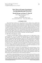
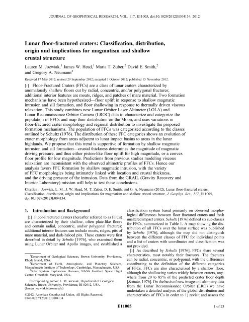
JOURNAL OF GEOPHYSICAL RESEARCH, VOL. 117, E11005, doi:10.1029/2012JE004134, 2012Lunar floor-fractured craters: Classification, distribution,origin <strong>and</strong> implications for magmatism <strong>and</strong> shallowcrustal structureLauren M. <strong>Jozwiak</strong>, 1 James W. <strong>Head</strong>, 1 Maria T. <strong>Zuber</strong>, 2 David E. <strong>Smith</strong>, 2<strong>and</strong> Gregory A. Neumann 3Received 17 May 2012; revised 29 September 2012; accepted 3 October 2012; published 15 November 2012.[1] Floor-Fractured Craters (FFCs) are a class of lunar craters characterized byanomalously shallow floors cut by radial, concentric, <strong>and</strong>/or polygonal fractures;additional interior features are moats, ridges, <strong>and</strong> patches of mare material. Two formationmechanisms have been hypothesized—floor uplift in response to shallow magmaticintrusion <strong>and</strong> sill formation, <strong>and</strong> floor shallowing in response to thermally driven viscousrelaxation. This study combines new Lunar Orbiter Laser Altimeter (LOLA) <strong>and</strong>Lunar Reconnaissance Orbiter Camera (LROC) data to characterize <strong>and</strong> categorize thepopulation of FFCs <strong>and</strong> map their distribution on the Moon, <strong>and</strong> uses variations infloor-fractured crater morphology <strong>and</strong> regional distribution to investigate the proposedformation mechanisms. The population of FFCs was categorized according to the classesoutlined by Schultz (1976). The distribution of these FFC categories shows an evolution ofcrater morphology from areas adjacent to lunar impact basins to areas in the lunarhighl<strong>and</strong>s. We propose that this trend is supportive of formation by shallow magmaticintrusion <strong>and</strong> sill formation—crustal thickness determines the magnitude of magmaticdriving pressure, <strong>and</strong> thus either piston-like floor uplift for high magnitude, or a convexfloor profile for low magnitude. Predictions from previous studies modeling viscousrelaxation are inconsistent with the observed altimetric profiles of FFCs. Hence ouranalysis favors FFC formation by shallow magmatic intrusion, with the varietyof FFC morphologies being intimately linked with location <strong>and</strong> crustal thickness,<strong>and</strong> the driving pressure of the intrusion. Data from the GRAIL (Gravity Recovery <strong>and</strong>Interior Laboratory) mission will help to test these conclusions.Citation: <strong>Jozwiak</strong>, L. M., J. W. <strong>Head</strong>, M. T. <strong>Zuber</strong>, D. E. <strong>Smith</strong>, <strong>and</strong> G. A. Neumann (2012), Lunar floor-fractured craters:Classification, distribution, origin <strong>and</strong> implications for magmatism <strong>and</strong> shallow crustal structure, J. Geophys. Res., 117, E11005,doi:10.1029/2012JE004134.1. Introduction <strong>and</strong> Background[2] Floor-Fractured Craters (hereafter referred to as FFCs)are characterized by their shallow, often plate-like floors<strong>and</strong> contain radial, concentric, <strong>and</strong>/or polygonal fractures;additional interior features can include moats, ridges, pits ofmare material, <strong>and</strong> dark-haloed pits. These craters were firstdescribed in detail by Schultz [1976], who examined themusing Lunar Orbiter <strong>and</strong> Apollo images, <strong>and</strong> established a1 Department of Geological Sciences, Brown University, Providence,Rhode Isl<strong>and</strong>, USA.2 Department of Earth, Atmospheric, <strong>and</strong> Planetary Sciences,Massachusetts Institute of Technology, Cambridge, Massachusetts, USA.3 Solar System Exploration Division, NASA Goddard Space FlightCenter, Greenbelt, Maryl<strong>and</strong>, USA.Corresponding author: L. M. <strong>Jozwiak</strong>, Department of GeologicalSciences, Brown University, Providence, RI 02912, USA.(lauren_jozwiak@brown.edu)©2012. American Geophysical Union. All Rights Reserved.0148-0227/12/2012JE004134classification system based primarily on observed morphologicaldifferences between floor fractured craters <strong>and</strong> freshunaltered impact craters. Schultz [1976] defined six sub classesfor FFCs, summarized in Table 1. A map showing the distributionof all FFCs over the lunar surface was publishedby Schultz [1976], although the map did not distinguishbetween the different classes of FFC for individual points<strong>and</strong> a list of craters with coordinates <strong>and</strong> classification wasnot provided.[3] As described by Schultz [1976], FFCs share severalcharacteristics, most notably their fractures. The fracturescan be radial, concentric, or polygonal, with the differencescontributing to the definition of the different categoriesof FFCs. FFCs are also characterized by a shallow floor,although the shallowing varies widely between craters, anywherefrom 20 to 85% of the predicted crater floor depth[Schultz, 1976]. On the basis of new image <strong>and</strong> altimetry datafrom the Lunar Reconnaissance Orbiter (LRO) we haveundertaken a detailed analysis of the global distribution <strong>and</strong>characteristics of FFCs in order to 1) revisit <strong>and</strong> assess theE110051of23
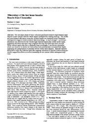
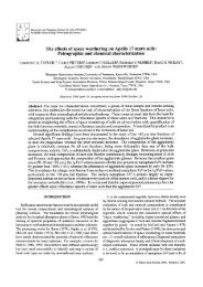
E11005JOZWIAK ET AL.: FLOOR-FRACTURED CRATER DISTRIBUTION AND ORIGINE11005Table 1. List of the Defining Characteristics for Each Class of FFC aCrater ClassClass Characteristics1 Deep floor, radial/concentric fractures, crescent shaped patches of marematerial along walls, central peak complexes2 Well-defined wall scarp, uplifted central region/convex up floor profile,concentric fractures3 Wide moat between crater wall scarp <strong>and</strong> crater interior, radial/polygonalfractures, terracing on wall opposite the nearby mare4aV-shaped moat, radial/concentric fractures, convex up floor profile4bV-shaped moat with pronounced inner ridge on the interior side, subtlefractures, irregular convex up floor profile4cV-shaped moat, hummocky interior5 Degraded crater walls, radial/polygonal fractures6 Mare-flooded interiors, concentric fracture pattern near walla Craters in each class need not possess all of the listed characteristics, although they must possess a majority in order to be classified.classification scheme of Schultz [1976], 2) provide morequantitative data on crater morphometry, 3) assess the globaldistribution of FFCs <strong>and</strong> members of their subclasses, <strong>and</strong> 4)revisit <strong>and</strong> reassess theories of origin (e.g., viscous relaxationor magmatic intrusion <strong>and</strong> piston-like uplift). The proposedtheories of origin predict different end-member morphologies,such as the height of the crater rim crest, although it is difficultto distinguish the processes by purely quantitative st<strong>and</strong>ards,because the exact amount of deformation experienced mayvary widely by crater. We first describe the classificationscheme of Schultz [1976], outline the major theories of origin,describe the data sets used in our analyses, <strong>and</strong> then addressthe four goals outlines above.1.1. Classification Scheme of Schultz [1976][4] Although FFCs share broad characteristics, they can bereadily divided into subcategories based on their morphology;Schultz [1976] described six subcategories for FFCs.We found these categories to be accurate classifications, <strong>and</strong>employ the descriptions when classifying FFCs. A summaryof subclass characteristics is presented in Table 1.[5] Class 1 (Figures 1 <strong>and</strong> 10i): Generally large craters—diameters between 50 km <strong>and</strong> 300 km with an average of140 km—with deep floors, central peak complexes, <strong>and</strong>extensive wall terraces. The floor has either radial or concentricfractures, or both. Among the defining characteristicsare crescent-shaped mare deposits that often occur along theedge of the crater wall scarp. Figure 1 highlights the characteristics<strong>and</strong> distribution of Class 1 FFCs as demonstratedby the crater Humboldt. Examples of Class 1 craters includeHumboldt (Figure 10i), Atlas, Schülter, <strong>and</strong> Cardanus.[6] Class 2 (Figures 2 <strong>and</strong> 10g): These craters are mid-sizecraters—diameters between 13 km <strong>and</strong> 75 km with an averageof 35 km—with a well-defined wall scarp <strong>and</strong> a convex-upfloor profile with an uplifted central floor. The most definingcharacteristic is the series of strong concentric featurescomprised of wall terraces <strong>and</strong> floor fractures. Figures 2a <strong>and</strong>10g show the Class 2 FFC characteristics displayed by thecrater Vitello. Examples of Class 2 craters include Vitello,Encke, <strong>and</strong> Davy.[7] Class 3 (Figures 3, 10a, <strong>and</strong> 10c): Class 3 craters varygreatly in size—diameters between 12 km <strong>and</strong> 170 km,however a majority have diameters between 30 <strong>and</strong> 60 km—but all have a wide moat feature separating the wall terracesfrom the central crater floor. The fractures in these cratersare either polygonal or radial in nature, <strong>and</strong> do not extendinto the moat region. Wall slumps <strong>and</strong> terraces may be present,<strong>and</strong> are generally located on the area of the crater farthestaway from the basin interior; correspondingly, the moat isoften deepest <strong>and</strong> most visible on the side of the crater closestto the basin (Figure 3b). The interior of the crater has a centralpeak complex <strong>and</strong> is covered with hummocky material,excepting parts of the moat which may contain mare units.There is a small subset of Class 3 craters that are locatedinside the mare units of a basin, <strong>and</strong> lack central peaks, floorfractures, <strong>and</strong> hummocky material; however, they have distinctlyshallow, flat floors <strong>and</strong> wide, pronounced moats.These craters exhibit a steeper wall slope than Class 3 FFCsnot located inside mare units, <strong>and</strong> their uplifted central regionis more pronounced. Figure 3a illustrates the Class 3 FFCcharacteristics in crater Gassendi. Examples of Class 3 cratersinclude Gassendi (Figure 10a), Taruntius (Figure 10c),Lavoisier; craters Haldane <strong>and</strong> Runge are examples ofthe wide-moat-mare subset.[8] Class 4a (Figure 4): Class 4 is divided into 3 subcategories—4a, 4b, <strong>and</strong> 4c—all class 4 craters possess ashallow “v” profile moat separating the wall scarp from thecrater interior. Class 4a has a less pronounced “v” moat <strong>and</strong>very low bounding inner ridge, <strong>and</strong> diameters between 4 km<strong>and</strong> 38 km, with a majority of diameters between 10 km <strong>and</strong>20 km. These craters have strong radial <strong>and</strong> concentricfractures across a hummocky floor that is generally convexup in profile. Class 4a is similar to Class 2, but distinguishedby the “v” moat, radial fractures, <strong>and</strong> more diffusewall scarps. Examples of Class 4a are Bohnenberger <strong>and</strong>Airy; Figure 4a depicts the Class 4a characteristics of craterBohnenberger.[9] Class 4b (Figures 5 <strong>and</strong> 10e): Craters in this categoryare between 7 km <strong>and</strong> 45 km in diameter, with an averagediameter of 25 km. They are dominated by a pronounced “v”moat <strong>and</strong> a high inner ridge; this inner ridge is often as highas the crater rim crest, <strong>and</strong> in cases such as Gaudibert(Figures 5a <strong>and</strong> 10e), the ridge is more prominent than theactual crater rim crest. The rim slope (between the rim <strong>and</strong>the inner ridge) is steeper than in Class 4a or 4c craters, aresult likely related to the greater height of the inner ridge inClass 4b FFCs. The interior of Class 4b craters is hummocky<strong>and</strong> may contain subtle radial fractures; the combination ofa high moat ridge <strong>and</strong> hummocky interior yield a ruggedinterior. Examples of Class 4b craters are Gaudibert(Figure 10e) <strong>and</strong> Stoney; Figure 5a illustrates the Class 4bcharacteristics of Gaudibert.2of23
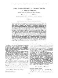
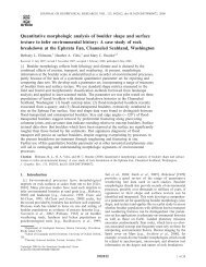
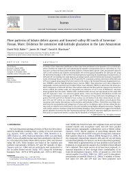
E11005JOZWIAK ET AL.: FLOOR-FRACTURED CRATER DISTRIBUTION AND ORIGINE11005Figure 1. Class 1 floor-fractured craters. (a) Crater Humboldt shown with LOLA topography overlainwith LROC-WAC image data. Distinguished as a Class 1 FFC by the dark patches of mare material alongthe wall, <strong>and</strong> the radial <strong>and</strong> concentric floor fractures. (b) Transect of Humboldt, indicated by the line fromA-A′ in Figure 1a. Marked on the profile are the locations of the class 1 FFC features. (c) Size-frequencyof Class 1 FFCs, binned by diameter; Class 1 FFCs are among the largest. (d) Areal distribution ofClass 1 FFCs.[10] Class 4c (Figure 6): Although alluded to by Schultz[1976], these types of craters were not previously a separatecategory of FFC. We find, however, that the class is differentenough from 4a <strong>and</strong> 4b to merit its own sub-category.The diameters of class 4c craters range from 8 km to 39 kmwith an average diameter of 15 km. In a manner similarto other class 4 craters, 4c craters contain a “v” shaped moat,but beyond this similarity, their characteristics are different.3of23
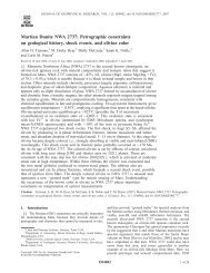
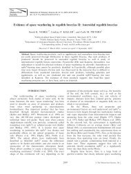
E11005JOZWIAK ET AL.: FLOOR-FRACTURED CRATER DISTRIBUTION AND ORIGINE11005Figure 2. Class 2 Floor-fractured craters. (a) Crater Vitello shown with LOLA topography overlain withLROC-WAC image data. Class 2 distinguishing features include the strong concentric fractures <strong>and</strong> theuplifted central region. (b) Transect of Vitello, indicated by the line from A-A′ in Figure 2a. Marked onthe profile are the locations of class 2 FFC features, note also the smooth transition between crater wall<strong>and</strong> crater floor, <strong>and</strong> the uplifted central crater region. (c) Size-frequency distribution of Class 2 FFCsbinned by diameter, like a majority of the FFC population, they range between 10 <strong>and</strong> 50 km in diameter.(d) Areal distribution of Class 2 FFCs.4of23
E11005JOZWIAK ET AL.: FLOOR-FRACTURED CRATER DISTRIBUTION AND ORIGINE11005Figure 3. Class 3 floor-fractured craters. (a) Crater Gassendi shown with LOLA topography overlainwith LROC-WAC image data. Class 3 is distinguished by a flat, plate-like floor, a wide moat, <strong>and</strong>radial/polygonal fractures. (b) Transect of Gassendi, indicated by the line from A-A′ in Figure 3a. Markedon the profile are the locations of class 3 FFC features, note in Gassendi the terracing on the crater wallopposite the basin, <strong>and</strong> the pronounced moat on the crater wall adjacent to the basin. (c) Size-frequencydistribution of Class 3 FFCs, although a wide range of diameters occur, the majority of Class 3 cratersare 30–40 km in diameter. (d) areal distribution of Class 3 FFCs; they are located almost exclusively justinside basins, or at basin margins.5of23
E11005JOZWIAK ET AL.: FLOOR-FRACTURED CRATER DISTRIBUTION AND ORIGINE11005Figure 4. Class 4a floor-fractured craters. (a) Crater Bohnenberger shown with LOLA topography overlainwith LROC-WAC image data. Class 4a is distinguished by a “v”-profile moat, radial or concentricfractures, <strong>and</strong> a convex-up crater floor. (b) Transect of Bohnenberger, indicated by the line from A-A′ inFigure 4a. Marked on the profile are the locations of class 4a FFC features, note despite the large fracturecutting through the center of the crater floor, the floor has an overall convex up profile. (c) Size-frequencydistribution of Class 4a FFCs. (d) Areal distribution of Class 4a FFCs; note that Class 4a FFCs are moreuniformly located beyond basin margins, <strong>and</strong> into the lunar highl<strong>and</strong>s.6of23
E11005JOZWIAK ET AL.: FLOOR-FRACTURED CRATER DISTRIBUTION AND ORIGINE11005Figure 5. Class 4b floor-fractured craters. (a) Crater Gaudibert shown with LOLA topography overlainwith LROC-WAC image data. Class 4b is distinguished by a “v”-profile moat with a very pronouncedinner ridge occasionally higher than the crater rim crest, a hummocky convex up central floor region,<strong>and</strong> subdued fractures. (b) Transect of Gaudibert, indicated by the line from A-A′ in Figure 5a. Markedon the profile are the locations of class 4b FFC features, note how the ridge nearly matched the elevationof the crater rim crest. (c) Size-frequency distribution of Class 4b craters. (d) Areal distribution of Class 4bFFCs, as with Class 4a, they are located farther from the basin margins than Class 3 FFCs.7of23
E11005JOZWIAK ET AL.: FLOOR-FRACTURED CRATER DISTRIBUTION AND ORIGINE11005Figure 6. Class 4c floor-fracture craters. (a) Unnamed crater located at 56.3 S, 143.9 W shown withLOLA topography overlain with LROC-WAC image data. Class 4c is distinguished by a “v”-profile moat,although the interiors vary between craters, <strong>and</strong> floors can be either convex up or concave down in profile.(b) Transect of the crater located at 56.3 S, 143.9 W, indicated by the line from A-A′ in Figure 6a. Markedon the profile are the locations of class 4c FFC features. (c) Size-frequency distribution of Class 4c craters,the vast majority having diameters 10–20 km. (d) Areal distribution of Class 4c FFCs.8of23
E11005JOZWIAK ET AL.: FLOOR-FRACTURED CRATER DISTRIBUTION AND ORIGINE11005The interiors are shallower than fresh craters, <strong>and</strong> appearflat, although most have a slightly concave up floor profile.The surface is hummocky <strong>and</strong> largely lacking fractures.The texture of the floor varies between craters, but theyare united by evidence of post emplacement modification.Class 4c craters are often small <strong>and</strong> unnamed, <strong>and</strong> occasionallydifficult to identify as craters. A named example of aClass 4c crater is Colombo M, the Class 4c characteristics ofthe crater located at 56.3S, 143.9W are shown in Figure 6a.[11] Class 5 (Figure 7): Class 5 craters are old, degradedcraters with strong radial, concentric, <strong>and</strong>/or polygonal fracturescutting their floors; they have diameters ranging from12 km to 177 km, with the vast majority between 45 km <strong>and</strong>100 km. The interiors of these craters are old highl<strong>and</strong>material, <strong>and</strong> often contain slumps from the degraded walls.Like the rest of the crater, the rim crest is heavily degraded.Examples of Class 5 craters include Von Braun, Repsold,<strong>and</strong> Alphonsus. Figure 7a shows the Class 5 features of craterVon Braun.[12] Class 6 (Figure 8): Class 6 craters are easily identifiedby their distinctive interiors which are completely floodedby mare material; excluding the extreme diameters of 5 km<strong>and</strong> 700 km, Class 6 FFC diameters range between 50 km<strong>and</strong> 200 km. Additionally, Class 6 craters have a distinctiveconcentric fracture pattern close to their wall scarp. Somecraters have central peaks <strong>and</strong> radial fractures, although theseare not requirements. Examples of Class 6 craters includePitatus <strong>and</strong> Fracastorius, <strong>and</strong> the Class 6 features of craterPitatus are shown in Figure 8.1.2. Theories of Origin of FFCs[13] There are currently two proposed formation mechanismsfor FFCs: magmatic intrusion leading to sill formation[Brennan, 1975; Schultz, 1976; Wichman <strong>and</strong> Schultz, 1995]<strong>and</strong> viscous relaxation [Masursky, 1964; Daneš, 1965;Cathles, 1975; Schultz, 1976; Hall et al., 1981; Dombard<strong>and</strong> Gillis, 2001]. The process of magmatic intrusion hasbeen modeled by Johnson <strong>and</strong> Pollard [1973], a schematicfor this process is shown in Figure 9. Energy from the initialcrater impact forms a highly fractured region <strong>and</strong> brecciatedlens beneath the crater [Baldwin, 1963; Roddy, 1968;Roddy, 1977]. A magma filled crack (dike) propagates upwardfrom the magma source region in the mantle [Wilson <strong>and</strong><strong>Head</strong>, 1981]. When the propagating dike reaches this level,it ceases vertical propagation <strong>and</strong> begins to spread laterally.The magma then spreads beneath the crater forming an axisymmetricsill broadly consistent with the dimensions of thecrater floor. The sill then begins to grow vertically, upliftingthe overlying crater floor; eventually the pressure becomessufficient to cause piston-like uplift of the crater floor.Depending on the extent of the intrusion, additional faults,graben, <strong>and</strong> mare units may be formed on the crater walls<strong>and</strong> floor [Schultz, 1976].Schultz [1976] examines this proposedprocess extensively, <strong>and</strong> shows models for increasingamounts of crater modification in response to a growingintrusion, including the formation of graben <strong>and</strong> terraces <strong>and</strong>the floor fractures observed in the craters.[14] On the other h<strong>and</strong>, the shallow crater floors <strong>and</strong> floorfractures could be the result of viscous relaxation, sketchedin Figure 9b. Viscous relaxation occurs when high thermalgradients within a given region lead to a decrease in materialstrength <strong>and</strong> a corresponding relaxation in the regionaltopography, particularly the long-wavelength topography[Daneš, 1965; Baldwin, 1968; Cathles, 1975; Hall et al.,1981; Dombard <strong>and</strong> Gillis, 2001]. In the most basic system,that which assumes constant Newtonian viscosity, viscositydecreases with depth (a result of temperatureincreasing with depth), <strong>and</strong> as a result, long wavelength features,such as the crater depression, tend to relax; this resultsin an apparently shallower crater depth <strong>and</strong> an upbowed floor[Parmentier <strong>and</strong> <strong>Head</strong>, 1981; Hall et al., 1981; Solomonet al., 1982; Dombard <strong>and</strong> Gillis, 2001]. The lunar crustcan also be modeled as an extended Maxwell solid whoserheology has three components: linear elasticity (as seen inconstant Newtonian viscosity models), solid state ductilecreep, <strong>and</strong> plasticity [Albert et al., 2000]. Modeling the cratersystem using this more complex elastoviscoplastic relaxationprocess, results in the same relaxed topography <strong>and</strong> bowedfloor as seen previously, but with the addition of floor fractures.These floor fractures are the result of a cold shallowcrust containing the crater overriding warmer, less viscousdeeper material. The system strain created by this situationleads to upward flexure of the bottom of the crater floor,<strong>and</strong> this flexure causes bending stresses on the crater floorthat may yield floor fractures [Dombard <strong>and</strong> Gillis, 2001].Both the Newtonian viscosity model [Parmentier <strong>and</strong> <strong>Head</strong>,1981; Hall et al., 1981; Solomon et al., 1982; Dombard <strong>and</strong>Gillis, 2001] <strong>and</strong> elastoviscoplastic model [Dombard <strong>and</strong>Gillis, 2001] have been used to model the effects of viscousrelaxation on craters, but are limited by the accuracy of inputparameters describing the lunar rheology, <strong>and</strong> the assumptionof axisymmetric deformation.[15] A problem arises then in determining which of thesemechanisms formed floor-fractured craters, as both mechanismsare predicted to produce the large-scale characteristicfeatures of the craters. Our study uses the new high-resolutiontopographic <strong>and</strong> image data from the Lunar Orbiter LaserAltimeter (LOLA) <strong>and</strong> Lunar Reconnaissance Orbiter Camera-Wide-angle Camera (LROC-WAC), respectively, to analyzethe smaller-scale characteristics that define the differentclasses of FFC, <strong>and</strong> also to characterize <strong>and</strong> plot the distributionof these classes on the lunar surface. This distribution,<strong>and</strong> the high-resolution data allow us to investigate in a newway the formation of FFCs, in particular the ability of theproposed theories to explain the distribution of FFC types,<strong>and</strong> the more detailed differences in addition to the fundamentaldifferences from fresh craters illustrated by theirshallow floors <strong>and</strong> floor-fractures.2. Data Set <strong>and</strong> Analysis of FFCs[16] The data used in this analysis were drawn from LOLA<strong>and</strong> LROC-WAC data sets. The LOLA data set that servedas a global lunar base map was composed of tiles at 512 m/pixel resolution. This basemap was overlaid with a hillshadegenerated from the 512 m/pixel LOLA data, <strong>and</strong> LROC-WAC imagery. The craters Humboldt (1), Vitello (2), Gassendi(3), Bohnenberger (4a), Gaudibert (4b), Von Braun (5), <strong>and</strong>Pitatus (6) were identified as exemplary for their class (listedin parentheses), because they contained all or a majority ofthe defining characteristics for their specific class. Profiles ofthese craters (Figures 1b 2b, 3b, 4b, 5b, 6b, 7b, <strong>and</strong> 8b) werecompiled from the gridded data to investigate the variationsin crater morphometry between FFCs <strong>and</strong> fresh craters9of23
E11005JOZWIAK ET AL.: FLOOR-FRACTURED CRATER DISTRIBUTION AND ORIGINE11005Figure 7. Class 5 floor-fractured craters. (a) Crater Von Braun shown with LOLA topography overlainwith LROC-WAC image data. Class 5 is distinguished by a flat plate-like floor, radial or polygonalfractures, <strong>and</strong> an old, degraded appearance. (b) Transect of Von Braun, indicated by the line fromA-A′ in Figure 7a. Marked on the profile are the locations of Class 5 FFC features, note the extremely flatfloor <strong>and</strong> prevalent wall slumps. (c) Size-frequency distribution of Class 5 craters, a large span of diametersare present, <strong>and</strong> are mostly larger than a majority of FFCs. (d) Areal distribution of Class 5 FFCs, notelocations close to basin margins, in particular to the west of Oceanus Procellarum.10 of 23
E11005JOZWIAK ET AL.: FLOOR-FRACTURED CRATER DISTRIBUTION AND ORIGINE11005Figure 8. Class 6 floor-fractured craters. (a) Crater Pitatus shown with LOLA topography overlain withLROC-WAC image data. Class 6 is distinguished by a mare-flooded interior <strong>and</strong> a concentric fracturepattern near the crater wall. (b) Transect of Pitatus, indicated by the line from A-A′ in Figure 8a. Markedon the profile are the locations of Class 6 FFC features. (c) Size-frequency distribution of Class 6 FFCs,which are larger than average FFCs. (d) Areal distribution of Class 6 FFCs, note proximity to basins.(Figure 10), as well as between FFC classes. The results ofthese analyses are described in the following section. A globalsearch for FFCs was undertaken using the LROC <strong>and</strong> LOLAdatabases. An initial list of currently recognized FFCs wascompiled using the global distribution map of Schultz [1976];this list was then used as a guide for corroboration of thecurrently identified FFCs <strong>and</strong> identification of any previouslyunidentified FFCs found in our global search. We identified11 of 23
E11005JOZWIAK ET AL.: FLOOR-FRACTURED CRATER DISTRIBUTION AND ORIGINE11005approximately 10–20 previously unnoted FFCs, <strong>and</strong> removedapproximately 10 from the existing lists because the LOLA<strong>and</strong> LROC data showed that the craters did not share thecharacteristics of FFCs. Using the LOLA <strong>and</strong> LROC-WACglobal data, craters were located, <strong>and</strong> those that fit the characteristicsof FFCs were recorded in a newly generated list ofall lunar FFCs, provided as auxiliary material to this paper. 1The morphology of individual craters was studied in detailusing both LOLA altimetry <strong>and</strong> LROC Narrow-Angle Camera(NAC) image data. These analyses were all carried outusing the ArcGIS program platform.2.1. Floor-Fractured Crater Diameter Distribution<strong>and</strong> Morphometry[17] The diameter frequency distribution of FFCs(Figures 1c, 2c, 3c, 4c, 5c, 6c, 7c, <strong>and</strong> 8c) highlights thepredominance of FFCs with diameters between 10 km <strong>and</strong>40 km. This could have implications for the preferentialscale of activity for the FFC formation mechanism. Currentgravity data resolution cannot define gravity anomalies inareas as small as a majority of these craters. However,GRAIL (Gravity Recovery <strong>and</strong> Interior Laboratory) missiondata will acquire data at this scale, <strong>and</strong> could reveal theformation mechanism, as will be discussed in section 3.3.[18] For detailed morphologic <strong>and</strong> morphometric characterization,a representative crater was selected from each FFC1 Auxiliary materials are available in the HTML. doi:10.1029/2012JE004134.class (Figure 10); these craters were selected because theycontained all of the identifying characteristics of their class,thus providing an end-member example for each class, <strong>and</strong>assisting comparisons between classes. These representativeFFCs were then compared to Copernican-aged cratersFigure 9. Diagrammatic cross-sectional representations ofa fresh complex crater <strong>and</strong> the predictions of two c<strong>and</strong>idatecrater modification processes proposed to explain the characteristicsof floor-fractures craters. (a) Fresh complex cratersare characterized by a depth-diameter (d/D) relationship ofapproximately d = 1.044D 0.301 [Pike, 1980], <strong>and</strong> an exteriorrim crest height (h) that represents the height of the craterrim crest above the level of the surrounding uncratered substrate.Exterior crater rim crest height is a combination ofstructural uplift <strong>and</strong> ejecta thickness <strong>and</strong> is represented in thisdiagram by a horizontal dashed line labeled ORCH (originalrim crest height) for reference in b <strong>and</strong> c. The cater interior ischaracterized, from the rim crest inward, by wall terracesformed by rim slumping in the terminal stages of the crateringevent, impact melt overlying a breccia lens emplaced in theterminal stages of the impact event as impact melt settled tothe crater floor above the breccias lens, <strong>and</strong> a central peak,uplifted <strong>and</strong> emplaced in the latter part of the excavation <strong>and</strong>modification phase. (b) Complex craters undergoing viscousrelaxation [e.g., Hall et al., 1981; Dombard <strong>and</strong> Gillis, 2001]experience a wavelength-dependent change in topography.Long-wavelength topography (in this case, at the scale of thecrater itself) decreases in amplitude, while short-wavelengthtopography, such as the central peaks of the shape of the rimcrest itself, is much less affected. This results in an overalldecrease in the depth of the crater (d) <strong>and</strong> a decrease in the originalrim crest height (ORCH), as the original crater topographysmooths out at long wavelengths. Local (short-wavelength)topographic features, such as the central peaks <strong>and</strong> the craterrim crest tend to remain prominent, however. Evidence for afresh complex crater undergoing viscous relaxation (Figure 9b)would be a decrease in both the crater depth (d) <strong>and</strong> the craterexterior rim crest elevation (h), <strong>and</strong> a distinctive crater interiortopographic profile [e.g., Dombard <strong>and</strong> Gillis, 2001]. (c) Floorfracturedcraters have also been interpreted as complex cratersintruded by dikes <strong>and</strong> sills [e.g., Schultz, 1976; Wichman <strong>and</strong>Schultz, 1996]. In this scenario, a dike propagating verticallyfrom the mantle toward the surface encounters a low-densitybreccias zone at the base of the crater floor, becomes neutrallybuoyant [see <strong>Head</strong> <strong>and</strong> Wilson, 1992], <strong>and</strong> spreads laterally toform a sill. Continued pressurization of the sill causes verticalthickening <strong>and</strong> uplift of the crater floor <strong>and</strong> central peaks, withthe most extreme deformation focused at the lateral margins ofthe sill. The predicted result of sill emplacement is the fracturing<strong>and</strong> faulting at the margins of the crater floor, uplift of thefloor <strong>and</strong> central peaks (with some associated floor deformation),formation of a marginal trough or moat as the crater flooris elevated above the base of the wall terraces, <strong>and</strong> a decreasein the value of (d), the depth to the crater floor. In the sill intrusionmodel, the exterior rim height, h, should remain unaltered.These predictions of the behavior of complex impact craters(Figure 9a) that have undergone either viscous relaxation(Figure 9b), or sill intrusion <strong>and</strong> floor uplift (Figure 9c), canbe used to distinguish the origin of floor-fractured cratersusing new image <strong>and</strong> altimetry data.12 of 23
E11005JOZWIAK ET AL.: FLOOR-FRACTURED CRATER DISTRIBUTION AND ORIGINE11005Figure 10. LROC-WAC images of Floor-Fractured craters <strong>and</strong> the Copernican-aged, un-modified impactcraters they were compared against. (a) Crater Gassendi compared against (b) Crater Tycho; (c) CraterTaruntius compared against (d) Crater Aristillus; (e) Crater Gaudibert compared against (f) Crater Kepler;(g) Crater Vitello compared against (h) Crater Glushko; (i) Crater Humboldt compared against (j) CraterHausen (Eratosthenian-aged).(Figure 10), with diameters comparable to the diameters ofthe selected FFCs. The motivation for this comparison wastwofold: 1) to quantify the morphologic differences betweenFFCs <strong>and</strong> normal fresh craters to assess the differences <strong>and</strong>their geographic locations at the craters, <strong>and</strong> 2) to use thesedata to help determine the formation mechanism of FFCs.Copernican craters were used because they represent theyoungest lunar craters [Wilhelms, 1987], <strong>and</strong> as such haveundergone the least deformation <strong>and</strong> modification, <strong>and</strong> forthe purposes of comparison can be used to represent freshimpact craters.13 of 23
E11005JOZWIAK ET AL.: FLOOR-FRACTURED CRATER DISTRIBUTION AND ORIGINE11005Figure 11. Plot of frequency of floor depth for craters(a) Gassendi, a FFC, <strong>and</strong> (b) Tycho, an un-modified impactcrater. In Figure 11a, Gassendi is a Class 3 FFC <strong>and</strong> has amuch broader spectrum of frequent floor depths, indicatinga floor that is wider <strong>and</strong> flatter than the floor of crater Tycho(Figure 11b). Tycho displays narrow b<strong>and</strong>s of frequent floordepths corresponding to the classical bowl-like shape ofimpact craters.[19] Crater diameter was calculated using a 3-point circlefit. On each crater, three points were selected on the rim crest<strong>and</strong> then used to form a circle. The selected points werespaced in equidistant locations on the rim crest around thecrater; the points were also selected to avoid areas where thecrater wall or rim crest had been modified by post-impactevents, such as additional crater impacts on the rim. Mostof the craters were not perfectly circular, so to accountfor this, each crater was fit three times, <strong>and</strong> the average ofthese fits was taken as the crater diameter.[20] Given the precision of LOLA data, 30 m spatialresolution <strong>and</strong> 1 m vertical resolution [<strong>Smith</strong> et al., 2010;<strong>Zuber</strong> et al., 2010], detailed crater floor depth measurementswere made. In each crater, profiles were taken from rim crestto rim crest trending west- east, northwest-southeast, <strong>and</strong>southwest-northeast; these data were compiled <strong>and</strong> a depthfrequency plot was constructed with depths binned in 25 mintervals. Although the plots showed significant variation inshape between Copernican craters <strong>and</strong> FFCs, in both casesthe most frequent floor depth was used to represent theaverage floor depth for the crater. Copernican craters such asTycho have a narrow frequency peak at the deepest depthscorresponding to their crater floor (Figure 11b), <strong>and</strong> in manycases the deepest floor depth was also the most frequent. InFFCs, however, there is a larger spread of depths for thecrater floor (Figure 11a). This spread arises from floor fractures,which expose small areas of greater depth, as well asoccasional wall slumps <strong>and</strong> convex floor profiles. To mitigatethese contributions, the most frequent floor depth wasused to represent the average floor depth.[21] Using ArcGIS, a line was traced along the entirety ofthe rim crest, a corresponding profile generated, <strong>and</strong> fromthis an elevation for the average rim crest height wasobtained. It should be noted that when tracing the rim crest,areas with post-impact modification to the rim crest, such assubsequent cratering, were omitted. From the terrain surroundingthe crater, profiles were taken to represent theaverage background elevation. This average elevation wasthen subtracted from the background elevation to yield theexterior rim crest height.[22] Crater classes were assigned using a combination ofqualitative <strong>and</strong> quantitative methods. Crater morphologywas the largest factor in crater classification. Craters displayeda majority of class-specific characteristics (Table 1) thatallowed them to be categorized. At times there is ambiguitybetween the morphologic characteristics of a crater, at whichpoint LOLA topography was used to generate detailed craterprofiles. These profiles resolved the crater classification, asthey revealed finer scale crater features that helped to distinguishbetween different classes, for example the presence ofa moat to distinguish between Class 2 (Figure 2) <strong>and</strong> Class 4(Figure 4).2.2. FFC <strong>and</strong> Fresh Crater Comparison[23] Floor Fractured Craters exhibit distinct morphologicdifferences from fresh impact craters. Many of the differencesare localized to the crater floor. All classes of FFCcontain fractures on their floors. The fractures vary in widthdepending on the crater class; the fractures also vary in orientation,<strong>and</strong> can be radial, concentric, or polygonal. Many ofthe fractures, especially the larger ones are interpreted to begraben.[24] Certain classes of FFC have moat features (Figures 3a,3b, 4a, 4b, 5a, 5b, 6a, <strong>and</strong> 6b) with Figure 12 depicting thisspecific type of morphologic feature. Wide moats (Figures 3a,3b, <strong>and</strong> 12a) are separated from the central crater floor byconcentric fractures or strong topographic differences.Topographically, the moats are either flat, or slope downtoward the wall scarp forming a broad “U” shape. Widemoats comprise, on average, 40% of the crater floor; althoughother crater morphologies, such as terraces, can decreasethe percent of floor coverage. Other craters have a narrowmoat feature that has a characteristic “v” shaped profile(Figures 4a, 4b, 5a, 5b, 6a, 6b, 12b, <strong>and</strong> 12c). This moat typeis identified in topographic profile by the “v” shape formedbetween the interior crater wall <strong>and</strong> the domed central craterfloor region. In Class 4b craters, this moat is bounded on theinside by a ridge (Figures 5b <strong>and</strong> 12c). The ridge varies inheight from almost indistinguishable from the elevation ofthe interior crater floor (Figures 4b, 6b, <strong>and</strong> 12b) to beingnear the height of the crater rim crest (Figure 5b). We note14 of 23
E11005JOZWIAK ET AL.: FLOOR-FRACTURED CRATER DISTRIBUTION AND ORIGINE11005Figure 12. LOLA topographic profiles depicting the range of FFC moat morphology. (a) Wide moatfrom crater Haldane. The interior of crater Haldane is has a visually distinct flat central region surroundedby a clear wide moat, indicated in the LOLA topographic profile. (b) “V” profile moat without an innerridge from crater Bohnenberger. Note how the meeting of the wall scarp <strong>and</strong> the domed central crater floorcreate a “v” shape, for which the “v” profile moat is named. (c) “V” profile moat with an inner ridge fromcrater Gaudibert. Crater Gaudibert hosts the most topographically distinct inner ridge, with the elevation ofthe inner ridge exceeding the crater rim crest in places. The “v” moat is created by the meeting of the craterwall with the ridge material.that not all Class 4a <strong>and</strong> 4c craters have a discernible ridgefeature; however, they do all have the “v” profile.[25] FFCs have distinctly broad, shallow floors, althoughthe floor can tend to be concave up (Figure 6b), concavedown (Figure 2b), or flat to irregular in topographic profile(Figures 3b <strong>and</strong> 7b). This is distinctly different from freshcraters which display the classic parabolic profile (Figure 11b)<strong>and</strong> do not have a distinct central floor region except centralpeaks at larger diameters.15 of 23
E11005JOZWIAK ET AL.: FLOOR-FRACTURED CRATER DISTRIBUTION AND ORIGINE11005Figure 13. Depth versus diameter relationship for FFCs plotted with the same relationship for freshimpact craters. The craters used are shown in Figure 9. Note the distinctly shallower trend for FFC depths.[26] This fundamental difference in crater floor interiorbetween fresh craters <strong>and</strong> FFCs is readily observed in floordepth versus frequency distributions as shown in a comparisonof the depth frequency distributions for FFC Gassendi, <strong>and</strong>the Copernican-aged crater Tycho (Figure 11). Fresh craterdepth distributions (Figure 11b) show a frequency spikecorresponding to the crater rim crest, a small one at the centralpeak (if present), <strong>and</strong> then a large spike at the deepest floordepth. On rare occasion there are a few depths deeper than themost frequent depth, however, they are negligible by comparison.FFC crater depth distributions (Figure 11a), on theother h<strong>and</strong>, display the spikes at the rim crest height <strong>and</strong>central peak, but have a spread of very frequent depths, withthe most frequent values corresponding to the broad upliftedcentral crater floor depth. There is a significant frequency ofdepths deeper than the most frequent one, <strong>and</strong> these depthscome from the interior of the fractures <strong>and</strong> also the moatspresent in certain classes.[27] Comparison of the fresh (Tycho) <strong>and</strong> floor fractured(Gassendi) craters (Figure 11) also readily shows that therange of depths is very different, with Tycho having almosttwice the topographic range as Gassendi. Indeed, the newdata confirm that FFCs typically differ from fresh impactcraters in their depth to diameter ratio (Figure 13). Pike[1980] demonstrated a relationship between crater diameter<strong>and</strong> crater depth for lunar craters (red squares in Figure 13).FFCs are shallower than fresh craters, <strong>and</strong> thus follow ashallower regression when depth is plotted against diameter(blue diamonds in Figure 13). This was noted by Schultz[1976], <strong>and</strong> is corroborated by the LOLA data measured(Figure 13). We also investigated the depth to diameter ratiofor individual FFC classes, plotting approximately 70%of the craters for each class. All classes had a shallowerregression than would be predicted by Pike [1980]; however,there were no observable trends beyond this shallowerrelationship. We make these data available in the auxiliarymaterial.[28] Pike [1980] also documented a relationship betweencrater diameter <strong>and</strong> exterior crater rim crest height in freshcraters (red squares in Figure 14). FFCs plot along this sameregression (blue diamonds in Figure 14), demonstrating thatthe modification to FFCS occurred primarily to their floor,not their rim (compare Figures 11a <strong>and</strong> 11b <strong>and</strong> Figures 13<strong>and</strong> 14). This relationship holds true even for FFCs with aninner ridge, such as Class 4b, demonstrating further that themodification occurs primarily in the central floor region ofthe crater.2.3. FFC Areal Distribution[29] A plot of the entire population of FFCs on the lunarsurface (Figure 15) shows that the majority of FFCs arelocated in close vicinity to the lunar maria <strong>and</strong> the mare-filledimpact basins, with a significant population also located inthe South Pole Aitken basin, <strong>and</strong> in the highl<strong>and</strong>s, especiallythe highl<strong>and</strong>s west of Oceanus Procellarum. This distributionwas also noted by Schultz [1976] but the distribution of thesubclasses was not given there. We will examine the distributionof individual FFC classes <strong>and</strong> use this as a basis toassess further the proposed formation mechanisms.[30] Class 1 FFCs (large craters with radial <strong>and</strong> concentricfractures, <strong>and</strong> wall- adjacent patches of mare material)(Figure 1d) do not constitute a large population (8 craters),<strong>and</strong> with one exception, are not located directly adjacentto basins. This location away from direct basin edge contactis intriguing given that the hallmark of Class 1 FFCs arethe patches of mare material along the crater wall margins(Figure 1a). This supports the hypothesis that the Class 1FFCs were formed by magmatic intrusion as opposed toviscous relaxation, if the mare patches are areas where theintruding magma reached the surface.[31] Class 2 FFCs (medium size craters with strong concentricfractures <strong>and</strong> convex up floor profiles) (Figure 2d)are located along the edges of maria <strong>and</strong> basins, with a fewalso located inside the South Pole Aitken (SPA) basin. Thereis no apparent correlation between the age of the FFC <strong>and</strong>the age of the basins. The distinguishing feature of Class 2craters, concentric fractures around an uplifted central region(Figure 2b), can be explained as uplift caused by either magmaticintrusion or viscous relaxation. There are five Class 2FFCs located in highl<strong>and</strong> regions. Several of these resembleClass 4 FFCs, however, lack the “v” shaped moat (compareFigure 2b with Figure 5b). It is unclear if this is a reflection16 of 23
E11005JOZWIAK ET AL.: FLOOR-FRACTURED CRATER DISTRIBUTION AND ORIGINE11005Figure 14. External rim crest height versus diameter relationship for FFCs plotted with the samerelationship for fresh impact craters. The crater populations used are shown in Figure 9. Note both FFC<strong>and</strong> fresh crater populations follow the same trend.of different formation mechanisms, or simply a difference inhow the mechanism manifests itself in different lunar regionsor substrates.[32] Class 3 FFCs (wide moat with a shallow floor <strong>and</strong>radial <strong>and</strong> polygonal fractures) (Figure 3d) are localizedto the edges <strong>and</strong> close interiors of basins <strong>and</strong> mare units.The distinguishing morphology of this class is a wide moat(Figures 3a <strong>and</strong> 3b); in craters located at the edges ofbasins, the moat is more pronounced on the basin interior side(Figures 3a <strong>and</strong> 3b), <strong>and</strong> occasionally contains mare units.Proximity of these craters to large impact basins couldimplicate a role for thermal processes linked to basin formation.Localized thermal anomalies associated with heat ofimpact <strong>and</strong> geotherm uplift in the short term basin modificationphase could create environments conducive to viscousrelaxation of subsequently formed craters [e.g., Hall et al.,1981]. The distribution of these FFCs, however (Figure 3a),indicates that they form adjacent to basins with a wide rangeof formation ages (e.g., Humorum, Nubium, Nectaris, Crisium,Imbrium, Serenitatis, etc.) [Fassett et al., 2012], <strong>and</strong> thus abasin-related thermal anomaly is unlikely to have persistedlong enough to retain regional geothermal fluxes sufficient toinfluence viscous relaxation of later craters [e.g., Bratt et al.,1985a, 1985b]. A more direct correlation is with the time ofemplacement of the actual mare deposits themselves [e.g.,Hiesinger et al., 2010].Figure 15. Areal distribution of all FFCs. FFCs tend to be located near mare-filled basins <strong>and</strong> impactbasin margins, although there is also a significant population located in the lunar highl<strong>and</strong>s. There is alsoa relationship between FFC class <strong>and</strong> location, as seen Figures 1d, 2d, 3d, 4d, 5d, 6d, 7d, <strong>and</strong> 8d.17 of 23
E11005JOZWIAK ET AL.: FLOOR-FRACTURED CRATER DISTRIBUTION AND ORIGINE11005Figure 16. Percent relaxation of a crater undergoing viscousrelaxation, as a function of diameter <strong>and</strong> time, modeled underreasonable lunar thermal conditions. Little to no relaxationoccurs for craters under 80 km diameter, a majority ofFFCs, <strong>and</strong> at the longest timescales craters modeled withthe largest diameter experience less than 10% relaxation.(From Dombard <strong>and</strong> Gillis [2001].)[33] Class 4a FFCs (small craters with “V” profile moat<strong>and</strong> radial or concentric fractures) (Figure 4d), are the mostnumerous of Class 4 craters. They are located generally nearmare basin margins, although as in cases such as west ofOceanus Procellarum, they are not necessarily at the edgesof an impact basin. There is also a significant populationof 4a FFCs scattered throughout the highl<strong>and</strong>s. These craterscontain both a “v” shaped profile occasionally with a subtleinner ridge, <strong>and</strong> distinct radial <strong>and</strong>/or concentric floor fractures(Figures 4a <strong>and</strong> 4b). Uplift alone does not uniquely indicatea specific formation mechanism. However, the addition ofthe “v” profile (Figure 4b), suggests an area that may bedefined by a subsurface magmatic intrusion that uplifted thecentral region of the crater, producing the “v” shaped moat inthe uplift process. Long wavelength viscous relaxation mightfavor more subtle topographic variations.[34] Similar to Class 4a, Class 4b (small craters with “V”profile moat, a pronounced inner ridge, <strong>and</strong> subdued fractures)(Figure 5d) craters are located primarily away from impactbasins; indeed Class 4b craters are found to the outside ofClass 4a craters relative to mare-filled basins, suggesting arelationship of Class 4a craters <strong>and</strong> Class 4b craters as a functionof increasing distance from an impact basin. The distinguishingmorphologic features of 4b craters (Figure 5a) arethe pronounced “v” profile moat (Figure 5b), a very high innerbounding ridge (Figure 5b), <strong>and</strong> a hilly interior with subtleradial fractures (compare Figure 5b with other class profiles).If we postulate that Class 4b craters (Figure 5) are simplya spatial evolution of Class 4a craters (Figure 4), the differentmorphology could be a result of thicker crust, warping <strong>and</strong>muting the effects of the magmatic intrusion. At the same time,the generally muted <strong>and</strong> sinuous topography of 4b craterscould be a result of deformation by viscous relaxation.[35] Class 4c (small craters with a “V” profile moat)(Figure 6d), is the only class in this study not distinctlyclassified or mentioned in the original Schultz [1976] classification.Craters of Class 4c are located away from the mare,though not necessarily deep in the lunar highl<strong>and</strong>s in a mannersimilar to some of the Class 4a craters (Figure 4d). As mentionedpreviously, the craters have varied morphology,although all share a nominal “v” profile moat, shallow floor,<strong>and</strong> a fractured <strong>and</strong>/or hilly textured interior (Figures 6a<strong>and</strong> 6b). There is nothing specific in their spatial distributionor morphology to favor formation by either viscous relaxationor magmatic intrusion.[36] Class 5 craters (degraded craters with radial <strong>and</strong>polygonal fractures) (Figure 7d) are numerous (32 craters),<strong>and</strong> a majority are located in the highl<strong>and</strong>s west of OceanusProcellarum, although in positions closer to the mare than theClass 4 craters in this region (Figure 4d). They are locatedthroughout highl<strong>and</strong>s north of Mare Crisium, <strong>and</strong> a scatteringof other places. The defining features of members of thisclass are their old, degraded appearance with strong radial<strong>and</strong> occasionally concentric fractures (Figures 7a <strong>and</strong> 7b).The degraded nature of the crater suggests an older age forthe host crater than other FFCs. The prevalence of thesecraters near, but not on, the edge of Oceanus Procellarumcould be indicative of a relationship between the modificationof these now Class 5 FFCs <strong>and</strong> the formation of OceanusProcellarum, or the emplacement of mare units in OceanusProcellarum [e.g., Hiesinger et al., 2010]. Although thehighly subdued features of the crater (Figure 7a) may be theresult of viscous relaxation, the generally flat floor profilesof Class 5 craters (Figure 7b) are not consistent with theflexure associated with viscous relaxation processes [Hallet al., 1981].[37] There is a small population of Class 6 FFCs (marefloodedinteriors with concentric fractures along the outeredge of the crater floor) (Figure 8d) <strong>and</strong> they are all locatedat the edge of a mare filled basin. This is not surprisingbecause Class 6 craters are defined by their smooth, mareflooded interiors (Figure 8a). The other identifying featureof these craters is their distinct concentric fracture patternaround the edge of the crater interior (Figures 8a <strong>and</strong> 8b).As with the other craters, this fracture pattern is not sufficientin itself to distinguish between a magmatic intrusionor viscous relaxation origin; their proximity to maria couldsuggest a formation mechanism involving magmatic processesor viscous relaxation due to the heat of basin formationor magmatic filling.3. Implications <strong>and</strong> Models for FFC Formation[38] In this section we present the major characteristicsof FFCs that might help to distinguish between an originby viscous relaxation <strong>and</strong> intrusion (Figures 16–19), <strong>and</strong>make further assessments to assist in this distinction.3.1. Formation Mechanism Implications of CraterMorphology <strong>and</strong> Morphometry3.1.1. Floor Depth[39] The key morphologic <strong>and</strong> morphometric feature ofFFCs is their shallow floor (Figures 11a, 11b, <strong>and</strong> 13), whichcould be produced by either viscous relaxation or magmaticintrusion. We compile in Table 3 the difference in the averagecrater depth <strong>and</strong> the theoretical depth of an unmodified crater18 of 23
E11005JOZWIAK ET AL.: FLOOR-FRACTURED CRATER DISTRIBUTION AND ORIGINE11005Figure 17. Half-space viscous relaxation model of CraterLal<strong>and</strong>e. As the model progressively shallows the floor ofthe crater, although it does not completely remove the craterrim crest, it does affect the elevation of the feature. Figure 12shows that FFCs <strong>and</strong> fresh craters have the same relationshipbetween rim crest height <strong>and</strong> diameter. Additionally, themodel does not produce a moat feature, a distinguishingcharacteristic of FFC classes 3, 4a, 4b, <strong>and</strong> 4c. (From Hallet al. [1981].)of that diameter [Pike, 1980]. These values could eitherbe interpreted as the amount of viscous relaxation or thepostulated intrusion thickness. Investigations into the amountof topographic relaxation necessary to reproduce craterFigure 19. Diagrammatic representation of crater modificationas a result of laccolith formation. D f is the crater floordiameter, used to represent the intrusion extent, <strong>and</strong> markedby either an uplifted region or the cohesive smooth craterfloor unit. W m is the thickness of the intrusion, taken to bethe difference of the observed FFC depth from the theoreticaldepth of an unmodified crater of the same size [Pike,1980]. T e is the effective flexural thickness of the floor asa result of the uplift, <strong>and</strong> the calculated values are listed inTable 3. H c is the length of the crustal magma column <strong>and</strong>d s is the length of the column past the Moho, although neitherparameter was used in the calculation of magma overpressure.r c <strong>and</strong> r m represent the crustal density <strong>and</strong> magma density,respectively. (From Wichman <strong>and</strong> Schultz [1995].)Figure 18. Sketch of post-impact crater structure for bothsimple <strong>and</strong> complex craters. The exact shape <strong>and</strong> nature ofthe fractured bedrock <strong>and</strong> impact breccias zone remainsunknown. (From Koeberl <strong>and</strong> Sharpton [2007].)shallowing have been undertaken by both Dombard <strong>and</strong>Gillis [2001] <strong>and</strong> Wichman <strong>and</strong> Schultz [1995]. Modelresults for percent crater relaxation as a function of craterdiameter under reasonable estimates of lunar conditions(Figure 15) show that the model predicts little to no shallowingover the range of FFC diameters. Dombard <strong>and</strong>Gillis [2001] conclude that “lunar crustal rocks are simplytoo rigid to have accommodated substantial relaxation overthe age of the Moon.”3.1.2. Exterior Rim Crest Height[40] The similarity of fresh crater <strong>and</strong> FFC exterior rimcrest heights (relative to external topography) is an additionalmorphologic feature that makes FFC formation due toviscous relaxation improbable. The process of viscous relaxationaffects primarily long wavelength topography, <strong>and</strong> thusthe crater floor; it also affects the elevation of the crater rimcrest, although this is not itself a long wavelength topographicfeature. Figures 13 <strong>and</strong> 14 show the depth versusdiameter <strong>and</strong> external rim crest height versus diameter,respectively, for both fresh craters <strong>and</strong> FFCs. The shallowerdepth versus diameter relationship combined with theunchanged rim crest height versus diameter relationship,demonstrate that the FFC modification process worked toshallow the floor without degrading any of the other crater19 of 23
E11005JOZWIAK ET AL.: FLOOR-FRACTURED CRATER DISTRIBUTION AND ORIGINE11005Table 2. Constants <strong>and</strong> Related Parameters Used in the Calculationof Intrusion Flexural Thickness, <strong>and</strong> Driving Pressure, Listed inTable 3 aSymbol Definition Assumed ValueE m Young’s Modulus (basalt) 7.03 *10 10 Pan Poisson’s Ratio 0.25B m Elastic Modulus of Country Rock, 7.47 *10 10 PaE/(1n 2 )k Magma Yield Strength 10 4 N/m2g Lunar gravitational acceleration 1.62 m/s 2r m Magma Density 2900 kg/m 3g m Unit Magma weight (r m g) 4700 kg/m 2 s 2a From Wichman <strong>and</strong> Schultz [1996].structure features. This morphology is more indicative ofthe piston-like uplift predicted by magmatic intrusion thanthe feature-muting predicted by viscous relaxation (compareFigures 17 <strong>and</strong> 19). Furthermore, models of viscous relaxationshow that the level of relaxation needed to replicate theshallow floor of FFCs change the elevation of the rim crest,making it higher than unmodified craters in the case ofmoderate shallowing, <strong>and</strong> greatly lowering the rim crestin the case of extreme crater shallowing (Figure 17) [Hallet al., 1981].3.1.3. Crater Symmetry[41] Models of viscous relaxation also assume axisymmetricdeformation of craters [Hall et al., 1981], a resultrarely observed in FFCs. Most FFCs have generally unevenrim crests, although this does not preclude formation byviscous relaxation, as later deformation could have causedthe asymmetry of the rim. However, as described above, theregions of intact crater rim crest are widely consistent withrim crest heights of unmodified craters (Figure 14). Hencethe uneven rim crests are likely the result of other craterdegradation processes <strong>and</strong> not due to the FFC formationmechanism. The interiors of FFCs also show heterogeneity.Class 3 craters in particular, often have extensive wall slumping<strong>and</strong> terracing on one side of the crater interior with acorresponding wide moat on the other side separated by arather flat central floor region (Figures 3a <strong>and</strong> 3b). Thesecraters are often located on the edges of mare, <strong>and</strong> thus theasymmetric nature could be reflective of the initial localtopography, dipping in toward the basin interior. Class 2craters have a convex up interior (Figure 2b), <strong>and</strong> examplessuch as Vitello have a distinctly elevated central floor,however, this elevated floor is not axisymmetric. Due to thehigh resolution of the LOLA data, we were able to determinethat none of the crater profiles observed in this study wereaxisymmetric, although observed profiles of fresh craterswere, to a larger extent, axisymmetric.3.1.4. Crater Floor[42] Several of the FFC floor profile types appear lessconsistent with viscous relaxation, or more consistent withmagmatic intrusion. FFC classes 1 (Figure 1b), 3 (Figure 3b),5 (Figure 7b), <strong>and</strong> 6 (Figure 8b) all have flat, plate-like floorprofiles. Models for viscous relaxation show a convex floorresponding to flexural uplift, or a sinuous floor that has beenwarped by the process of viscous relaxation (Figure 17) [Hallet al., 1981; Dombard <strong>and</strong> Gillis, 2001]. Class 4 craters, inparticular class 4b craters, display uplifted or warped floorprofiles (Figure 5b), however, their diameters do not exceedapproximately 40 km, well below the range of even minimalmodification from viscous relaxation (Figure 16) [Dombard<strong>and</strong> Gillis, 2001].3.1.5. Crater Moat[43] One of the most important discrepancies betweenhalf-space models of viscous relaxation profiles seen in bothHall et al. [1981] <strong>and</strong> Dombard <strong>and</strong> Gillis [2001], is theinability to produce moats of any shape in the crater interiors(Figure 16). Steep “v” profile moats (Figures 4b <strong>and</strong> 5b) <strong>and</strong>wide moats (Figure 3b) are key defining features of Class 4<strong>and</strong> Class 3 FFCs respectively, <strong>and</strong> thus models of viscousrelaxation must be further refined, or perhaps combined withother mechanisms, in order to produce these key features ofFFCs.[44] Alternatively, the moat could be interpreted as aproxy for the dimensions of the underlying intrusion. In thisscenario, the intruding dike encounters highly brecciatedrock beneath the crater (Figure 18), where it then stalls <strong>and</strong>forms a sill (Figure 19). The observed uplifted region of thecrater interior (D f in Figure 19) would then show the lateralextent of the intrusion. In all observed FFCs the floor upliftis confined to the interior of the crater, <strong>and</strong> in some cases (asseen in Figure 2), the uplifted section represents only aportion of the crater interior. The exact nature of this densitybarrier beneath the crater is unknown, but its nature <strong>and</strong>composition has important implications for the intrusionformation hypothesis. It is hypothesized that the crateringprocess results in a highly fractured, brecciated lens beneaththe crater (Figure 18). This brecciated region is less densethan the magma in the propagating dike, thus halting thevertical propagation of the dike due to neutral buoyancyhaving been reached, <strong>and</strong> causing horizontal growth <strong>and</strong> sillformation. Although generally conceptualized from terrestrialcraters, experiments <strong>and</strong> modeling (Figure 18), the exactmorphology <strong>and</strong> extent of this brecciated lens remainsunknown. The floor of FFCs often contains an upliftedTable 3. For Each Listed Crater, the Theoretical Driving Pressure Needed to Form the Intrusion, as Well as the Flexural Thickness ofthe Intrusion [Johnson <strong>and</strong> Pollard, 1973] aCrater Crater Class Crater Diameter (D) Intrusion Radius (a) Intrusion Thickness (w m ) Magma Driving Pressure (P 0 ) Flexural Thickness (T e )Gassendi 3 109.67 km 47.58 km 1.97 km 11.34 MPa 4.20 kmTaruntius 3 58.66 km 14.00 km 0.881 km 7.10 MPa 0.92 kmGaudibert 4b 33.99 km 5.76 km 0.14 km 5.95 MPa 0.49 kmVitello 2 41.71 km 11.69 km 1.03 km 4.28 MPa 0.58 kmHumboldt 1 203.65 km 48.03 km 1.60 km 10.20 MPa 4.40 kma The diameter was calculated using 3 points to fit a circle around the crater rim crest. The intrusion thickness (w m ) was calculated to be thedifference in the crater floor depth from the depth of an unmodified crater of the same diameter, calculated using Pike [1980].20 of 23
E11005JOZWIAK ET AL.: FLOOR-FRACTURED CRATER DISTRIBUTION AND ORIGINE11005central region, distinct from the central peak region(Figure 2b). Combining this observation with the magmaticintrusion hypothesis, this uplifted floor region could yieldinformation about the morphology, <strong>and</strong> in particular thelateral extent of the brecciated lens. For the five FFCs whosemorphometry was studied in detail, the uplifted central floorregion covered approximately 50% of the entire crater floor.The uplifted region of crater Gassendi was approximately86% of the crater floor, however, the terraces on the northernwall of Gassendi (Figure 3a) obscure the edge of the moat,possibly affecting this result. Similarly, in crater Gaudibert,it is unclear whether or not the inner ridge constitutes part ofthe uplifted central region. If only the central most region ofGaudibert is considered (Figure 5b), the percent floor upliftis 33%, however, if the ridge is included in the upliftedregion, the percent uplift becomes 58%. The discrepancywith both of these craters arises from the nature of theirmoat features, <strong>and</strong> the unknown origin of these features.It remains to be determined if moat formation is related tothe extent of the brecciated lens, or is formed as the resultof another facet of dike intrusion <strong>and</strong> sill formation. Highresolutiongravity data from the GRAIL mission may helpto resolve this question.3.1.6. Floor Slope[45] From crater profiles, regardless of the overall floorprofile shape (excepting features such as graben), the absolutefloor of the crater is approximately level, varying by onlytens of meters (e.g., Figures 3b, 4b, <strong>and</strong> 7b). The backgroundelevation, however, slopes by as much as hundreds of metersover a region approximately 100 m in length, especially nearbasin edges. This can be observed in Figure 3b, where thebasinward rim crest of Gassendi is at a lower elevation primarilydue to the lower elevation of the region, but despite thisthe overall topographic profile of Gassendi is flat. Althoughit is unlikely that viscous relaxation is dependent on regionalslope, the regional slope would still be reflected in the finalrelaxed crater. Uplift from magmatic intrusion, on the otherh<strong>and</strong>, would not only be independent of regional slope, butalso would erase the record of such a regional slope in thearea the intrusion is active.3.1.7. Summary[46] The key morphologic properties of FFCs includethe floor depth, rim crest height, interior crater symmetry,presence or absence of a moat, <strong>and</strong> the texture <strong>and</strong> slopeof the crater floor. These properties would all be affectedby the initial FFC formation mechanism, <strong>and</strong> the LOLA <strong>and</strong>LROC-WAC data allow these properties to be investigatedin regards to the proposed formation hypotheses. All of theabove listed properties favor FFC formation by magmaticintrusion <strong>and</strong> sill formation, while remaining ambiguous,or unfavorable in relation to formation by viscous relaxation.3.2. Implications of Crater Areal Distributionfor Formation Mechanisms3.2.1. Crater Size[47] The distribution of FFCs appears to favor formationby intrusion rather than viscous relaxation for the followingreasons. In order for the amount of viscous relaxation seen inFFCs to occur, locally high thermal gradients are required;though feasible for areas near the mare, such high thermalgradients would be more difficult to explain in the lunarhighl<strong>and</strong> regions [Hall et al., 1981; Wichman <strong>and</strong> Schultz,1995; Dombard <strong>and</strong> Gillis, 2001]; however, the distributionof FFCs (Figures 1d, 2d, 3d, 4d, 5d, 6d, 7d, 8d, <strong>and</strong> 15),shows that FFCs occur not only along the edges of the lunarbasins, but also occur as significant populations in the lunarhighl<strong>and</strong>s. Moreover, a majority of these highl<strong>and</strong> craters areClass 4 FFCs, which (excluding crater Stoney, D = 45 km),have diameters less than 40 km; this small size would requirean extremely high thermal gradient to cause modificationby viscous relaxation than gradients known from other data[e.g., Dombard <strong>and</strong> Gillis, 2001]. FFC distribution alsoplaces severe constraints on the extent of potential thermalgradients. In areas such as the crater located at (51.29 N,121.67 W) (Figure 15), a FFC is observed within the vicinityof an older, unmodified crater, implying an extremelylocalized thermal gradient that would modify the youngercrater, yet leave the older crater undisturbed.3.2.2. Kopff <strong>and</strong> Orientale[48] One possible example of a FFC that could haveformed via viscous relaxation is Kopff, located in MareOrientale. Whitten et al. [2011] proposes that Kopff formed10 m.y. after the Orientale basin, excavating the upper layerof the solidified Orientale melt sheet. In this case Kopffwould have formed at a time when the local thermal gradientwas still relatively high, allowing for topographic relaxationbefore the crater was subsequently flooded by volcanicmaterial. The rim crest height of Kopff is approximately10% shallower than would be predicted given its diameter,however, this is still within the trend range for FFC rim crestheights. The depth to diameter ratio for crater Kopff also followsthe trend for FFCs, <strong>and</strong> is plotted as the black square inthe Class 3 Depth v. Diameter plot found in the auxiliarymaterial. However, as a broader FFC formation mechanism,this process would only be applicable to craters formed insidebasin regions <strong>and</strong> very soon after basin formation or mareemplacement. These characteristics fit only a very small subsetof all FFCs, those being the set of Class 3 FFCs which arecontained within lunar basins, <strong>and</strong> often covered in marematerial. However, it should be noted that these craters (suchas Runge) have prominent wide moat features <strong>and</strong> plate-likecentral floor regions, features unsupportive of formation byviscous relaxation.3.3. Magmatic Intrusion Models[49] Using the dimensions of the crater, <strong>and</strong> materialconstants, a theoretical driving pressure for the magma canbe calculated to provide a more quantitative assessment ofthe magmatic intrusion model, represented schematically byFigure 19. The intrusion thickness, w m , is taken to be thedepth difference between the crater’s theoretical unmodifieddepth (calculated using Pike [1980]), <strong>and</strong> the current depthof the crater, which was interpreted to be the most frequentcrater floor depth. The axisymmetric radius of the intrusion,a, was measured from the uplifted region of the crater interior,a region that was easily identifiable from the craterprofile. The dimensions of the modeled intrusion are listed inTable 3, <strong>and</strong> a schematic of the crater parameters is given inFigure 19. The physical assumption of the model fromwhich the equations are derived, is that the uplifted craterfloor is supported entirely by the underlying intrusion; for afull derivation we direct the reader to Johnson <strong>and</strong> Pollard21 of 23
E11005JOZWIAK ET AL.: FLOOR-FRACTURED CRATER DISTRIBUTION AND ORIGINE11005[1973]. Using equation (1), <strong>and</strong> material constants—k, themagma yield strength, g m , the unit magma weight, <strong>and</strong> B m ,the elastic modulus of the country rock—listed in Table 2[Johnson <strong>and</strong> Pollard, 1973], a magmatic driving pressureP d was calculatedP d ¼ w m ðð2k=aÞþg m Þ: ð1ÞFrom this driving pressure, equation (2) [Johnson <strong>and</strong>Pollard, 1973] was used to calculate the flexural thicknessof the overlying crust (or roof), T e ,P d ¼ 5:33w m B m T e3 =a 4 ;Results of these calculations are displayed in Table 3.[50] Both the magmatic driving pressure <strong>and</strong> flexuralthickness scale with crater diameter, as would be expected.These calculations are similar to those of Wichman <strong>and</strong>Schultz [1995], wherein the driving pressure <strong>and</strong> flexuralthickness for Taruntius was modeled. The values presentedhere are lower than those predicted by Wichman <strong>and</strong> Schultz[1995]; however, this is expected given the refined topographydata available for this study.[51] The calculated magma driving pressures shown inTable 3 are feasible for an intrusion stalled several kilometersbelow the surface. An intrusion beneath crater Gassendi, forexample would require a driving pressure of 11.34 MPa.<strong>Head</strong> <strong>and</strong> Wilson [1992] calculate that a magma overpressuregreater than 15.1 MPa is necessary to penetrate the nearsidecrust. Thus the model is consistent with the dike not penetratingthe floor of Gassendi. The two largest craters modeled(Gassendi <strong>and</strong> Humboldt), also have the largest flexuralthickness (Table 3), this could be attributed to a larger brecciatedlens formed during crater formation <strong>and</strong> modificationstage.[52] In the magmatic intrusion model (Figure 19), a dikepropagates from the mantle, <strong>and</strong> is halted by a densityboundary at the base of the brecciated lens. The dike has aspecific driving pressure necessary to fracture the anorthositiccrust [Joliff et al., 2006] <strong>and</strong> raise the negatively buoyantmagma. However, upon reaching the lower density zone ofthe brecciated lens, the driving pressure is no longer greatenough to support vertical propagation, <strong>and</strong> the dike stalls.Then the dike propagates laterally forming a sill, <strong>and</strong> eventuallya laccolith. Remaining questions include the exact natureof this density boundary <strong>and</strong> how it relates to the stratigraphyunderneath the overlaying crater (Figure 18). Detailed gravitydata for these craters, such as that which will be providedby GRAIL, could help determine definitively whether FFCsare formed by intrusion <strong>and</strong> uplift or by viscous relaxation.Young non-FFCs have been observed to have large negativeBouguer gravity anomalies [Sjogren et al., 1972; Scott, 1974;Janle, 1977; Dvorak <strong>and</strong> Phillips, 1977], whereas the olderFFCs Humboldt <strong>and</strong> Petavius have, for their size, smallernegative Bouguer anomalies relative to young non-FFCs[Dvorak <strong>and</strong> Phillips, 1978]. The mass accommodated bythe floor uplift is not enough to account for the decreasedBouguer anomaly according to models in Dvorak <strong>and</strong>Phillips [1978]. One interpretation for this disparity is thatintruding magma below the crater floor also contributes to thediminishment of the Bouguer anomaly underneath FFCs.ð2ÞFuture work will focus on analyzing the enhanced gravitydata in conjunction with the FFC classes <strong>and</strong> distributionsto elucidate a more detailed formation model for FFCs.4. Conclusions[53] The availability of Lunar Reconnaissance OrbiterLOLA topographic data <strong>and</strong> LROC images has made possiblea detailed investigation of FFCs, <strong>and</strong> a more quantitativeapproach to their classification. The depth versus diameterrelationship of the FFCs is distinctly shallower than the sameregression for fresh craters (Figure 13); however, both FFCs<strong>and</strong> fresh craters share the same relationship between externalrim crest height <strong>and</strong> diameter (Figure 14). Detailed craterprofiles allow for the observation of crater structures thatjustify the further classification of FFCs into 6 subclasses.The distribution of these classes across the lunar surface hasimplications for both their formation <strong>and</strong> also the geothermalenvironment in which they evolved. This distribution of FFCclasses supports formation by magmatic intrusion as thecrater morphologies evolve from regions adjacent to impactbasins into the lunar highl<strong>and</strong>s. Further work should bedone to investigate quantitatively this relationship. Of thetwo proposed formation mechanisms for FFCs, viscous relaxation<strong>and</strong> magmatic intrusion, we favor magmatic intrusion onthe basis of the data outlined above. Other works [Wichman<strong>and</strong> Schultz, 1995; Dombard <strong>and</strong> Gillis, 2001] have shownthe rheological improbability of formation by viscous relaxation,<strong>and</strong> this work shows that the morphologic <strong>and</strong> morphometricfeatures observed are inconsistent with viscousrelaxation, <strong>and</strong> instead support magmatic intrusion. Detailedmodels of the evolution <strong>and</strong> emplacement of these intrusionscan be carried out with the availability of this highly detaileddata set, <strong>and</strong> data from the GRAIL (Gravity Recovery <strong>and</strong>Interior Laboratory) mission will help to test <strong>and</strong> refine theseconclusions.[54] In this work we focus solely on Lunar FFCs, we notethat floor-fractured craters have been identified on both Mars[Schultz, 1978; Korteniemi et al., 2006] <strong>and</strong> on Mercury[Schultz, 1977; <strong>Head</strong> et al., 2009]. Martian floor-fracturedcraters exhibit morphological characteristics such as shallow,fractured floors <strong>and</strong> moats; however, the floors of many ofthese craters have been highly dissected, <strong>and</strong> the overallmorphologies of these craters have been heavily influenced byinteractions with ice in the crustal material [Korteniemi et al.,2006; Schultz <strong>and</strong> Glicken, 1979;Costard <strong>and</strong> Dollfus, 1987;Sato et al., 2010]. Schultz [1977] identified several c<strong>and</strong>idateFFCs on Mercury in images from the Mariner 10 mission,using albedo differences within the crater floor region as anidentifying feature. In images from the first flyby of theMESSENGER mission, <strong>Head</strong> et al. [2009] identify a singlec<strong>and</strong>idate floor-fractured crater, similar in morphology to lunarClass 4 FFCs, with a floor region consisting of two upbowedlobes, <strong>and</strong> an association with nearby plains of volcanic origin.This crater remains the only analogous floor-fractured craterobserved in the global coverage of Mercury with the MES-SENGER MDIS imagery. It is postulated that the lack of floorfracturedcraters on Mercury is indicative of a planetary structurethat does not favor small scale intrusive volcanism; ratherthe thin mantle of Mercury seems to favor large-scale floodbasalt style eruptions [<strong>Head</strong> et al., 2012].22 of 23
E11005JOZWIAK ET AL.: FLOOR-FRACTURED CRATER DISTRIBUTION AND ORIGINE11005[55] Acknowledgments. Thanks are extended to the Lunar ReconnaissanceOrbiter (LRO) mission personnel <strong>and</strong> to the planning <strong>and</strong> operationsteams for both LOLA <strong>and</strong> LROC. This work was supported by the LROLOLA team through grant NNX09AM54G to JWH.ReferencesAlbert, R. A., R. J. Phillips, A. J. Dombard, <strong>and</strong> C. D. Brown (2000), A testof the validity of yield strength envelopes with an elastoviscoplastic finiteelement model, Geophys. J. Int., 140, 399–409, doi:10.1046/j.1365-246x.2000.00006.x.Baldwin, R. B. (1963), The Measure of the Moon, Univ. of Chicago Press,Chicago, Ill.Baldwin, R. B. (1968), Rille pattern in the lunar crater Humboldt, J. Geophys.Res., 73, 3227–3229, doi:10.1029/JB073i010p03227.Bratt, S. R., S. C. Solomon, <strong>and</strong> J. W. <strong>Head</strong> (1985a), The evolution ofimpact basins: Cooling, subsidence <strong>and</strong> thermal stress, J. Geophys.Res., 90, 12,415–12,433, doi:10.1029/JB090iB14p12415.Bratt, S. R., S. C. Solomon, J. W. <strong>Head</strong>, <strong>and</strong> C. H. Thurber (1985b), The deepstructure of lunar basins: Implications for basin formation <strong>and</strong> modification,J. Geophys. Res., 90, 3049–3064, doi:10.1029/JB090iB04p03049.Brennan, W. J. (1975), Modification of premare impact craters by volcanism<strong>and</strong> tectonism, Moon, 12, 449–461, doi:10.1007/BF00577934.Cathles, L. M. (1975), The Viscosity of the Earth’s Mantle, 386 pp.,Princeton Univ. Press, Princeton, N. J.Costard, F. M., <strong>and</strong> A. Dollfus (1987), Thermokarstic evolution of impactcraters on Mars, Lunar Planet. Sci. Conf., XV<strong>III</strong>, Abstract 199.Daneš, Z. F. (1965), Rebound processes in large craters, in AstrogeologicStudies, Annu. Prog. Rep., A, pp. 81–100, U.S. Geol. Surv., Washington,D. C.Dombard, A. J., <strong>and</strong> J. Gillis (2001), Testing the viability of topographicrelaxation as a mechanism of the formation of lunar floor-fractured craters,J. Geophys. Res., 106(E11), 27,901–27,909, doi:10.1029/2000JE001388.Dvorak, J., <strong>and</strong> R. J. Phillips (1977), The nature of the gravity anomalies associatedwith large young lunar craters, Geophys. Res. Lett., 4, 380–382,doi:10.1029/GL004i009p00380.Dvorak, J., <strong>and</strong> R. J. Phillips (1978), Lunar Bouguer gravity anomalies:Imbrian age craters, Proc. Lunar Planet. Sci. Conf., 9th, 3651–3668.Fassett, C. I., J. W. <strong>Head</strong>, S. J. Kadish, E. Mazarico, G. A. Neumann, D. E.<strong>Smith</strong>, <strong>and</strong> M. T. <strong>Zuber</strong> (2012), Lunar impact basins: Stratigraphy,sequence <strong>and</strong> ages from superposed impact crater populations measuredfrom Lunar Orbiter Laser Altimeter (LOLA) data, J. Geophys. Res., 117,E00H06, doi:10.1029/2011JE003951.Hall, J. L., S. C. Solomon, <strong>and</strong> J. W. <strong>Head</strong> (1981), Lunar floor-fracturedcraters: Evidence of viscous relaxation of crater topography, J. Geophys.Res., 86, 9537–9552, doi:10.1029/JB086iB10p09537.<strong>Head</strong>, J. W., <strong>and</strong> L. Wilson (1992), Lunar mare volcanism: Stratigraphy,eruption conditions, <strong>and</strong> the evolution of secondary crusts, Geochim.Cosmochim. Acta, 56, 2155–2175, doi:10.1016/0016-7037(92)90183-J.<strong>Head</strong>, J. W., et al. (2009), Evidence for intrusive activity on Mercury fromthe first MESSENGER flyby, Earth Planet. Sci. Lett., 285, 251–262,doi:10.1016/j.epsl.2009.03.008.<strong>Head</strong>, J. W., et al. (2012), Volcanic eruption process on Mercury, LunarPlanet. Sci. Conf., XL<strong>III</strong>, Abstract 1316.Hiesinger, H., J. W. <strong>Head</strong>, U. Wolf, R. Jaumann, <strong>and</strong> G. Neukum (2010),Ages <strong>and</strong> stratigraphy of lunar mare basalts in Mare Frigoris <strong>and</strong> othernearside maria based on crater size-frequency distribution measurements,J. Geophys. Res., 115, E03003, doi:10.1029/2009JE003380.Janle, P. (1977), Structure of lunar impact craters from gravity models,J. Geophys., 42, 407–417.Johnson, A. M., <strong>and</strong> D. P. Pollard (1973), Mechanics of growth of somelaccolithic intrusions in the Henry Mountains, Utah. I. Field observations,Gilbert’s model, physical properties <strong>and</strong> flow of magma, Tectonophysics,18, 261–309, doi:10.1016/0040-1951(73)90050-4.Joliff, B. L., et al. (2006), Crystal chemistry of lunar merrillite <strong>and</strong> comparisonto other meteroritic <strong>and</strong> planetary suites of whitlockite <strong>and</strong> merrillite, Am.Mineral., 91, 1583–1595.Koeberl, C., <strong>and</strong> V. L. Sharpton (2007), Terrestrial Impact Craters,2nd ed., Lunar <strong>and</strong> Planet. Inst., Houston, Tex.Korteniemi, J., et al. (2006), Floor-fractures craters on the terrestrialplanets—The Martian perspective, in Proceedings of the First InternationalConference on Impact Cratering in the Solar System, Eur. SpaceAgency Spec. Publ., SP-612, 193–198.Masursky, H. (1964), A preliminary report on the role of isostatic reboundin the geologic development of the lunar crater Ptolemaeus, in AstrogeologicStudies, Annu. Prog. Rep., A, pp. 102–134, U.S. Geol. Surv, Washington,D. C.Parmentier, E. M., <strong>and</strong> J. W. <strong>Head</strong> (1981), Viscous relaxation of impactcraters on icy planetary surfaces: Determination of viscosity variationwith depth, Icarus, 47, 100–111, doi:10.1016/0019-1035(81)90095-6.Pike, R. J. (1980), Geometric interpretation of lunar craters, U.S. Geol.Surv. Prof. Pap., 1046- C, C1–C77.Roddy, D. J. (1968), Shock Metamorphism of Natural Materials, Mono,Baltimore, Md.Roddy, D. J. (1977), Impact <strong>and</strong> Explosion Cratering, Pergamon, New York.Sato, H., K. Kurita, <strong>and</strong> D. Baratoux (2010), The formation of floorfracturedcraters in Xanthe Terra, Icarus, 207, 248–264, doi:10.1016/j.icarus.2009.10.023.Schultz, P. H. (1976), Floor-fractured lunar craters, Moon, 15, 241–273,doi:10.1007/BF00562240.Schultz, P. H. (1977), Endogenic modification of impact craters onMercury, Phys. Earth Planet. Inter., 15(2–3), 202–219, doi:10.1016/0031-9201(77)90032-2.Schultz, P. H. (1978), Martian intrusions: Possible sites <strong>and</strong> implications,Geophys. Res. Lett., 5, 457–460, doi:10.1029/GL005i006p00457.Schultz, P. H., <strong>and</strong> H. Glicken (1979), Impact crater <strong>and</strong> basin control ofigneous processes on Mars, J. Geophys. Res., 84(B14), 8033–8047,doi:10.1029/JB084iB14p08033.Scott, D. H. (1974), The geologic significance of some lunar gravity anomalies,Proc. Lunar Sci. Conf., 5th, 3025–3036.Sjogren, W. L., P. Gottlieb, P. M. Muller, <strong>and</strong> W. R. Wollenhaupt (1972), Lunargravity via Apollo 14 Doppler radio tracking, Science, 175, 165–168,doi:10.1126/science.175.4018.165.<strong>Smith</strong>, D. E., et al. (2010), Initial observations from the Lunar Orbiter LaserAltimeter (LOLA), Geophys. Res. Lett., 37, L18204, doi:10.1029/2010GL043751.Solomon, S. C., R. P. Comer, <strong>and</strong> J. W. <strong>Head</strong> (1982), The evolution ofimpact basins: Viscous relaxation of topographic relief, J. Geophys.Res., 87, 3975–3992, doi:10.1029/JB087iB05p03975.Whitten, J., J. W. <strong>Head</strong>, M. Staid, C. M. Pieters, J. Mustard, R. Clark,J. Nettles, R. L. Klima, <strong>and</strong> L. Taylor (2011), Lunar mare depositsassociated with the Orientale impact basin: New insights into mineralogy, history,mode of emplacement, <strong>and</strong> relation to Orientale Basin evolution fromMoon Mineralogy Mapper (M 3 ) data from Ch<strong>and</strong>rayaan-1, J. Geophys.Res., 116, E00G09, doi:10.1029/2010JE003736.Wichman, R. W., <strong>and</strong> P. H. Schultz (1995), Floor-fractured craters in MareSmythii <strong>and</strong> west of Oceanus Procellarum Implications of crater modificationby viscous relaxation <strong>and</strong> igneous intrusion models, J. Geophys.Res., 100, 21,209–21,218.Wichman, R. W., <strong>and</strong> P. H. Schultz (1996), Crater-centered laccoliths onthe Moon: Modeling intrusion depth <strong>and</strong> magmatic pressure at the craterTaruntius, Icarus, 122, 193–199, doi:10.1006/icar.1996.0118.Wilhelms, D. E. (1987), The geologic history of the Moon, U.S. Geol. Surv.Prof. Pap., 1348, 302 pp.Wilson, L., <strong>and</strong> J. W. <strong>Head</strong> (1981), Ascent <strong>and</strong> eruption of basaltic magmaon the Earth <strong>and</strong> Moon, J. Geophys. Res., 86, 2971–3001.<strong>Zuber</strong>, M. T., et al. (2010), The Lunar Orbiter Laser Altimeter Investigationon the Lunar Reconnaissance Orbiter Mission, Space Sci. Rev., 150,209–241, doi:10.1007/s11214-009-9512-y.23 of 23