AN78010 - NXP.com
AN78010 - NXP.com
AN78010 - NXP.com

Create successful ePaper yourself
Turn your PDF publications into a flip-book with our unique Google optimized e-Paper software.
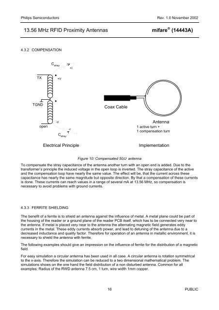
Philips Semiconductors Rev. 1.0 November 200213.56 MHz RFID Proximity Antennas mifare ® (14443A)4.3.2 COMPENSATIONC stray+ITX+VTGNDCoax Cableopen-VC stray-IAntenna1 active turn +1 <strong>com</strong>pensation turnElectrical PrincipleImplementationFigure 10: Compensated 50Ω antennaTo <strong>com</strong>pensate the stray capacitance of the antenna another turn with an open end is added. Due to thetransformer’s principle the induced voltage in the open loop is inverted. The stray capacitance of the activeand the <strong>com</strong>pensation loop have nearly the same value. The effect will be, that the current across thesecapacitance has nearly the same magnitude but opposite direction. By that a <strong>com</strong>pensation of these currentsis done. These currents can reach values in a range of several mA at 13.56 MHz, so <strong>com</strong>pensation isnecessary to avoid problems with ground currents.4.3.3 FERRITE SHIELDINGThe benefit of a ferrite is to shield an antenna against the influence of metal. A metal plane could be part ofthe housing of the reader or a ground plane of the reader PCB itself, which has to be connected very near tothe antenna. If metal is placed very near to the antenna the alternating magnetic field generates eddycurrents in the metal. These eddy currents absorb power, and lead to detuning of the antenna due to adecreased inductance and quality factor. Therefore for operation of an antenna in metallic environment, it isnecessary to shield the antenna with ferrite.The following examples should give an impression on the influence of ferrite for the distribution of a magneticfield.For easy simulation a circular antenna has been used in all case. A circular antenna is rotation symmetricalto the x-axis. Therefore the simulation can be reduced to a two dimensional mathematical problem. Thesimulations shows on the one hand the field distribution of a non disturbed antenna. Common for allexamples: Radius of the RWD antenna 7.5 cm, 1 turn, wire width 1mm copper.16 PUBLIC