Application Note 109 3-, 6-, and 12-Lead ECG - Biopac
Application Note 109 3-, 6-, and 12-Lead ECG - Biopac
Application Note 109 3-, 6-, and 12-Lead ECG - Biopac

You also want an ePaper? Increase the reach of your titles
YUMPU automatically turns print PDFs into web optimized ePapers that Google loves.
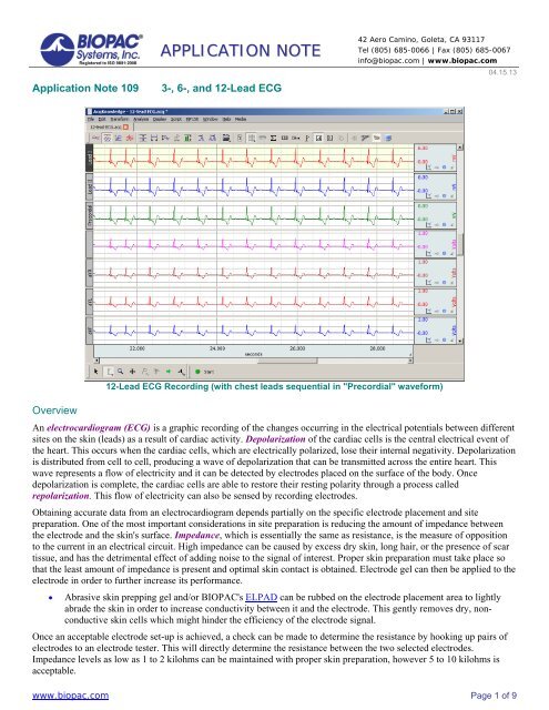
<strong>Application</strong> <strong>Note</strong> <strong>109</strong>APPLICATION NOTE3-, 6-, <strong>and</strong> <strong>12</strong>-<strong>Lead</strong> <strong>ECG</strong>42 Aero Camino, Goleta, CA 93117Tel (805) 685-0066 | Fax (805) 685-0067info@biopac.com | www.biopac.com04.15.13<strong>12</strong>-<strong>Lead</strong> <strong>ECG</strong> Recording (with chest leads sequential in "Precordial" waveform)OverviewAn electrocardiogram (<strong>ECG</strong>) is a graphic recording of the changes occurring in the electrical potentials between differentsites on the skin (leads) as a result of cardiac activity. Depolarization of the cardiac cells is the central electrical event ofthe heart. This occurs when the cardiac cells, which are electrically polarized, lose their internal negativity. Depolarizationis distributed from cell to cell, producing a wave of depolarization that can be transmitted across the entire heart. Thiswave represents a flow of electricity <strong>and</strong> it can be detected by electrodes placed on the surface of the body. Oncedepolarization is complete, the cardiac cells are able to restore their resting polarity through a process calledrepolarization. This flow of electricity can also be sensed by recording electrodes.Obtaining accurate data from an electrocardiogram depends partially on the specific electrode placement <strong>and</strong> sitepreparation. One of the most important considerations in site preparation is reducing the amount of impedance betweenthe electrode <strong>and</strong> the skin's surface. Impedance, which is essentially the same as resistance, is the measure of oppositionto the current in an electrical circuit. High impedance can be caused by excess dry skin, long hair, or the presence of scartissue, <strong>and</strong> has the detrimental effect of adding noise to the signal of interest. Proper skin preparation must take place sothat the least amount of impedance is present <strong>and</strong> optimal skin contact is obtained. Electrode gel can then be applied to theelectrode in order to further increase its performance.Abrasive skin prepping gel <strong>and</strong>/or BIOPAC's ELPAD can be rubbed on the electrode placement area to lightlyabrade the skin in order to increase conductivity between it <strong>and</strong> the electrode. This gently removes dry, nonconductiveskin cells which might hinder the efficiency of the electrode signal.Once an acceptable electrode set-up is achieved, a check can be made to determine the resistance by hooking up pairs ofelectrodes to an electrode tester. This will directly determine the resistance between the two selected electrodes.Impedance levels as low as 1 to 2 kilohms can be maintained with proper skin preparation, however 5 to 10 kilohms isacceptable.www.biopac.com Page 1 of 9
3-, 6-, <strong>and</strong> <strong>12</strong>-<strong>Lead</strong> <strong>ECG</strong> BIOPAC Systems, Inc.EQUIPMENT MP150 data acquisition system Three (3) <strong>ECG</strong>100C amplifier modules One (1) TSD155C Multi-lead <strong>ECG</strong> Cable Ten (10) EL503 electrodes per subject GEL100 Electrode GelHARDWARE SETUP1. Snap the three <strong>ECG</strong>100C modules to the UIM100C.2. Set the first (closest to the UIM100C) <strong>ECG</strong>100C amplifier to channel 1 on top.3. Set the second <strong>ECG</strong>100C amplifier to channel 2 on top4. Set the third <strong>ECG</strong>100C amplifier to channel 3 on top.5. Set the remaining switches on all three <strong>ECG</strong>100C amplifiers as follows:Gain: 2000 Mode: Norm35 Hz LPN: ON HP: 0.5 Hz (recommended for stable baseline; 0.05 Hz acceptable)6. Plug the TSD155C into the front panels of the <strong>ECG</strong>100C as follows.<strong>Lead</strong> I - first module (closest to UIM100C)<strong>Lead</strong> II - second moduleChest - third module7. Power on the MP150 unit..ELECTRODE CONNECTIONS1. Attach the electrodes as shown below.a. Abrade each electrode site. It is a good idea to abrade the skin before electrode placement to decrease theamount of impedance between the electrode <strong>and</strong> the skin's surface.b. Apply a small amount of electrode gel (GEL100) to each electrode. A drop of electrode gel will furtherimprove electrode detection.c. Apply 10 electrodes to the Subject.www.biopac.com Page 3 of 9
3-, 6-, <strong>and</strong> <strong>12</strong>-<strong>Lead</strong> <strong>ECG</strong> BIOPAC Systems, Inc.Electrode placement for<strong>Lead</strong>s I <strong>and</strong> IILeft Leg (LL) = RED leadLeft Arm (LA) = BLACK leadChest (C) = BROWN leadRight Arm (RA) = WHITE leadRight Leg (LL) = GREEN leadElectrode placement for precordial leads (for <strong>12</strong>-lead <strong>ECG</strong> option)V1 4 th intercostal space, right of sternumV2 4 th intercostal space, left of sternumV3 midway between V2 <strong>and</strong> V4V4 5 th intercostal space, in the midclavicular lineV5 same level as V4, at anterior axillary line (between V4<strong>and</strong> V6)V6 in 5 th intercostal space, in the midaxillary line2. Attach the electrode lead set (TSD155C) to the electrodes, paying close attention to the lead colors <strong>and</strong> startingwith the precordial (chest) lead connected at V1.ooRed LL left legBlack LA left armBrown C precordialWhite RA right armGreen RL right leg (ground)Position the electrode cables so they do not pull on the electrodes.Clip the electrode cable clip (where the cable meets the three individual colored wires) to a convenientlocation (such as Subject’s clothes) to relieve cable strain.www.biopac.com Page 4 of 9
3-, 6-, <strong>and</strong> <strong>12</strong>-<strong>Lead</strong> <strong>ECG</strong> BIOPAC Systems, Inc.SOFTWARE MODULE SETUP1. Select MP150 > Set Up Channels:a. Click choose <strong>ECG</strong>100C from the module list <strong>and</strong> click “Add.”b. Select “1” in the Choose Channel Switch Position dialog <strong>and</strong> click OK.c. In the <strong>ECG</strong>100C Configuration dialog (shown on right) click OK toaccept the default software settings.NOTE: The software settings must match the physical <strong>ECG</strong>100C amplifier settings described on page 3.d. In Input channels setup. Enter “<strong>Lead</strong> I” as the Label for Channel 1. (See figure below)Analog channel setup for 3-<strong>Lead</strong> <strong>ECG</strong> derived from 2 analog inputs (1 <strong>and</strong> 2)e. Repeat steps a-d above, choosing Channel 2 in step b by clicking the white channel selection box <strong>and</strong>sliding it to “2.” Following Step c, enter “<strong>Lead</strong> II” as the Label for Channel 2.f. Repeat steps a-d above, choosing Channel 3 in step b by clicking the white channel selection box <strong>and</strong>sliding it to “3.” Following step c, enter “Chest” as the Label for Channel 3.IMPORTANT: Make certain the channel switch position on top of the <strong>ECG</strong>100C amplifier matches the channel switchposition selected in the software.www.biopac.com Page 5 of 9
3-, 6-, <strong>and</strong> <strong>12</strong>-<strong>Lead</strong> <strong>ECG</strong> BIOPAC Systems, Inc.2. Click the Calculation tab <strong>and</strong> set calculation channel C0 to acquire <strong>and</strong> plot data. Select Math from the Presetmenu <strong>and</strong> label it "<strong>Lead</strong> III.”3. Click “Setup…” button <strong>and</strong> set the Source <strong>and</strong> Operation options for "A2 (<strong>Lead</strong> II) - A1 (<strong>Lead</strong> I)." Click OK(see figure below).<strong>Lead</strong> III set-up as a Math : Calculation channel (C0) derived from thedifference between <strong>Lead</strong>s I <strong>and</strong> II (A1 <strong>and</strong> A2, respectively)4. Under MP150 > Set Up Acquisition, choose "Record <strong>and</strong> Append using Memory" <strong>and</strong> set the sampling rate to250 Hz with an acquisition length of 10 seconds. <strong>Note</strong>: To record data for HRV analysis, set sampling rate to1000 Hz.oIn Append mode, when the acquisition is stopped <strong>and</strong> then re-started, data will be added onto the previousdata. An append marker will automatically be inserted with a time stamp to indicate the new segment starttime. You can re-label the marker at any time.PROCEDURE1. After completing the above steps for AcqKnowledge software setup, click on the software’s "Start" button.o Waveforms may take several seconds to settle properly.2. Wait for the acquisition to stop (set for 10 seconds) or click on the "Stop" button in the software when you haveacquired the desired amount of data.3. Modify the vertical scale to the desired values <strong>and</strong> perform the "Autoscale waveforms" function from the Displaymenu.4. To record heart rate, select Analysis > Find Rate from the pull-down menus. This will create a new channelwhich records the BPM of the selected waveform (see figure below).Sample waveform with Analysis > Find Rate BPM channelwww.biopac.com Page 6 of 9
3-, 6-, <strong>and</strong> <strong>12</strong>-<strong>Lead</strong> <strong>ECG</strong> BIOPAC Systems, Inc.Option # 1: 6-<strong>Lead</strong> <strong>ECG</strong>In order to acquire 6-lead <strong>ECG</strong> information, you will need to calculate the three augmented leads, also termed theGoldberger leads. These leads are derived from advanced vector-cardiography based on the three st<strong>and</strong>ard leads (<strong>Lead</strong>s I,II, <strong>and</strong> III). No additional electrodes or leads are required to obtain the augmented leads as they are functions of the threest<strong>and</strong>ard leads <strong>and</strong> can be calculated online or post-acquisition with the following formulas:aVR = - (<strong>Lead</strong> I + <strong>Lead</strong> II) / 2aVL = (<strong>Lead</strong> I - <strong>Lead</strong> III) / 2aVF = (<strong>Lead</strong> II + <strong>Lead</strong> III) / 2where <strong>Lead</strong> I correlates to software channel A1, <strong>Lead</strong> II correlate to software channels A2, <strong>and</strong> <strong>Lead</strong> III correlates tosoftware channel C01. Click on MP > Setup Channels <strong>and</strong> set three additional Calculation channels to acquire, plot <strong>and</strong> show values.2. Set each new calculation channel to the Expression preset (click “Setup…” button) <strong>and</strong> enter the formulas foraVR, aVL, or aVF in each Expression setup dialog.3. Click OK to close out of the dialog <strong>and</strong> proceed with the recording.Option # 2: <strong>12</strong>-<strong>Lead</strong> <strong>ECG</strong>In some remote cases 6-lead <strong>ECG</strong> does not give enough information about the electrical activity of the heart. It is possibleto add six more leads for a total of <strong>12</strong> leads, hence the title <strong>12</strong>-<strong>Lead</strong> <strong>ECG</strong>. The six new leads, called precordial leads, orchest leads, are arranged across the chest in a horizontal plane <strong>and</strong> record electrical flows moving anteriorly <strong>and</strong>posteriorly.To create the six precordial leads, each chest electrode is positive, <strong>and</strong> the whole body is used as the common ground. Thesix positive electrodes, creating the precordial leads V1 through V6 are positioned as shown in the diagram above <strong>and</strong>rotated through consecutive recording segments to provide <strong>12</strong>-lead <strong>ECG</strong> data. For continuous <strong>12</strong>-lead <strong>ECG</strong>, see <strong>Application</strong> <strong>Note</strong> #AH-206<strong>Note</strong>The optimum setup is Subject relaxed <strong>and</strong> in a supine position.You will record six 10-second segments, for a total recording of 60 seconds. You willrecord <strong>Lead</strong> I, <strong>Lead</strong> II <strong>and</strong> a Precordial (chest) lead in six positions (V1 through V6). Inaddition, <strong>Lead</strong> III <strong>and</strong> the "Augmented leads" (aVr, aVl, aVf) will be calculated. Eachchest electrode is positive <strong>and</strong> the whole body is used as the common ground.Wait at least 30 seconds after moving the precordial lead for each segment beforeclicking on "Start."A marker will be inserted each time you click "Start" <strong>and</strong> you can label markers afterrecording.You should not see excessive EMG artifact or baseline drift; if you do, checkconnections <strong>and</strong> repeat the segment.1. Segment 1: Precordial V1a. Confirm that the chest lead is still securely clipped to Subject at position V1.b. Click on the Start button.• Subject must maintain the same position for all segments.c. After 10 seconds, click on the Stop button.d. Review the data on the screen.• You should not see excessive EMG artifact or baseline drift; if you do, check connections <strong>and</strong>repeat the segment.www.biopac.com Page 7 of 9
3-, 6-, <strong>and</strong> <strong>12</strong>-<strong>Lead</strong> <strong>ECG</strong> BIOPAC Systems, Inc.2. Segment 2: Precordial V2a. Unclip the chest lead from position V1 <strong>and</strong> clip it to position V2.b. Wait 30 seconds <strong>and</strong> then click on Start.• Subject must maintain the same position for all segments.c. After 10 seconds, click on Stop.3. Segment 3: Precordial V3a. Unclip the chest lead from position V2 <strong>and</strong> clip it to position V3.b. Wait 30 seconds <strong>and</strong> then click on Start.• Subject must maintain the same position for all segments.c. After 10 seconds, click on Stop.4. Segment 4: Precordial V4a. Unclip the chest lead from position V3 <strong>and</strong> clip it to position V4.b. Wait 30 seconds <strong>and</strong> then click on Start.• Subject must maintain the same position for all segments.c. After 10 seconds, click on Stop.5. Segment 5: Precordial V5a. Unclip the chest lead from position V4 <strong>and</strong> clip it to position V5.b. Wait 30 seconds <strong>and</strong> then click on Start.• Subject must maintain the same position for all segments.c. After 10 seconds, click on Stop.6. Segment 6: Precordial V6a. Unclip the chest lead from position V5 <strong>and</strong> clip it to position V6.b. Wait 30 seconds <strong>and</strong> then click on Start.• Subject must maintain the same position for all segments.c. After 10 seconds, click on Stop.7. Remove the leads <strong>and</strong> electrodes from the Subject.8. Label the markers V1-V6 if you did not do so at the start of each segment.• <strong>Note</strong> that the markers apply only to the "Precordial" channel, <strong>and</strong> represent the rotation of the precordiallead from position V1 through V6.www.biopac.com Page 8 of 9
3-, 6-, <strong>and</strong> <strong>12</strong>-<strong>Lead</strong> <strong>ECG</strong> BIOPAC Systems, Inc.ANALYSISThe <strong>12</strong>-lead <strong>ECG</strong> data will be displayed as follows:ChannelCH 1CH 2CH 3C 1 (40)C 2 (41)C 3 (42)C 4 (43)Displays<strong>Lead</strong> I<strong>Lead</strong> IIV1 – V6 (per markers)<strong>Lead</strong> III (calculated)aVR (calculated)aVL (calculated)aVF (calculated)To hide channels in the display, Alt-click the channel box. The channel box will be crossed over <strong>and</strong> the channel will bedropped from the data display. No data is removed from the data file — this function affects data display only. To show ahidden channel, Alt-click the channel box again.AcqKnowledge software offers a wide array of measurement <strong>and</strong> analysis tools to help you isolate the data segments ofinterest for your particular experiment. See the AcqKnowledge Software Guide for details.Return To <strong>Application</strong> <strong>Note</strong> Menuwww.biopac.comPage 9 of 9