
You also want an ePaper? Increase the reach of your titles
YUMPU automatically turns print PDFs into web optimized ePapers that Google loves.
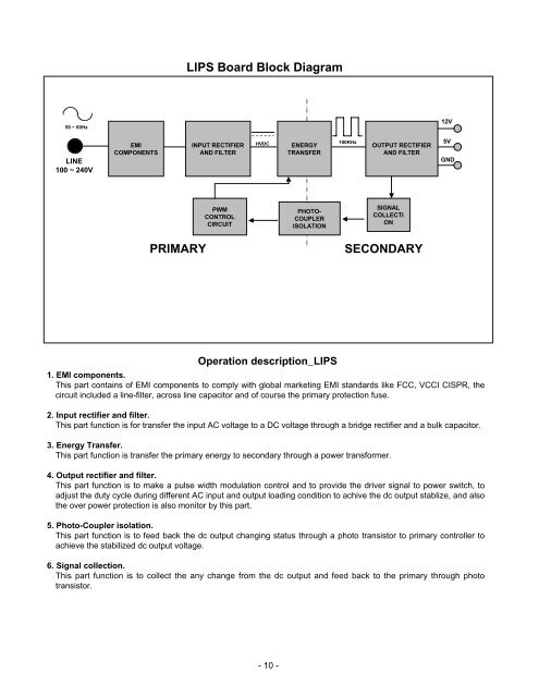
LIPS Board Block Diagram50 ~ 60Hz12VLINE100 ~ 240VEMICOMPONENTSINPUT RECTIFIERAND FILTERHVDCENERGYTRANSFER100KHzOUTPUT RECTIFIERAND FILTER5VGNDPWMCONTROLCIRCUITPHOTO-COUPLERISOLATIONSIGNALCOLLECTIONPRIMARYSECONDARYOperation description_LIPS1. EMI components.This part contains of EMI components to comply with global marketing EMI standards like FCC, VCCI CISPR, thecircuit included a line-filter, across line capacitor and of course the primary protection fuse.2. Input rectifier and filter.This part function is for transfer the input AC voltage to a DC voltage through a bridge rectifier and a bulk capacitor.3. Energy Transfer.This part function is transfer the primary energy to secondary through a power transformer.4. Output rectifier and filter.This part function is to make a pulse width modulation control and to provide the driver signal to power switch, toadjust the duty cycle during different AC input and output loading condition to achive the dc output stablize, and alsothe over power protection is also monitor by this part.5. Photo-Coupler isolation.This part function is to feed back the dc output changing status through a photo transistor to primary controller toachieve the stabilized dc output voltage.6. Signal collection.This part function is to collect the any change from the dc output and feed back to the primary through phototransistor.- 10 -