Granular jamming with hydraulc control - King's College London
Granular jamming with hydraulc control - King's College London
Granular jamming with hydraulc control - King's College London
You also want an ePaper? Increase the reach of your titles
YUMPU automatically turns print PDFs into web optimized ePapers that Google loves.
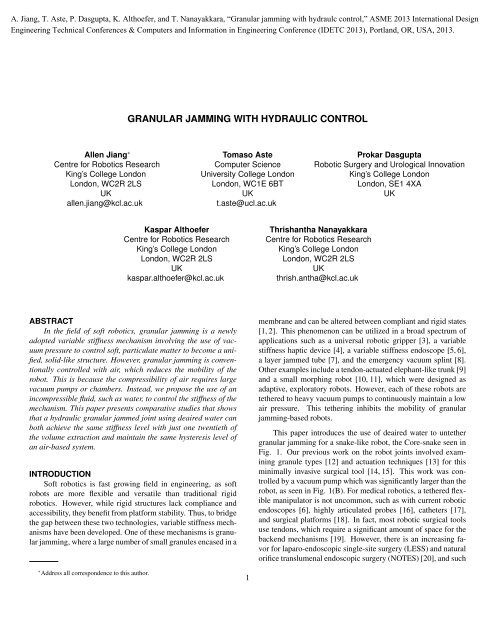
Finally, the conversion from shear stresses in Eqn. 2 to theexternal bending force F ext is as follows:F ext = τA (6)where A is the cross-sectional area of the joint.The values used to calculate the load force at the joint tip isoutlined in table 1. For the pneumatic system, the internal jointpressure level is set to 18 kPa (2.6 PSI-A) to reflect the pressureused in the experiments. Thus, σ was set to 83 kPa (12 PSI-A),resulting in a loading force of 0.43 N. For the hydraulic system,σ is estimated to occur at full water evacuation, and thusly set to101 kPa (14.6 PSI-A). This results in a force of 0.53 N, higherthan its pneumatic counterpart.FIGURE 2: Experimental setup for the hydraulic test. For thepneumatic experiments, a pressure sensor was attached to theport hole.METHODSHemispherical acrylic granules 1 mm in diameter were usedas the granular media. The variable stiffness joint membrane isa 0.2 mm thick latex cylinder 10 mm diameter by 30 mm longcylinder (2.36 mL volume). Because the Core-snake must largelyresist lateral disturbances, its perpendicular stiffness is most critical.As such, bending tests were performed. These tests consistof measuring the resulting force when deflecting the joint tip perpendicularlyto its axis by 10 mm. An ATI Nano17 Force/TorqueTABLE 1: Simulation ResultsHydraulicPneumaticF ext (N) 0.53 0.43τ (kPa) 6.73 5.53σ (kPa) 101 83A (mm 2 ) 78.5 78.5η H (kPa-s) 1 1˙γ (mm/s) 1 1µ k 0.2 0.2µ s 0.2 0.2P s (kPa) 33.7 27.7d (mm) 1ρ p (kg/m 3 ) 1180sensor measured the resultant force, and a Maxon EC-30 motorpowered linear module <strong>control</strong>led the deflection distance.The first experiment consisted of an air <strong>control</strong> test. Thisbaseline, <strong>control</strong> test was performed <strong>with</strong> an internal air pressureof 101 kPa (14.6 PSI absolute), which matches the external atmosphericpressure. The <strong>control</strong> test measures the lower boundof the joint’s stiffness, or its “soft” state. The upper bound of thepneumatic experiment consisted of continuously vacuuming thejoint to an internal air pressure of 18 kPa (2.6 PSI absolute). Thiswas achieved <strong>with</strong> a Mastercool 90066-2V-220 Vacuum Pumpattached to an intermediate 5.3 liter vacuum chamber. The internaljoint pressure was measured in-line by a Honeywell 0-30PSI Absolute pressure sensor. To compare the effectiveness of apneumatic system in an untethered environment, an air syringetest was performed. Here, 10 mL of air was evacuated via a syringe,and the resulting force was measured.The second experiment consisted of a water <strong>control</strong> test.This test is similar to the air <strong>control</strong> test, <strong>with</strong> the exception thatthe spaces between granules are filled <strong>with</strong> water, rather than air.The upper bound of the hydraulic experiment consisted of a 10mL syringe installed in place of the vacuum pump and evacuatingthe water <strong>with</strong>in the joint. 0.5 mL was water was evacuated toachieve a stiffened joint. The water used is known as deaired water,where water subjugated to a process of removing dissolvedair inside the liquid. Water was placed <strong>with</strong>in a vacuum chamberand vibrated, as the chamber pressure was decreased. This processwas done to ensure a uniform and consistent water density.While other hydraulic systems may use oil as the base stock, theuse of oil is outside the scope of this paper.This study examines the stiffness range and hysteresis of thesystems. The stiffness range is the maximum stiffness K max mi-3
FIGURE 3: Air <strong>control</strong> experiment where the variable stiffnessjoint is deflected 10 mm, under atmospheric pressure.FIGURE 4: Experimental result <strong>with</strong> a continuous vacuum draw,<strong>with</strong> internal pressure set to 18 kPa (2.6 PSI-A).nus the <strong>control</strong> stiffness, which is also the minimum stiffnessK <strong>control</strong> . The hysteresis value H for each experiment is normalizedand is calculated by the difference in area of the pushingand returning curves divided by the area of the pushing curve(H = A push−A returnA push).EXPERIMENTAL RESULTSSeveral experiments were performed to validate the simulationresults in Tab. 1, and to compare a hydraulic granular <strong>jamming</strong>system to a traditional pneumatic system. Between 5-10trials were performed for each experiment.Pneumatic ControlTo have a comparative base for the hydraulic <strong>control</strong> tests, aset of identical pneumatic <strong>control</strong> experiments were performed.One, the joint is in a compliant state; and two, the joint is in arigid state.Figure 3 shows the results of the pneumatic joint “softness”test, where the variable stiffness joint is deflected <strong>with</strong>out a pressuredifferential to the environment. Here, the granules are ina minimal state of static equilibrium, in which they are settled,but are easily perturbed. This is taken to be the φ RLP factor forthe pneumatic joint. There is a very low amount of hysteresis at11%, and low stiffness as well. The peak force measured was0.08 N. There is a fairly linear behavior to the curves.With a continuous vacuum draw of 18 kPa, the variable stiffnessjoint is able to achieve 0.32 N at the 10 mm deflection mark,as shown in Fig. 4.As shown in Fig. 5, a comparative experiment was performedto highlight the difference between a continuous vacuumFIGURE 5: Experimental result <strong>with</strong> 10 mL of air evacuated viaa syringe.draw system and a hydraulic system. The vacuum pump was replaced<strong>with</strong> an air-filled syringe, and 10 mL of air was evacuated.This system achieved a peak force of 0.21 N.Unlike the <strong>control</strong> test in Fig. 3, there is a visible cutoff pointin the return phases for both the continuous vacuum draw test andair syringe test. In Fig. 4, the measurable force reaches 0 N atthe 5 mm point, and in 5, it also occurs at the 5 mm point. At thispoint, the joint is no longer in contact <strong>with</strong> the force sensor, asthe joint has permanently deformed to this state. Experimentally,the joint was reset before the subsequent trial.Also unlike the <strong>control</strong> test, the pneumatic systems, while4
draw system. The stiffness characteristics of a water-filled jointin a unstiffened state were the same as an air-filled joint, as seenin Fig. 3.However, while the use of water has many advantages overair, for a granular <strong>jamming</strong> system, there are also several disadvantagesobserved from our experiments. In a pneumatic system,particularly one involving a continuously running vacuum pump,leaks <strong>with</strong>in the system would decrease the stiffness performanceof granular <strong>jamming</strong>, but not render it unusable. For a hydraulicsystem, however, the fixed-volume syringe could not overcomeleakages. When the hydraulic system began filling <strong>with</strong> air dueto a leak, the variable stiffness joint could no longer stiffen, evenif the syringe was drawn the full 10 mL. Reversing the syringetended to expand the membrane, rather than release the air, aswell. Another disadvantage of a hydraulic system is that theweight of water may be too much for the system. Though thehydraulic system can achieve the same stiffness as a pneumaticone, the mass of the water collected in a chamber at each jointwould add weight to a multi-jointed snake. However, joint designor compensation related to the added weight is outside thescope of this paper.It should be noted that the hydraulic system could theoreticallyachieve a higher stiffness if the syringe in the experimentalsetup were more robust. Though the hydraulic pressure wasnot measured, the author estimates that full evacuation was notachieved in the joint. The brackets supporting the syringe wereflexing during the experiment, which could have skewed the experimentalresults. The linear module and motor, however, wereable to actuate and maintain a stable position.To test the feasibility of transforming granular <strong>jamming</strong> intoan untethered system, a 3 volt, battery powered DC motor wasattached to the linear module <strong>control</strong>ling the syringe (Fig. 2).The motor was able to successfully jam the joint by evacuating0.5 mL of water and holding its position on the linear module.CONCLUSIONS AND FUTURE WORKSIn this paper we demonstrate a novel means of regulatingthe stiffness of a granular <strong>jamming</strong> joint by the use of deairedwater. The results show that a hydraulic granular <strong>jamming</strong> systemrequires 20 times less volume than a pneumatic system toachieve the same stiffness. Additionally, a hydraulic system isable to achieve a 50% lower minimum stiffness than a pneumaticone. This opens a new field in granular <strong>jamming</strong> research forrobotics, as a hydraulic granular <strong>jamming</strong> system can be used formobile and field robotics, as well as in the medical field.Future works include studying the granular interactions <strong>with</strong>water or other hydraulic base stocks. Certain granules may besusceptible to cohesion or other interparticle forces when introducedto a fluid. Such phenomenon can be exploited to achievebetter stiffnesses and hysteresis in future compliant joints. Furthermore,additional investigations on intermediate stiffness levelsshould be conducted for hydraulic systems. In pneumatic systems,an intermediate vacuum pressure level results in a semistiffand a semi-soft state. However, in hydraulic systems, thelinear module regulating the syringe should have an impedance<strong>control</strong>ler to dynamically alter the desired stiffness of the joint.Improving the current numerical model and simulation methodswill also be studied. Lastly, further research will be done onminiaturizing the hydraulic granular <strong>jamming</strong> joint system andcreating an independent, <strong>control</strong>lable module.ACKNOWLEDGMENTThis work was partly funded by the Guy’s and St Thomas’Hospital Trust Foundation, the Engineering and Physical SciencesResearch Council (EPSRC), UK, under grant agreementEP/I028773/1, and by the Seventh Framework Programme ofthe European Commission under grant agreement 287728 in theframework of EU project STIFF-FLOP.REFERENCES[1] Aste, T., and Weaire, D., 2008. The pursuit of perfect packing.Taylor & Francis.[2] Liu, A. J., and Nagel, S. R., 1998. “Nonlinear dynamics:Jamming is not just cool any more”. Nature, 296, pp. 21–22.[3] Brown, E., Rodenberg, N., Amend, J., Mozeika, A., Steltz,E., Zakin, M. R., Lipson, H., and Jaeger, H. M., 2010. “Universalrobotic gripper based on the <strong>jamming</strong> of granular material”.Proceedings of the National Academy of Sciences ofthe United States of America, 107(44), pp. 18809–18814.[4] Mitsuda, T., Kuge, S., Wakabayashi, M., and Kawamura,S., 2002. “Wearable haptic display by the use of a particlemechanical constraint”. Proceedings. 10th Symposium onHAPTICS 2002, pp. 153–158.[5] Loeve, A. J., van de Ven, O. S., Vogel, J. G., Breedveld,P., and Dankelman, J., 2010. “Vacuum packed particles asflexible edoscope guides <strong>with</strong> <strong>control</strong>lable rigidity”. <strong>Granular</strong>Matter, 12, pp. 543–554.[6] Loeve, A., Breedveld, P., and Dankelman, J., 2010. “Scopestoo flexible...and too stiff”. Pulse, IEEE, 1(3), nov.-dec.,pp. 26 –41.[7] Kim, Y.-J., Cheng, S., Kim, S., and Iagnemma, K., 2012.“Design of a tubular snake-like manipulator <strong>with</strong> stiffeningcapability by layer <strong>jamming</strong>”. In Intelligent Robots andSystems (IROS), 2012 IEEE/RSJ International Conferenceon, pp. 4251 –4256.[8] Letts, R., and Hobson, D., 1973. “The vacuum splint: anaid in emergency splinting of fractures”. Canadian MedicalAssociation Journal, 109(7), p. 599.[9] Cheng, N. G., Lobovsky, M. B., Keating, S. J., Setapen,A. M., Gero, K. I., Hosoi, A. E., and Iagnemma, K. D.,6
2012. “Design and analysis of a robust, low-cost, highly articulatedmanipulator enabled by <strong>jamming</strong> of granular media”.2012 IEEE ICRA, May, pp. 4328 –4333.[10] Steltz, E., Mozeika, A., Rodenberg, N., Brown, E., andJaeger, H., 2009. “Jsel: Jamming skin enabled locomotion”.In Intelligent Robots and Systems, 2009. IROS 2009.IEEE/RSJ International Conference on, pp. 5672 –5677.[11] Steltz, E., Mozeika, A., Rembisz, J., Corson, N., andJaeger, H., 2010. “Jamming as an enabling technology forsoft robotics”. In Society of Photo-Optical InstrumentationEngineers (SPIE) Conference Series, Vol. 7642, p. 63.[12] Jiang, A., Ataollahi, A., Althoefer, K., Dasgupta, P., andNanayakkara, T., 2012. “A variable stiffness joint bygranular <strong>jamming</strong>”. In Proceedings of the ASME 2012International Design Engineering Technical Conferences& Computers and Information in Engineering ConferenceIDETC/CIE 2012.[13] Jiang, A., Xynogalas, G., Dasgupta, P., Althoefer, K., andNanayakkara, T., 2012. “Design of a variable stiffnessflexible manipulator <strong>with</strong> composite granular <strong>jamming</strong> andmembrane coupling”. In 2012 IEEE/RSJ IROS, pp. 2922–2927.[14] Jiang, A., Althoefer, K., Nanayakkara, T., and Dasgupta,P., 2012. “<strong>Granular</strong> <strong>jamming</strong> for minimally invasive surgeries”.In 30th World Congress of Endourology and SWL(WCE 2012).[15] Wurdemann, H., Jiang, A., Nanayakkara, T., Seneviratne,L., and Althoefer, K., 2012. “Variable stiffness <strong>control</strong>lableand learnable manipulator for mis”. In IEEE InternationalConference on Robotics and Automation (ICRA2012) Workshop.[16] Degani, A., Choset, H., Zubiate, B., Ota, T., and Zenati, M.,2008. “Highly articulated robotic probe for minimally invasivesurgery”. 2008 30th Annual International Conferenceof the IEEE Engineering in Medicine and Biology Society,Vols 1-8, pp. 3273–3276.[17] Webster, R. J., Romano, J. M., and Cowan, N. J., 2009.“Mechanics of precurved-tube continuum robots”. IeeeTransactions on Robotics, 25(1), pp. 67–78.[18] Noonan, D. P., Vitiello, V., Shang, J., Payne, C. J., andYang, G.-Z., 2011. “A modular, mechatronic joint designfor a flexible access platform for mis”. In Intelligent Robotsand Systems (IROS), 2011 IEEE/RSJ International Conferenceon, pp. 949 –954.[19] Kuo, C., Taylor, R., Dai, J., and Iordachita, I., 2010. “Designof a flexural transmission for a dexterous telesurgicalrobot for throat and upper airway: a preliminary result”.In Proc. of the Hamlyn Symposium on Medical Robotics,pp. 71–72.[20] Auyang, E., Santos, B., Enter, D., Hungness, E., and Soper,N., 2011. “Natural orifice translumenal endoscopic surgery(notes): a technical review”. Surgical Endoscopy, 25,pp. 3135–3148. 10.1007/s00464-011-1718-x.[21] Vyas, L., Aquino, D., Kuo, C. H., Dai, J. S., and Dasgupta,P., 2011. “Flexible robotics”. Bju International, 107(2),pp. 187–189.[22] Jerkins, M., Schröter, M., Swinney, H., Senden, T., Saadatfar,M., and Aste, T., 2008. “Onset of mechanical stabilityin random packings of frictional spheres”. Physical reviewletters, 101(1), p. 18301.[23] Goren, L., Aharonov, E., Sparks, D., and Toussaint, R.,2011. “The mechanical coupling of fluid-filled granularmaterial under shear”. Pure and Applied Geophysics,168(12), pp. 2289–2323.[24] Mills, P., and Snabre, P., 2009. “Apparent viscosity and particlepressure of a concentrated suspension of non-brownianhard spheres near the <strong>jamming</strong> transition”. The EuropeanPhysical Journal E, 30, pp. 309–316.[25] Pouliquen, O., Cassar, C., Jop, P., Forterre, Y., and Nicolas,M., 2006. “Flow of dense granular material: towardssimple constitutive laws”. Journal of Statistical Mechanics:Theory and Experiment, 2006(07), p. P07020.[26] Yurkovetsky, Y., and Morris, J., 2008. “Particle pressurein sheared brownian suspensions”. Journal of rheology,52(1), pp. 141–164.7


