411 - Creating Exploded and Animated Assemblies - Solid Edge ...
411 - Creating Exploded and Animated Assemblies - Solid Edge ...
411 - Creating Exploded and Animated Assemblies - Solid Edge ...
You also want an ePaper? Increase the reach of your titles
YUMPU automatically turns print PDFs into web optimized ePapers that Google loves.
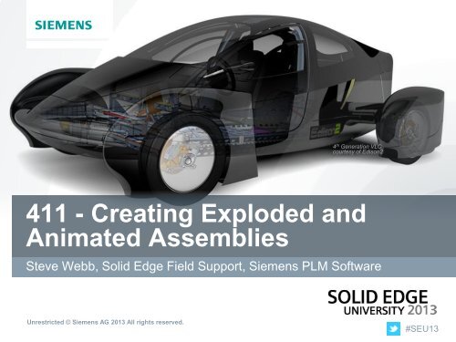
4 th Generation VLCcourtesy of Edison2<strong>411</strong> - <strong>Creating</strong> <strong>Exploded</strong> <strong>and</strong><strong>Animated</strong> <strong>Assemblies</strong>Steve Webb, <strong>Solid</strong> <strong>Edge</strong> Field Support, Siemens PLM SoftwareUnrestricted © Siemens AG 2013 All rights reserved.#SEU13
Agenda: <strong>411</strong> - <strong>Creating</strong> <strong>Exploded</strong> <strong>and</strong> <strong>Animated</strong><strong>Assemblies</strong>Who am I?What you will learnDemonstrations4 th Generation VLCcourtesy of Edison2Unrestricted © Siemens AG 2013 All rights reserved.Page 2Siemens PLM Software
About: Steve WebbSteve Webb<strong>Solid</strong> <strong>Edge</strong> Field SupportSiemens PLM SoftwareSteve is an Applications Engineer in the <strong>Solid</strong> <strong>Edge</strong> Field Support group. He hasover 25 years of experience in Mechanical Design Engineering <strong>and</strong> MechanicalCAD. He has held roles as an Application Engineer <strong>and</strong> Educator at SiemensPLM Software, PTC, Saratech Inc <strong>and</strong> Moderntech SI. Before moving into theCAD Industry, Steve applied his CAD knowledge in industries including hydraulicgear pumps, high speed packaging equipment, <strong>and</strong> textile equipment. He holdsa two year drafting certification from the Williamston Career <strong>and</strong> TechnologyCenter.Unrestricted © Siemens AG 2013 All rights reserved.Page 3Siemens PLM Software
What you will learnIn this session we will take a deep drive into the two different ways a user cancreate an exploded assembly <strong>and</strong> which method is the correct way for the outputthat is needed. The <strong>Solid</strong> <strong>Edge</strong> Explode Rendering Animate (ERA) environmenthas many tools to allow you to create the perfect explosion of your designs, <strong>and</strong>all of these tools will be covered. Once the exploded model has been created,we’ll then cover how to animate it. If you need to create exploded drawings, orshow how your designs are assembled or dissembled, this is a must attendsession.Unrestricted © Siemens AG 2013 All rights reserved.Page 4Siemens PLM Software
ExplodeDid you know - That in <strong>Solid</strong> <strong>Edge</strong> there’s two differentways to use exploded assemblies? Not just meaning Explode <strong>and</strong>Auto-Explode.• Animations• Saving video of assembly components moving in 3D.• Drawings• Make detailed 2D ISO drawing views for draft files.Unrestricted © Siemens AG 2013 All rights reserved.Page 5Siemens PLM Software
Animations – Auto Explode vs. ExplodeAuto Explode• Auto Explode uses these assembly relationships to explodeassemblies <strong>and</strong> subassemblies.• Mate• Axial Align• Any parts that have a Ground relation can not be Auto <strong>Exploded</strong>.• If working with In Context built parts, Auto Explode will notexplode those parts because they are grounded when located.Unrestricted © Siemens AG 2013 All rights reserved.Page 6Siemens PLM Software
Animations – Auto Explode vs. Explode• Auto Explode has a option to Bind all Subassemblies meaning ifa subassembly is in a top-level assembly treat the sub as asingle unit.• Turning off the Binding option will explode the subassembly.Demo-1Unrestricted © Siemens AG 2013 All rights reserved.Page 7Siemens PLM Software
Animations – Explode PathFinder• Explode PathFinder allows the user to change the exploitationvalues for the entire Group or each Event in the assembly.• Can select Groups, Events, parts <strong>and</strong>subassemblies from the PathFinder tochange the explosion distance.• Can select from the graphics window tochange the explosion distance.Demo-2Unrestricted © Siemens AG 2013 All rights reserved.Page 8Siemens PLM Software
Animations – Auto Explode vs. ExplodeExplode• More control than Auto Explode.• Grounded parts can be exploded with the Explode comm<strong>and</strong>.• Explode in different direction from Mate <strong>and</strong> Axial Align whenother relationships are used.• Explode can be used to edit explosions created with the AutoExplode comm<strong>and</strong>.Demo-3Unrestricted © Siemens AG 2013 All rights reserved.Page 9Siemens PLM Software
Drawings – Auto Explode,Explode, Drag ComponentDrawing view explosions are used to create precision 2D drawingviews. When creating drawing view explosions of assemblies, usercan use the Explode or Auto-Explode to create a starting point forthe drawing view.Top finalize the explode the following tools can be used:• Drop – will remove all the events placed by the Explode or Auto-Explode comm<strong>and</strong>s.• Drag Component – create the precision moves to display thecorrect location of the parts.• Flow Lines – simulate the direction of the parts.Demo-4Unrestricted © Siemens AG 2013 All rights reserved.Page 10Siemens PLM Software
Explode – Flow Lines• This comm<strong>and</strong> allows the user to drawflow lines for Draft <strong>and</strong> Drawingdocumentation purposes.• These annotation flow lines are for display <strong>and</strong> drawing view useonly <strong>and</strong> are not in any way associated with explode events• The auto <strong>and</strong> manual explode comm<strong>and</strong>s create events usedin animationUnrestricted © Siemens AG 2013 All rights reserved.Page 11Siemens PLM Software
Explode – Flow Line Enhancements• These flow lines are driven by the location <strong>and</strong> connection points to thecomponents <strong>and</strong> update as the components are moved• The Flow Line comm<strong>and</strong>s are disabled until an explosion has occurred or acomponent is movedUnrestricted © Siemens AG 2013 All rights reserved.Page 12Siemens PLM Software
Explode – Flow Line Enhancements• The idea behind the flow line comm<strong>and</strong> is to provide an easy to use tool toassist the user in manually creating the flow lines they want for draft <strong>and</strong>drawing documentation purposes.• A typical workflow to using this tool is to first create an exploded view usingeither the auto or manual method or drag component.• When this is done, <strong>Solid</strong> <strong>Edge</strong> creates“Explosion Events” in Explode PathFinderDemo-5Unrestricted © Siemens AG 2013 All rights reserved.Page 13Siemens PLM Software
4 th Generation VLCcourtesy of Edison2Thank YouSteve Webb, <strong>Solid</strong> <strong>Edge</strong> Field Support, Siemens PLM SoftwareUnrestricted © Siemens AG 2013 All rights reserved.#SEU13


