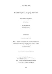
1.00.8Eθ/ E l(-)0.60.4G lt0.20.00 15 30 45 60 75 90θ (°)FIGURE 5 Normalized off-axis Young’s modulus, E θ /E l , calculated with E l = 130 GPa (that of atypical foil described in Chapter II), E t = 2 GPa, v lt = 0.4 and values of the shear modulus, G lt , of,resp. , 0.1, 1, and 10 GPa.To reduce the anisotropic properties of the foils, it is common practice to stackdifferently oriented foils, and bind them together to form a laminate. The stiffness ofsuch multi-foil laminates is described by classical lamination theory. Assuming thatthe in-plane strains in all foils are equal and that all foils have the same thickness, theelastic behavior of the laminate follows from the average value of the stiffness tensor,taking into account for each foil the mismatch between the loading and longitudinaldirection. Analogous to the case of a single foil, the Young’s modulus of the laminateas a function of loading angle then follows from the average compliance tensor, whichis the inverse of the average stiffness tensor, albeit not resulting in a simple relation asEquation 1. In general, not surprisingly, the anisotropy of the laminate is reduced withincreasing number of differently oriented foils and may even vanish. This is depictedin Figure 6, which shows the angular dependence of the Young’s modulus of a singlefoil, a [0/ 90], [0/ 60/ 120] and [0/ 45/ 90/ 135] laminate. In this figure, it can beobserved that the in-plane Young’s modulus for the latter two laminates is independentof the loading direction, and such laminates are, therefore, referred to as “quasiisotropic”.The general lay-up that leads to quasi-isotropic laminates is⎡ 180 180 ⎤⎢0/ / /( m − 1)⎣ mm ⎥⎦, where m is the number of different orientations in thelaminate, with m ≥ 3. For all these laminates the in-plane stiffness constants can be-20-
expressed as: 61 21 1 El( El + Et − 2 νltEt)G = Glt+2 8 E −νEl lt t(5)ν =1 1 El( El + Et + 6 νltEt)− Glt+22 8 El −νltEt1 1 E (3E + 3E + 2 ν E )Glt+2 8l l t lt t2El −νltEt(6)E = 2(1 + ν ) G(7)For most oriented polymer foils it holds that E l à E t , G lt . Under these conditions, theabove in-plane elastic constants approach asymptotically the following limitingvalues: 61 El1 ElE ≈ , ν ≈ , G ≈ (8)3 3 8AB1.00.8CDE θ / E l (-)0.60.4AC, D0.2B0.00 15 30 45 60 75 90θ (°)FIGURE 6 Various ply geometries of uniaxially oriented layers and their normalized off-axisYoung’s modulus, E θ /E l , calculated with E l = 130 GPa, E t = 2 GPa, G lt = 800 MPa and v lt = 0.4 (seetext): A Single, unidirectional layer [θ = 0], B Cross-ply [0/ 90], C [0/ 60/ 120], and D [0/ 45/ 90/ 135]laminate.-21-
- Page 3: Diss. ETH No. 17603Ultra-high-perfo
- Page 7: «I do not propose to say much abou
- Page 10 and 11: Ultra-high-performance unidirection
- Page 12 and 13: Hauptketten wirken bei den Aramidfa
- Page 14 and 15: Planare HochleistungsfolienWie bere
- Page 16 and 17: Feuilles de polymères hautes-perfo
- Page 19 and 20: 1 BackgroundThe use of polymers in
- Page 21 and 22: A third process for the production
- Page 23 and 24: 2 From Fiber to Fabric and Film and
- Page 25 and 26: iaxially oriented polymer films. Su
- Page 27: (often assumed to be equal to that
- Page 31 and 32: The properties of such laminated st
- Page 33 and 34: 5 References and Notes1. Carothers,
- Page 35: 68. The Composite Materials Handboo
- Page 39 and 40: 1 IntroductionIt has long been reco
- Page 41 and 42: - unlike the present work - focused
- Page 43 and 44: allowed to evaporate under air flow
- Page 45 and 46: Dynamical mechanical thermal analys
- Page 47 and 48: solid-state compressed films of vir
- Page 49 and 50: Following pseudo-affine orientation
- Page 51 and 52: shown E-λ plots for foils with dif
- Page 53 and 54: 55A B C5444333σ D (MPa)2σ D(MPa)2
- Page 55 and 56: esulting thermograms are presented
- Page 57 and 58: A100 μmλ = 510 2030 40 5070 90 10
- Page 59 and 60: A B CD E1 cmFσ (MPa)45403530252015
- Page 61 and 62: polymer foils is determined princip
- Page 63 and 64: AdhesionIn order to promote adhesio
- Page 65 and 66: FIGURE 14 Scanning electron microgr
- Page 67 and 68: foil is shown in Figure 15B, and fo
- Page 69 and 70: Small deviations from quasi-isotrop
- Page 71: 56. Smith, P. ; Lemstra, P. J. J. M
- Page 75 and 76: 1 IntroductionIn this chapter, effo
- Page 77 and 78: TABLE 1 Young’s modulus, E, and t
- Page 79 and 80:
s12A-A0.50.1B-B17BAABs2BA13A-A0.1B-
- Page 81 and 82:
ABextruder20 mmFIGURE 4 A. Schemati
- Page 83 and 84:
and planar foils were tested in ten
- Page 85 and 86:
s11 3 10 33 120s2504540353013 1729
- Page 87 and 88:
f1-s11 2 4 913f2-s2A6560555045401 3
- Page 89 and 90:
4.4 Air-gap ExtrusionIn view of the
- Page 91 and 92:
A100B1001010W ratio / T ratio (-)10
- Page 93 and 94:
ABCDFIGURE 11 A. Photographs of as-
- Page 95 and 96:
A70B1.2601.0500.8E (GPa)40302010σ
- Page 97 and 98:
Finally, the mechanical characteris
- Page 99:
6 References and Notes1. Kwolek, S.
- Page 103 and 104:
1 IntroductionIt was already discus
- Page 105 and 106:
2 ExperimentalMaterials. The polyme
- Page 107 and 108:
3 Results and Discussion3.1 Foil Ex
- Page 109 and 110:
3.2 Heat TreatmentAs already demons
- Page 111 and 112:
Expectedly, the Young’s modulus o
- Page 113 and 114:
the experimentally observed angular
- Page 115:
5 References1. Aoki, H. ; Onogi, Y.
- Page 119 and 120:
1 IntroductionCellulose is the main
- Page 121 and 122:
2 ExperimentalMaterials. The nutrie
- Page 123 and 124:
A0.5 mmBCFIGURE 1 Bacterial cellulo
- Page 125 and 126:
Finally, the test-angle dependence
- Page 127:
5 References1. Meyer, K. H. ; Lotma
- Page 131 and 132:
1 ConclusionsThe results presented
- Page 133 and 134:
10,0001,000σ (MPa/(g/cm 3 ))100101
- Page 135 and 136:
1.4 Final ConclusionIn the literatu
- Page 137 and 138:
precursor fibers, which, however, a
- Page 139:
3 References1. Gordon, J. E. Proc.
- Page 142 and 143:
Group for great unforgettable teamw