PolyChain® GT Timing Belts - Walther Flender
PolyChain® GT Timing Belts - Walther Flender
PolyChain® GT Timing Belts - Walther Flender

You also want an ePaper? Increase the reach of your titles
YUMPU automatically turns print PDFs into web optimized ePapers that Google loves.
THE POWER OF [E]MOTION<br />
<strong>PolyChain®</strong> <strong>GT</strong> <strong>Timing</strong> <strong>Belts</strong>
<strong>Walther</strong> <strong>Flender</strong> Gruppe<br />
PolyChain ® <strong>GT</strong> <strong>Timing</strong> <strong>Belts</strong><br />
Page Page 02<br />
THE POWER OF [E]MOTION<br />
We are in motion for you …<br />
… with innovative, new service ideas and individual system solutions<br />
which we develop together with you. The <strong>Walther</strong> <strong>Flender</strong><br />
Group stands for expertise, experience and commitment. With top<br />
class technology and craftsman’s know-how in the areas of drive<br />
and conveyor technology, bearing, clamping, and sintering technology,<br />
in addition to the automotive sector. We‘re looking forward<br />
to do more for you.<br />
The <strong>Walther</strong> <strong>Flender</strong> Group – we are packaged know-how for drive,<br />
conveyor, bearing and clamping technology as well as automotive<br />
technology. For more than 70 years as a family company and a<br />
market leader for timing belt drives, we have been offering a complete<br />
product range: from individually manufactured single parts,<br />
to drive assemblies and ready-to-install components, to industryspecific<br />
complete solutions.<br />
Complete expertise from engineering to implementation<br />
A large proportion of our business today is made up of special<br />
solutions. Experienced engineers from our development department,<br />
but also mechatronic engineers and technicians advise you<br />
comprehensively and develop a tailored concept based on your<br />
requirements and assisted by powerful 3D CAD programs. The<br />
products are tested in our own laboratories for their operational<br />
characteristics under various conditions of use, and complete assemblies<br />
are tested by means of computer supported simulations.<br />
During this process we work closely together with you in order to<br />
achieve the optimum result.<br />
Comprehensive quality management<br />
The entire <strong>Walther</strong> <strong>Flender</strong> Group with its four divisions is certified<br />
to DIN EN ISO 9001:2000 and therefore fulfils the high quality<br />
standards required by all of our customers. But you can expect<br />
even more from us. Because individual quality assurance agreements<br />
such as special sampling arrangements or companyspecific<br />
performance clauses are equally a given for us. We are pleased to<br />
make our quality management documentation available to you, in<br />
order to ensure the maximum transparency.<br />
New requirements bring new solutions<br />
Markets are changing ever more quickly today. We help to shape<br />
progress with innovations, flexibility and high service consciousness.<br />
Our own company development department is involved with<br />
new materials, processes and designs in order to optimise quality<br />
and efficiency even more.<br />
Service – as evident as it is first class<br />
Availability is a key for business success. That is what we stand for<br />
– with our logistics and project execution on the basis of the most<br />
modern ERP systems. Furthermore, our consultants are accessible<br />
to support you at all times. In the after-sales area, we support you<br />
for example in adjusting the belt tension, checking the running<br />
behaviour, or with important installation tips.<br />
The <strong>Walther</strong> <strong>Flender</strong> Group – core skills<br />
Drive technology: <strong>Timing</strong> belt drives, non-positive belt drives,<br />
frequency inverters, gears, assemblies Conveyor technology:<br />
Conveyor units, machine covers, system components Clamping<br />
and bearing technology: Clamping sets, adjusting rings, sliding<br />
bearings Automotive: Steering parts, wheel bearing sets, timing<br />
belts, wiper blades, sensors<br />
Further important information and news about the <strong>Walther</strong> <strong>Flender</strong> Group can also be found on the Internet at<br />
www.walther-flender-gruppe.de
<strong>Walther</strong> <strong>Flender</strong> Gruppe<br />
PolyChain ® <strong>GT</strong> <strong>Timing</strong> <strong>Belts</strong><br />
Table of contents Page<br />
Introduction 04<br />
General features 05<br />
A glance at practice 06<br />
Design characteristics 07<br />
<strong>Timing</strong> belts 07<br />
Design & components 07<br />
Models 08<br />
<strong>Timing</strong> belt pulleys 10<br />
Standard timing belt pulleys 10<br />
<strong>Timing</strong> belt pulleys – custom models 10<br />
Manufacturing guidelines 11<br />
Assembly & maintenance 14<br />
Technical data 17<br />
Power output values & belt lengths 17<br />
<strong>Timing</strong> belt pitch 8M<strong>GT</strong> 17<br />
<strong>Timing</strong> belt pitch 14M<strong>GT</strong> 20<br />
Calculation & formulas 23<br />
Standard line of timing belt pulleys 28<br />
Pitch 8 mm 28<br />
Pitch 14 mm 30<br />
Models 32<br />
Clamping sets 33<br />
General features 34<br />
Calculation instructions 34<br />
Hub coefficient K 36<br />
Description of models & tables 37<br />
Causes of malfunctions 43<br />
Product overview<br />
Project data sheet<br />
Important notice: <strong>PolyChain®</strong> timing belts are not suitable for use in<br />
aircraft drive systems or other drive systems where a defective belt<br />
could result in bodily injury.<br />
Suitable protective measures must be taken to encapsulate exposed<br />
drive systems from unintended access!<br />
Note: All information in this catalogue is subject to change.<br />
Technical details subject to change. Errors excepted.<br />
44<br />
45<br />
Page Page 03
<strong>Walther</strong> <strong>Flender</strong> Gruppe<br />
PolyChain ® <strong>GT</strong> <strong>Timing</strong> <strong>Belts</strong> PAGE Page Page 04<br />
4<br />
Introduction<br />
The new <strong>PolyChain®</strong> timing belt systems<br />
present a line of timing belts that ensure<br />
up to 8 times higher power transmission<br />
as compared with classic drive systems;<br />
with the same space requirements, up to<br />
30 % more power can be transmitted than<br />
with conventional <strong>PolyChain®</strong> <strong>GT</strong> belts.<br />
<strong>PolyChain®</strong> synchronous belts can be used<br />
in existing <strong>PolyChain®</strong> <strong>GT</strong> drive systems;<br />
they use the same pulleys and require no<br />
modifications to the drive.<br />
In addition to the existing <strong>PolyChain®</strong> <strong>GT</strong>2<br />
belts, with tensile fibres made of aramid<br />
fiber, <strong>Walther</strong> <strong>Flender</strong> Antriebstechnik<br />
GmbH has expanded its product portfolio<br />
to include the new <strong>PolyChain®</strong> <strong>GT</strong><br />
Carbon belt. The tensile member of this<br />
belt is made of carbon fibres, which enables<br />
the transmission of very high forces in<br />
a compact design.<br />
The <strong>PolyChain®</strong> <strong>GT</strong>2 belt construction<br />
is based on an innovative technological<br />
design. The polyurethane mixture used<br />
for the body and teeth of the belt is new<br />
and unique. PolyChain belts are therefore<br />
resistant to many oils, chemicals and fluids,<br />
which means that they have clear advantages<br />
over rubber timing belts in operating<br />
conditions where they are exposed to<br />
these substances.<br />
Example: Paint stripper drive unit for skid conveyor systems<br />
<strong>PolyChain®</strong> timing belts are available with<br />
pitches of 8 mm and 14 mm and, with<br />
a reliable power transmission of up to<br />
950 kW, they set completely new standards<br />
in many areas of mechanical engineering.<br />
The completely maintenance-free and<br />
smooth-running <strong>PolyChain®</strong> belts are especially<br />
suitable as a replacement for slowrunning<br />
chain drives with high torques.
<strong>Walther</strong> <strong>Flender</strong> Gruppe<br />
PolyChain ® <strong>GT</strong> <strong>Timing</strong> <strong>Belts</strong> PAGE Page Page 05<br />
5<br />
General features<br />
Positive power transmission<br />
The positive meshing of the <strong>PolyChain®</strong><br />
belt teeth in the teeth of the drive pulleys<br />
ensures the positive synchronous transmission<br />
of power. Slippage and related deviations<br />
in speed are eliminated.<br />
Constant angular velocity<br />
The <strong>PolyChain®</strong> timing belt wraps around<br />
the timing belt pulley in a circular pattern<br />
and not in the form of a polygon, preventing<br />
periodic fluctuations and vibrations.<br />
Cost effectiveness<br />
Due to the high transmission capacity<br />
of <strong>PolyChain®</strong> timing belt drive systems,<br />
the pulley diameter and width can be<br />
reduced substantially as compared with<br />
other drive elements, saving additional<br />
installation space within the machine<br />
constructions.<br />
With efficiency ratings as high as 98 %,<br />
<strong>PolyChain®</strong> timing belts are modern drive<br />
train elements that fully meet the trend for<br />
energy-saving drive units.<br />
Power and speed range<br />
The power range of <strong>PolyChain®</strong> timing<br />
belts extends from slow-running drive<br />
units with extremely high torques, such<br />
as those that are typical for heavy chain<br />
drives, to high-performance drive units<br />
with several hundred kW. Belt speeds of<br />
more than 30 m/s are possible, in which<br />
case it may be necessary to provide suitable<br />
sound insulation.<br />
.<br />
.<br />
No maintenance<br />
While chain drives generally have to be<br />
lubricated and require complex lubricating<br />
systems even for relatively low peripheral<br />
speeds, the <strong>PolyChain®</strong> timing belt drive<br />
unit operates entirely without lubrication.<br />
This minimizes the design and equipment<br />
requirements, in addition to eliminating<br />
contamination from the area around the<br />
drive unit.<br />
Noise level<br />
The <strong>PolyChain®</strong> timing belt drive satisfies<br />
requirements for low noise levels, as confirmed<br />
by extensive tests in cooperation<br />
with technical universities. The noise level<br />
is reduced by the special profile of the Poly-<br />
Chain® timing belt and by the capability of<br />
Drehzahl der kleinsten Scheibe (1/min)<br />
Speed of the smallest pulley (1/min)<br />
Drehzahl der kleinsten Scheibe (1/min)<br />
10000<br />
5000<br />
1000<br />
100<br />
10<br />
10000<br />
5000<br />
1000<br />
100<br />
10<br />
PC-8M<strong>GT</strong>2<br />
PC-14M<strong>GT</strong>2<br />
0,1 1 10 100 1000<br />
Berechnungsleistung (kW)<br />
Calculated power output (kW)<br />
Diagram 1: Selection diagram: belt pitch <strong>PolyChain®</strong> <strong>GT</strong>2<br />
Speed of the smallest pulley (1/min)<br />
PCC-8M<strong>GT</strong>C<br />
PCC-14M<strong>GT</strong>C<br />
maintaining the same power transmission<br />
with a narrower belt than those used in<br />
other systems. At high belt speeds, various<br />
options are available for reducing noise;<br />
please ask our application engineers.<br />
Constant belt tension<br />
Since <strong>PolyChain®</strong> timing belts do not elongate<br />
due to permanent plastic deformation<br />
when used within the permissible power<br />
range, the belt tension remains constant<br />
once the belt has been adjusted. Due to<br />
minimal stretching during the wear-in<br />
period, the belt tension can decrease<br />
slightly; one-time re-tightening is necessary<br />
only in exceptional cases, eliminating<br />
expensive and time-consuming maintenance<br />
at regular intervals.<br />
0,1 1 10 100 1000<br />
Berechnungsleistung (kW)<br />
Calculated power output (kW)<br />
Diagram 2: Selection diagram: belt pitch <strong>PolyChain®</strong> <strong>GT</strong> Carbon TM<br />
10000<br />
.<br />
10000<br />
.
<strong>Walther</strong> <strong>Flender</strong> Gruppe<br />
PolyChain Page<br />
® <strong>GT</strong> <strong>Timing</strong> <strong>Belts</strong> PAGE 06<br />
A glance at practice<br />
From a belt width of 125 mm to 68 mm: Efficient and costeffective<br />
drive technology due to innovative carbon tensile<br />
member<br />
By using the new <strong>PolyChain®</strong> Carbon TM timing belt in a heavyduty<br />
metal saw, the drive technology engineers at <strong>Walther</strong> <strong>Flender</strong><br />
Antriebstechnik achieved cost reductions of up to 25 % and therefore<br />
more than satisfied the customer‘s requirement for a highperformance<br />
and economical timing belt drive system.<br />
With a maximum saw blade diameter of 2.2 meters, the metal saw<br />
of a well-known Austrian component manufacturer is certainly<br />
one of the largest saws on the market. The customer designed the<br />
saw with a time-tested <strong>PolyChain®</strong> timing belt drive unit. The belt<br />
width was 125 mm. Due to the maximum transferable power of<br />
517.4 kW, the <strong>PolyChain®</strong> timing belt used for the system achieved<br />
a safety factor of 3.27.<br />
Based on the product presentation of the new <strong>PolyChain®</strong> <strong>GT</strong><br />
Carbon belt and extensive technical advice from the <strong>Walther</strong><br />
<strong>Flender</strong> Antriebstechnik sales engineers, the customer decided to<br />
rethink the existing drive unit and to have it checked by the WF<br />
drive technology engineers.<br />
An analysis of the existing design showed that the drive unit was<br />
overrated with the aforementioned safety factor. A safety factor<br />
of 2.0 is fully adequate for this type of drive unit. As a result, one<br />
of two alternative designs with the new <strong>PolyChain®</strong> <strong>GT</strong> Carbon<br />
timing belt was chosen.<br />
The design of the belt drive unit made optimal use of the advantages<br />
of the new <strong>PolyChain®</strong> <strong>GT</strong> Carbon TM timing belt.<br />
The WF drive technology engineers designed a drive with identical<br />
technology to the existing drive unit with a safety factor of 3.06,<br />
optimizing the system with an adequate safety factor of 2.3. In<br />
the first case, the use of the Carbon timing belt made it possible<br />
to reduce the original belt width from 125 mm to 90 mm, which<br />
reduces costs by about 14 % due to the smaller belt pulleys. In the<br />
optimized design, a timing belt with a width of 68 mm already<br />
achieves the required drive power. This even made it possible to<br />
reduce the costs by 25 %.<br />
The timing belt is driven via the corresponding PolyChain timing<br />
belt pulleys. The belt pulleys are equipped with special teeth that<br />
are precision-cut in the gear hobbing process. Only original timing<br />
belt pulley hobbing cutters are used. Only these original tools<br />
ensure a reliable and long-lasting timing belt drive unit.<br />
The modified timing belt drive unit has passed all test runs so far<br />
and the customer is already convinced of the high performance of<br />
the carbon belt and the advanced technological expertise of the<br />
<strong>Walther</strong> <strong>Flender</strong> drive technology engineers.
<strong>Walther</strong> <strong>Flender</strong> Gruppe<br />
PolyChain Page<br />
® <strong>GT</strong> <strong>Timing</strong> <strong>Belts</strong> PAGE 07<br />
Design characteristics<br />
<strong>Timing</strong> belts<br />
Design & components<br />
1. The tensile member of the <strong>PolyChain®</strong><br />
<strong>GT</strong> Carbon TM belt is made of carbon fibres,<br />
as opposed to the <strong>PolyChain®</strong> <strong>GT</strong>2 belt,<br />
which has a tensile member consisting<br />
of aramid fibres. Both fibre types give<br />
the belts their outstanding performance<br />
properties. In addition to exceptional bending<br />
fatigue strength, the tensile members<br />
feature high notch impact strength so<br />
they also resist impacts and vibrations.<br />
Unlike polyester, aramid and carbon fibres<br />
are thermally stable and can be used at<br />
extreme temperatures. They are chemically<br />
neutral and therefore resistant to oils,<br />
chemicals, dirt and corrosion. Both aramid<br />
and carbon fibres have a higher E-module<br />
than steel cord, with minimal stretching.<br />
2 3<br />
2. The elastic mixture from which the<br />
back and the cogs of the belt are made is<br />
a polyurethane specially developed and<br />
optimized for good adhesion to the cord<br />
and fabric.<br />
It is:<br />
• highly resistant to chemicals, oils and dirt<br />
• highly resistant to abrasion and therefore<br />
extremely durable<br />
• fully serviceable even at extreme<br />
temperatures (–54 °C to + 85 °C)<br />
3. The surface of the <strong>PolyChain®</strong> belt is a<br />
specially woven and impregnated nylon<br />
fabric, which reduces friction on the timing<br />
belt pulleys and prevents heat build-up.<br />
This highly abrasion-resistant fabric makes<br />
the <strong>PolyChain®</strong> belt absolutely maintenance-free<br />
and smooth-running. During<br />
the wear-in period, the nylon fabric, which<br />
is specially impregnated in the production<br />
process, can show minimal signs<br />
of abrasion, especially at very high belt<br />
speeds. This abrasion is wholly acceptable<br />
and usually stops after only a few hours of<br />
operation.<br />
Note:<br />
With the <strong>PolyChain®</strong> <strong>GT</strong> Carbon belt, idler pulleys can be used as reverse idlers. However, <strong>PolyChain®</strong> <strong>GT</strong>2 belts are sensitive to<br />
the use of reverse idlers. Please observe the handling instructions especially with respect to storage and assembly.<br />
1
<strong>Walther</strong> <strong>Flender</strong> Gruppe<br />
PolyChain Page<br />
® <strong>GT</strong> <strong>Timing</strong> <strong>Belts</strong> PAGE 08<br />
Models<br />
Endless design<br />
Pitches<br />
<strong>PolyChain®</strong> endless timing belts are manufactured with 8 mm and<br />
14 mm pitches and are available in a large assortment of lengths<br />
and widths.<br />
The main dimensions of the timing belt are:<br />
Pitch – Pitch length – Width<br />
The timing belt pitch is the distance in millimeters between two<br />
adjacent tooth centres, measured on the timing belt pitch line.<br />
The pitch length is the total circumference of the timing belt in<br />
millimeters, measured on the belt pitch line. The theoretical pitch<br />
line of a <strong>PolyChain®</strong> timing belt is in the centre of the tensile<br />
member.<br />
The available timing belt lengths and standard widths are listed on<br />
pages 19 and 22.<br />
Dimensions<br />
Pitch (mm)<br />
h s<br />
t<br />
(mm)<br />
h t<br />
(mm)<br />
Width tolerances<br />
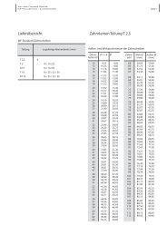
For both 8 mm and 14 mm pitches, the tolerance is ±3 % of the<br />
belt width.<br />
Length tolerances<br />
(in relation to the centre distance of axes; specified in mm)<br />
Belt length Tolerance<br />
h S<br />
(mm)<br />
8 8 3.4 5.9<br />
14 14 6.0 10.2<br />
h t<br />
t<br />
up to 762 +/- 0,30<br />
above 762 to 1016 +/- 0,33<br />
above 1,016 to 1,270 +/- 0,38<br />
above 1,270 to 1,524 +/- 0,41<br />
above 1,524 to 1,778 +/- 0,43<br />
above 1,778 +/– 0.43 mm ± 0.03 mm<br />
for every 254 mm<br />
level for 1778 mm and above<br />
To use <strong>PolyChain®</strong> timing belts with fixed centre distances of axes,<br />
please consult our application engineers.<br />
Weights per metre in kg for <strong>PolyChain®</strong> <strong>GT</strong>2<br />
Pitch<br />
(mm)<br />
Weights per metre in kg for <strong>PolyChain®</strong> Carbon TM<br />
The weights per metre can vary slightly depending on the belt<br />
construction and the tolerance positions.<br />
The ordering designation includes the pitch, pitch length and<br />
belt width:<br />
<strong>PolyChain®</strong> <strong>GT</strong>2<br />
Example: PC-8M<strong>GT</strong> 640 - 12<br />
or PC-14M<strong>GT</strong> 1190 - 37<br />
<strong>PolyChain®</strong> <strong>GT</strong> Carbon TM<br />
Example: PC-8M<strong>GT</strong> 640 - 12 Carbon<br />
or PC-14M<strong>GT</strong> 1190 - 37 Carbon<br />
Pitch<br />
(mm)<br />
Belt width (mm)<br />
12 20 21 36 37 62 68 90 125<br />
8 0.057 - 0.099 0.170 - 0.293 - - -<br />
14 - 0.158 - - 0.292 - 0.536 0.709 0.985<br />
Pitch<br />
(mm)<br />
Belt width (mm)<br />
12 20 21 36 37 62 68 90 125<br />
8 0.056 - 0.099 0.169 - 0.291 - - -<br />
14 - 0.158 - - 0.292 - 0.537 0.711 0.987<br />
Pitch length<br />
(mm)<br />
Width<br />
(mm)<br />
8 M 640 12<br />
14 M 1190 37
<strong>Walther</strong> <strong>Flender</strong> Gruppe<br />
PolyChain ® <strong>GT</strong> <strong>Timing</strong> <strong>Belts</strong><br />
Open-ended model (LongLength)<br />
Pitches<br />
<strong>PolyChain®</strong> <strong>GT</strong>2 Long Length (LL) timing belts are available with<br />
8 mm and 14 mm pitches.<br />
Dimensions and weights<br />
Designation Standard<br />
widths<br />
(mm)<br />
For information about dimensioning for special applications<br />
requiring other dimensions, please consult our application<br />
engineers.<br />
Technical information<br />
Permissible tangential loads in newtons<br />
(8M: 21 mm belt width, 14M: 37 mm belt width)<br />
* Minimum number of teeth 22 (8M) or 28 (14M)<br />
Minimum tensile strength in newtons<br />
Ordering designation<br />
The ordering designation includes the belt width, pitch length<br />
and roll length:<br />
Example:<br />
Weight per<br />
metre in g<br />
(10 mm<br />
belt width)<br />
Number of pulley teeth<br />
Pitch 22 26 28 30 34 38 40 ≥ 44 ≥ 52<br />
8M 3097* 3151 3206 3237 3269 3278<br />
14M 9900* 10 204 10400 10599<br />
Belt width in mm<br />
Pitch 12 20 21 36 37<br />
8M 5787 11 254 19291<br />
14M 20568 38054<br />
PC-21-LL-8M 30M<br />
Maximum<br />
roll<br />
length<br />
t<br />
(mm)<br />
h t<br />
(mm)<br />
Width (mm) Pitch (mm) Roll length (mm)<br />
21 8M 30M<br />
Technical data of the <strong>PolyChain®</strong> Carbon TM Long Length timing<br />
belt is available on request.<br />
h S<br />
(mm)<br />
PC-LL-8M 12 21 36 47.0 30 m 8 3.4 5.9<br />
PC-LL-14M 20 37 37 30 m 14 6.0 10.2<br />
PAGE Page 09
<strong>Walther</strong> <strong>Flender</strong> Gruppe<br />
PolyChain ® <strong>GT</strong> <strong>Timing</strong> <strong>Belts</strong> PAGE 10<br />
<strong>Timing</strong> belt pulleys<br />
<strong>PolyChain®</strong> timing belt pulleys are equipped with special precision-cut<br />
teeth in the gear hobbing process. Only original timing<br />
belt pulley hobbing cutters are used. Only these original tools<br />
ensure a reliable and long-lasting timing belt drive unit.<br />
Only <strong>PolyChain®</strong> timing belts and <strong>PolyChain®</strong> timing belt<br />
pulleys with the same pitch can be used together.<br />
The main features of the timing belt pulley are:<br />
Number of teeth, pitch, width, design<br />
The pitch of the timing belt pulley is measured on the pitch<br />
diameter and is the distance between the centres of two adjacent<br />
hollows. The pulley pitch diameter is always outside the outer diameter<br />
of the timing belt pulley and is congruent with the timing<br />
belt pitch line.<br />
Pitch diameter<br />
Outer diameter<br />
Pitch<br />
<strong>Timing</strong> belt pulleys – standard and custom models<br />
Pitch line<br />
Standard timing belt pulleys are adequate for the requirements of<br />
many drive systems with respect to functionality and space conditions<br />
and are available on a short-term basis.<br />
For heavy-duty, precise drives requiring exact positioning, however,<br />
we recommend custom timing belt pulleys that we manufacture<br />
according to your drawings. Numerous custom teeth are available,<br />
for example for essentially backlash-free or quiet drive systems.<br />
In addition to the standard cast, aluminum and steel timing belt<br />
pulleys, pulleys made of numerous other materials, also with surface<br />
treatment, are available. Please ask our application engineers.<br />
Due to the high specific bearing percentage, standard aluminum<br />
(e.g. AlZn5,5MgCu) should generally be surface treated, for example<br />
hard coated, to ensure high wear resistance.<br />
For shaft and hub connections, we offer an extensive line of<br />
self-centring clamping sets: an overview of models can be found<br />
starting on page 37.<br />
Standard timing belt pulleys<br />
The information on pages 23 to 26 describes our extensive line of<br />
standard timing belt pulleys with and without taper lock clamping<br />
bushes.<br />
Standard pulleys are available for the following belt widths:<br />
Pitch designation 8M 14M<br />
Nominal belt<br />
width in mm<br />
Standard timing belt pulleys are statically balanced; for drive<br />
systems with v > 30 m /s, please ask.<br />
Ordering designation<br />
The ordering designation for <strong>PolyChain®</strong> timing belt pulleys<br />
includes the following:<br />
Pitch Number of<br />
teeth<br />
12 37<br />
21 68<br />
36 90<br />
62 125<br />
8M - 48S - 36 3F<br />
Pulley width designation<br />
(mm)<br />
<strong>Timing</strong> belt pulleys – custom models<br />
Design<br />
8M 48 36 3F<br />
Although the <strong>PolyChain®</strong> standard timing belt pulleys are available<br />
with different numbers of teeth and pulley designs for a broad<br />
range of applications, many applications require custom solutions<br />
with specially designed pulleys.<br />
We have adapted our production facilities to accommodate<br />
such solutions.<br />
We can deliver any timing belt pulley you require, based on your<br />
drawings; special processing, such as grinding, balancing or surface<br />
treatment, is also available.
<strong>Walther</strong> <strong>Flender</strong> Gruppe<br />
PolyChain ® <strong>GT</strong> <strong>Timing</strong> <strong>Belts</strong> PAGE 11<br />
Manufacturing guidelines<br />
Due to the high belt loads and speeds that can occur, the use of<br />
non-wearing materials is preferable.<br />
We offer an extensive selection of pulleys made of steel, sintered<br />
metal and polymer, in addition to high-strength aluminum.<br />
The specified minimum pulley diameters should always be<br />
observed: 60 mm for 8 mm pitch and 130 mm for 14 mm pitch.<br />
Recommended pulley widths<br />
Tooth code<br />
designation<br />
8M<br />
14M<br />
Pulley<br />
width<br />
designation *<br />
Smallest tooth<br />
width<br />
G<br />
mm<br />
Smallest pulley<br />
width with<br />
rim flanges**<br />
E<br />
mm<br />
12 14 18<br />
21 23 27<br />
36 38 42<br />
62 65 70<br />
20 23 27<br />
37 40 46<br />
68 71 77<br />
90 95 101<br />
125 130 136<br />
* Corresponds to the nominal belt width in mm.<br />
** The specified pulley widths include a material allowance for<br />
producing the rim flanges and should always be taken into<br />
account.
<strong>Walther</strong> <strong>Flender</strong> Gruppe<br />
PolyChain ® <strong>GT</strong> <strong>Timing</strong> <strong>Belts</strong><br />
Position & shape tolerances<br />
The tooth surface quality, dimensional accuracy and pitch accuracy<br />
and the position and shape tolerances of the timing belt pulley<br />
have a significant influence on how smooth the drive system<br />
operates.<br />
Since the outer diameter of the pulleys is also surface milled<br />
during the hobbing process, turning produces blanks that are<br />
larger than the finished product.<br />
In finished state, the outer diameter has an especially close<br />
tolerance.<br />
– Tolerances of standard timing belt pulleys<br />
Outer diameter (mm) Permissible deviation (mm)<br />
above to<br />
50 100 + 0.10<br />
101 175 + 0.13<br />
176 300 + 0.15<br />
301 500 + 0.18<br />
501 800 + 0.20<br />
– Tolerances for custom timing belt pulleys<br />
all dimensions in mm<br />
Outer diameter (mm) Permissible Permissible<br />
Rough<br />
above to tolerance concentricity tolerance allowance da+<br />
50 100 + 0.08 0.05<br />
101 150 + 0.10 0.07<br />
151 200 + 0.12 0.1<br />
201 300 + 0.15 0.12 + 1.0 mm<br />
301 500 + 0.18 0.03 pro<br />
501 . . . + 0.20 100 mm<br />
– Run-out tolerance<br />
Outer diameter range<br />
(mm)<br />
Permissible deviations<br />
(mm)<br />
to 101.60 0.10<br />
above 101.60 0.1 + 0.1 mm<br />
to 250.00 per 100 mm outer diameter<br />
0.25 + 0.05 mm<br />
above 251.00 per 100 mm outer diameter<br />
– Bore dimensions of standard pulleys<br />
We recommend a tolerance in the range of IT 7 for the final bore.<br />
– Temperature expansion coefficient a<br />
of the timing belt pulley materials<br />
Thermal effects of the drive system can cause thermal expansion<br />
of the pulley diameters, which can affect the belt<br />
tension. Therefore, you should take into account the following<br />
thermal expansion coefficients in case of extreme tempera ture<br />
fluctuations:<br />
Steel: 12,0 · 10 –6 1/K<br />
Aluminum: 23,5 · 10 –6 1/K<br />
– Balancing<br />
Rotationally symmetric timing belt pulleys machined on all sides<br />
for standard drive systems do not need to be balanced.<br />
High-speed timing belt pulleys for precise drive systems are<br />
balanced according to DIN/ISO 1940 (previously VDZ 2060).<br />
In case of a quality grade of less than 6.3, please contact our<br />
application engineers.<br />
Runout<br />
Concentricity<br />
Outer diameter<br />
PAGE 12
<strong>Walther</strong> <strong>Flender</strong> Gruppe<br />
PolyChain ® <strong>GT</strong> <strong>Timing</strong> <strong>Belts</strong> PAGE 13<br />
Rim flanges<br />
Rim flanges for belt guidance<br />
Poly Chain® timing belt pulley drive systems are designed with<br />
a double flanged pulley for guiding the timing belt. To reduce<br />
costs, the smaller timing belt pulley is frequently provided for this<br />
purpose.<br />
It should be noted, however, that the driven timing belt pulley<br />
should always be equipped with double flanges, since this makes<br />
it easier to guide the slack side. For very large centre distances<br />
of axes (> 8 · d) and transmission ratios of 1 : 3 or higher and for<br />
vertical shaft positions, both timing belt pulleys should have<br />
double flanges.<br />
We offer an extensive standard line of galvanized steel flanges;<br />
please use the rim flange dimensions in the following tables for<br />
your design.<br />
The rim flanges are bevelled for better guidance of the timing<br />
belt when it runs onto the pulley. Straight rim flanges sometimes<br />
have the disadvantage that, if the shaft is not aligned precisely,<br />
the belt tooth can run onto the inside edge of the flange, resulting<br />
in premature wear. Therefore, we do not recommend using straight<br />
rim flanges without a bevel.<br />
Poly Chain® 8M<br />
Number of teeth Code A (mm) B (mm) C (mm) s (mm)<br />
22 18 L 48 54 60 1.5<br />
23 14 H 47 57 63 1.5<br />
24 15 H 51 60.5 66.5 1.5<br />
25 16 H 53 64 71 1.5<br />
26 – 27 17 H 57 68 75 1.5<br />
28 – 29 18 H 60 72 79 1.5<br />
30 19 H 64 76 83 1.5<br />
31 – 32 20 H 68 79 87 1.5<br />
33 21 H 73 84 91 1.5<br />
34 – 35 22 H 76 88 93 1.5<br />
36 23 H 79 91 97 1.5<br />
37 – 38 24 H 82.5 96 103 1.5<br />
39 – 40 25 H 87 100 106 1.5<br />
41 – 42 26 H 91 105 111 1.5<br />
43 27 H 97 109 115 1.5<br />
44 – 45 28 H 99 114 119 1.5<br />
46 – 48 30 H 107 121 127 1.5<br />
49 – 51 32 H 116 129 135 1.5<br />
52 – 53 33 H 120 134 140 1.5<br />
54 – 55 34 H 126 139 146 1.5<br />
56 – 57 36 H 132 145 152 1.5<br />
58 – 61 38 H 140 154 160 1.5<br />
62 – 64 40 H 148 161 168 1.5<br />
65 – 67 42 H 156 170 176 1.5<br />
68 – 70 44 H 164 177 184 1.5<br />
71 – 73 46 H 172 186 192 1.5<br />
74 – 77 48 H 180 195 200 1.5<br />
78 – 83 L216 190 – 216 2<br />
84 – 92 L238 200 – 238 2<br />
93 L260 210 – 260 2.5<br />
94 – 99 L260 S 230 – 260 2<br />
100 – 107 L280 230 – 280 2.5<br />
xmin = 6.0 mm<br />
Ø C ± 0.5<br />
D min = 0.5<br />
Ø B ± 0.5<br />
Ø A ± 0.15<br />
D<br />
8°min<br />
25°max<br />
S<br />
x min.<br />
Outer Ø<br />
D min : Minimum material overlap for functional rolling of rim flange<br />
Note: depending on the angle, the outer edge of the rim flange<br />
may not be flush with the front face of the timing belt pulley!<br />
Poly Chain® 14M<br />
Number of teeth Code A (mm) B (mm) C (mm) s (mm)<br />
28 L138 105 – 138 2.5<br />
29 – 30 L142 90 – 142 2.5<br />
31 – 32 L156 105 – 156 2.5<br />
33 – 34 L172 115 – 172 2.5<br />
35 – 38 L186 130 – 186 2.5<br />
39 – 43 L200 144 – 200 2.5<br />
44 – 46 L215 160 – 215 2.5<br />
47 – 49 L230 190 – 230 2.5<br />
50 – 52 L242 185 – 242 2.5<br />
53 – 55 L260 210 – 260 2.5<br />
56 – 59 L280 230 – 280 2.5<br />
60 – 64 L300 250 – 300 2.5<br />
65 – 68 L320 260 – 320 2.5<br />
69 – 73 L340 280 – 340 2.5<br />
74 – 79 L372 300 – 372 2.5<br />
80 – 84 L385 330 – 385 2.5<br />
85 – 92 L420 360 – 420 2.5<br />
> 92 no standard flange, flange has to be adapted.<br />
xmin = 6.0 mm
<strong>Walther</strong> <strong>Flender</strong> Gruppe<br />
PolyChain ® <strong>GT</strong> <strong>Timing</strong> <strong>Belts</strong> PAGE 14<br />
Assembly & maintenance<br />
Installation<br />
Proper handling during installation of the timing belt is very<br />
important. Avoid bending, twisting, winding or kinking the belts.<br />
Under no circumstances should force be applied to put the timing<br />
belt on the pulleys.<br />
Installation guidelines<br />
For the belt to run straight, it is essential to carefully align the<br />
shafts and timing belt pulleys so they are parallel. Impermissible<br />
deviations from parallel cause different edge tensions in the belt,<br />
causing the belt to run off toward the side with the highest tension<br />
or to run up against the flange. At high speeds, the latter can<br />
cause excessive noise and excessive wear of the belt. In the case of<br />
larger centre distances of axes, it is more difficult to align the shafts<br />
precisely, increasing the tendency for the timing belt to run off to<br />
one side. Therefore, take measures to ensure that the belt does not<br />
run off the face of the timing belt pulleys. It may be necessary to<br />
move the driven pulley slightly.<br />
Electrical conductivity<br />
Tests have shown that <strong>PolyChain®</strong> timing belts do not conduct<br />
electricity under dynamic operating conditions. This can result<br />
in static electricity with uncontrolled malfunctions. If <strong>PolyChain®</strong><br />
timing belts are used in potentially explosive areas, we recommend<br />
taking measures to ensure that no electrical charge can<br />
occur before operating the system. This means that the entire<br />
system has to be properly earthed.<br />
Ambient influences<br />
Temperatures<br />
<strong>PolyChain®</strong> timing belts can generally be used in a temperature<br />
range between –54 °C and +85 °C. For operating conditions outside<br />
of this temperature range, please contact us.<br />
Chemical resistance<br />
Field and lab tests guarantee resistance against many acids, caustic<br />
solutions, grease and oil. Of course, the service life and durability of<br />
the timing belt also depend on the concentration of the substance<br />
to which it is exposed (e.g. droplets, spray or constant immersion).<br />
For special applications, please ask our application engineers.<br />
Adjustment tolerances<br />
Since fixed (non-adjustable) centre distances of axes can be<br />
recommended only for slow-running drive systems, the use of<br />
a <strong>PolyChain®</strong> timing belt drive system requires that the timing<br />
belt can easily be installed and that the belt tension can be<br />
precisely adjusted. The mounting dimension must allow for easy<br />
mounting of the belt on a timing belt pulley with rim flanges.<br />
max. 0.25°<br />
max. 5 min. / 1 m<br />
The minimum dimensions for the respective centre distances of<br />
axes are listed in the tables below. The travel of the centre distance<br />
of axes for mounting and adjustment of the belt tension is shown<br />
in the right column.<br />
Adjustment tolerances without rim flange<br />
Belt length<br />
(mm)<br />
to<br />
1000<br />
from 1000<br />
up to 1780<br />
from 1780<br />
up to 2540<br />
from 2540<br />
up to 3300<br />
from 3300<br />
up to 4600<br />
Travel (mm) for<br />
mounting the<br />
timing belt<br />
Adjustment tolerances with rim flange<br />
Pitch Rim flanges on one<br />
timing belt pulley<br />
(mm)<br />
Travel (mm) for<br />
adjusting the timing<br />
belt tension<br />
1.8 0.8<br />
2.8 0.8<br />
3.3 1.0<br />
4.1 1.0<br />
5.3 1.3<br />
Rim flanges on both<br />
timing belt pulleys<br />
(mm)<br />
8 mm 21.8 33.3<br />
14 mm 31.2 50.0<br />
Fixed centre distance of axes<br />
<strong>Belts</strong> with a pitch of 8M can be used up to a pitch length of<br />
ca. 1,600 mm for slow running drives (n ≤ 100 rpm) with fixed centre<br />
distances of axes; the tolerance for the centre distance of axes<br />
should be within the calculated range of 0 to –0.2 mm. Since the<br />
pulley diameter should also be within close tolerances, please ask<br />
our application engineers.<br />
Idlers<br />
Idlers should only be used on drive systems with a fixed centre<br />
distance of axes and should be mounted on the inside of the slack<br />
side. We recommend using idlers with up to 40 teeth. For larger<br />
diameters, smooth idlers without teeth can also be used. An idler<br />
exerting force on the back should not be used with aramid belts,<br />
since they have a negative effect on the service life due to the<br />
special construction of the timing belts. For carbon belts, the minimum<br />
diameter for outer idlers is 70 mm for a pitch of 8 mm and<br />
150 mm for a pitch of 14 mm. Inner idlers should not be smaller<br />
than the smallest power transmitting timing belt pulley. To maximize<br />
the number of meshing teeth on the small timing belt pulley,<br />
it is recommended to position the idler near the large pulley on<br />
the slack side. If the belt touches the idler with only one tooth, this<br />
can result in high noise levels. It is better to have several belt teeth<br />
mesh with the pulley.
<strong>Walther</strong> <strong>Flender</strong> Gruppe<br />
PolyChain ® <strong>GT</strong> <strong>Timing</strong> <strong>Belts</strong> PAGE 15<br />
Belt tension<br />
The Poly Chain® timing belt needs a certain tension during operation<br />
to maintain reliable engagement of the teeth also under<br />
intermittent loads and temporary overloads. Unnecessarily high<br />
initial tension reduces the service life of the drive system, increases<br />
wear on the bearings and the teeth, and also increases the noise<br />
level. Insufficient tension can prevent the belt teeth from meshing<br />
properly in the pulley teeth, which can even cause the belt to<br />
skip in case of an overload. Depending on the application and the<br />
particular dynamic peak loads, the belt tension can deviate from<br />
the calculated initial tension, so that the calculation provided here<br />
should be used only as a recommendation for standard applications.<br />
This applies especially to drive systems with extreme impact<br />
and pulse loads; in this case, please contact us.<br />
Calculation of the static initial load<br />
F St = K · P + m · v 2<br />
v<br />
F St [N] = Static initial tension<br />
P [kW] = Installed motor power output<br />
v [m/s] = Belt speed<br />
m = Factor for weight per metre, see table<br />
K = Constant for compensating for<br />
impact loads<br />
K = 600 max. initial tension for compensating for pulse loads<br />
Pitch Belt width (mm) m Y<br />
8 mm 12 0.057 80<br />
21 0.098 140<br />
36 0.167 240<br />
62 0.290 413<br />
14 mm 20 0.158 245<br />
37 0.291 454<br />
68 0.536 834<br />
90 0.711 1103<br />
125 0.986 1530<br />
Table: Calculation factors for belt tension<br />
If the transmission capacity is significantly higher than the calculated<br />
capacity of the belt, the calculations can result in incorrect<br />
belt tensions. In this case, please use the minimum initial tensions<br />
specified in the following table:<br />
Pitch Belt width (mm)<br />
8 mm<br />
14 mm<br />
Min. F st<br />
Values (N)<br />
12 125<br />
21 220<br />
36 375<br />
62 645<br />
20 530<br />
37 980<br />
68 1800<br />
90 2380<br />
125 3310<br />
Table: Minimum initial tension of <strong>PolyChain®</strong> timing belts<br />
Checking the belt tension<br />
Two methods can be used for checking the belt tension:<br />
1. Frequency measurement and 2. Test load method<br />
1. Frequency measurement<br />
A precise method for pre-setting the correct belt tension is to<br />
measure the frequency with the WF Tension Meter (Figure 1) or<br />
the Gates-Sonic Tension Meter (Figure 2). With a sensing head<br />
that is held above the installed belt it is possible to measure the<br />
frequency at the pre-tensioned belt in order to achieve the optimum<br />
belt tension.<br />
The calculated oscillation frequency f [Hz] depends on the freely<br />
oscillating span length L [m], the static initial tension load FSt [N]<br />
and the weight per meter m [kg/m] of the belt and corresponds<br />
to the relationship<br />
f = 1 · √ F St<br />
2 · L m<br />
For a detailed description of the instruments and detailed calculation<br />
documentation, please contact our application engineers.<br />
2. Test load method<br />
Calculation of deflection<br />
S = √A2 – [ dwG – d 2<br />
wk ]<br />
2<br />
S : Span length for test force measurement (mm)<br />
d : Deflection (mm)<br />
dwk : Pitch diameter of the small pulley (mm)<br />
dwG : Pitch diameter of the large pulley (mm)<br />
FP : Test force (N)<br />
A : Centre distance of axes (mm); separate tables are available<br />
for the calculation and will be provided on request.<br />
If the span tension is set correctly, the deflection is<br />
d ~ 1 / 100 · S<br />
Calculation of test force<br />
Figure 1:<br />
WF Tension Meter<br />
S<br />
d<br />
FP<br />
Figure 2:<br />
Gates Sonic Tension<br />
Meter 507C<br />
F St + S · Y F P : Test force (N)<br />
F P = l w F St : Static initial tension<br />
25 l w : Pitch length (mm)<br />
Y : Constant (see table)<br />
Adjusting the initial tension<br />
For the calculated test force, the deflection should be ca. 1/100 of<br />
the span length [mm] of the test force measurement. It may be<br />
necessary to correct the belt tension.
<strong>Walther</strong> <strong>Flender</strong> Gruppe<br />
PolyChain ® <strong>GT</strong> <strong>Timing</strong> <strong>Belts</strong> PAGE 16<br />
Storage & maintenance<br />
<strong>PolyChain®</strong> timing belts require no special maintenance. During the wear-in period of heavy-duty drive systems there may be some<br />
reduction in the belt tension; in this case, it is necessary to retighten the belts only once with 50 % of the original initial tension.<br />
When storing belts, they should never be kinked or folded tightly, because this can damage the tensile members. Therefore, we recommend<br />
that timing belts be stored in the original package until needed; during storage, belts should be protected from extreme temperatures,<br />
humidity and UV radiation.<br />
Clamping elements<br />
For secure fastening of the timing belt pulley to the shaft, you can<br />
use the conventional feather key connection or any number of<br />
frictionally engaged, removable clamping elements for all standard<br />
bore dimensions.<br />
In addition to the TL (TaperLock®) bushes used primarily for standard<br />
pulleys, we offer an extensive line of cylindrical inner and outer<br />
clamping sets, which are especially suitable to fulfil requirements<br />
for optimal true running properties.<br />
Please note the required minimum hub and minimum wall thicknesses<br />
to ensure reliable use of the clamping sets; please contact<br />
us before using aluminum pulleys.<br />
Further information on our clamping sets can be found starting<br />
on page 33.<br />
Advantages of the positive locking cylindrical clamping<br />
elements:<br />
– Easy mounting and removal<br />
Mounting and removal by tightening or loosening the clamping<br />
screws using conventional tools. A precise torque can be achieved<br />
by using a torque wrench.<br />
Oil the clamping set lightly when mounting it. Do not use oil containing<br />
molybdenum disulfide and do not use grease.<br />
– Backlash-free connection<br />
The clamping sets provide a positive-locking, backlash-free connection<br />
that can be released at any time.<br />
– Large machining tolerances<br />
The following fitting combinations are recommended:<br />
Tolerances in the shaft diameter: h 7/h 9<br />
Tolerances in the hub bore diameter: H 7/H 9<br />
Surface roughness ≤ RZ 16<br />
The runout error is between 0.02 and 0.04 mm, depending on the<br />
model; all clamping elements listed here are self-centring.<br />
– High fatigue strength<br />
No weakening of the shaft and pulley bore by keyways.<br />
– Easy adjustment<br />
Since no profile end mating is necessary, the components can<br />
be fastened at a precise angle in any required position.<br />
– Overload protection<br />
If the maximum torque is exceeded, slippage of the clamping<br />
set prevents damage to the connected parts. Repeated slipping<br />
should be avoided.<br />
– Economical connection<br />
An economical shaft/hub connection, due to ease of<br />
manufacturing the smooth cylindrical shaft and bore fit.
<strong>Walther</strong> <strong>Flender</strong> Gruppe<br />
PolyChain ® <strong>GT</strong> <strong>Timing</strong> <strong>Belts</strong> PAGE 17<br />
Technical data<br />
Power output values & belt lengths<br />
<strong>Timing</strong> belt pitch PC - 8M<strong>GT</strong> and PC - 8M<strong>GT</strong> Carbon<br />
Calculation of the dimensions and design of belt drive units can<br />
be based on the motor side (motor power output) and on the<br />
load side (load collectives). Both calculations – depending on<br />
the existing safety factors, desired service life or any load- side<br />
efficiency losses – can result in designs for drive systems with<br />
Maximum permissible tangential loads<br />
The values listed in the following tables represent the operationally<br />
useable tangential loads. The listed values apply to quasistatic<br />
loads, i.e. for low speed ranges (n ≤ 100 rpm) with the use of<br />
timing belt pulleys with at least 34 teeth.<br />
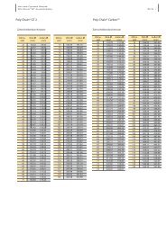
<strong>PolyChain®</strong> <strong>GT</strong>2<br />
Belt width (mm) 12 21 36 62<br />
Fzul (N) 2012 3521 6037 10397<br />
Power output in kW / 12 mm belt width<br />
Note: The following power output data was obtained in extensive<br />
series of tests on the basis of defined service life values and<br />
includes safety factors that were defined internally beforehand<br />
to achieve the corresponding service life. Therefore, the power<br />
<strong>PolyChain®</strong> <strong>GT</strong>2<br />
Speed<br />
of the<br />
small<br />
pulley<br />
different overall widths. In addition to the load value calculation,<br />
therefore, we also recommend that you use the following power<br />
output table to compare the actual tangential loads with the<br />
maximum permissible loads.<br />
The initial tensions for mounting of the belts are already included<br />
in the power output values and do not have to be subtracted from<br />
the listed values.<br />
<strong>PolyChain®</strong> <strong>GT</strong> Carbon <br />
Power output of the small timing belt pulley<br />
Belt width (mm) 12 21 36 62<br />
Fzul (N) 2404 4208 7213 12431<br />
output data cannot be compared directly with data of other<br />
manufacturers; if you have any questions, please contact our<br />
application engineers.<br />
22 25 28 30 32 34 36 38 40 45 48 50 56 60 64 75 80<br />
56.02 63.66 71.30 76.39 81.49 86.58 91.67 96.77 101.86 114.59 122.23 127.32 142.60 152.79 162.97 190.99 203.72<br />
10 0.10 0.12 0.14 0.15 0.16 0.17 0.18 0.19 0.20 0.23 0.24 0.25 0.29 0.31 0.33 0.39 0.41<br />
20 0.16 0.18 0.21 0.23 0.24 0.26 0.28 0.29 0.31 0.35 0.38 0.40 0.45 0.48 0.51 0.60 0.64<br />
40 0.25 0.30 0.34 0.37 0.40 0.43 0.46 0.48 0.51 0.58 0.63 0.66 0.74 0.80 0.85 1.00 1.07<br />
60 0.34 0.40 0.46 0.50 0.54 0.58 0.62 0.66 0.70 0.80 0.86 0.90 1.02 1.09 1.17 1.38 1.48<br />
100 0.51 0.60 0.70 0.76 0.82 0.88 0.94 1.00 1.07 1.22 1.31 1.37 1.54 1.66 1.78 2.10 2.25<br />
200 0.90 1.07 1.24 1.35 1.47 1.58 1.69 1.80 1.91 2.19 2.35 2.46 2.78 3.00 3.21 3.79 4.05<br />
300 1.26 1.51 1.75 1.91 2.07 2.23 2.39 2.55 2.71 3.10 3.33 3.49 3.95 4.26 4.56 5.39 5.76<br />
400 1.61 1.92 2.24 2.45 2.66 2.86 3.07 3.27 3.48 3.98 4.28 4.48 5.08 5.47 5.87 6.93 7.41<br />
500 1.94 2.33 2.71 2.97 3.22 3.47 3.72 3.97 4.22 4.84 5.21 5.45 6.18 6.66 7.13 8.43 9.02<br />
600 2.26 2.72 3.17 3.47 3.77 4.07 4.36 4.66 4.95 5.68 6.11 6.39 7.25 7.81 8.37 9.90 10.58<br />
700 2.58 3.11 3.63 3.97 4.31 4.65 4.99 5.33 5.66 6.50 6.99 7.32 8.30 8.94 9.59 11.33 12.12<br />
730 2.67 3.22 3.76 4.12 4.47 4.83 5.18 5.53 5.87 6.74 7.25 7.59 8.61 9.28 9.95 11.76 12.58<br />
800 2.89 3.48 4.07 4.46 4.84 5.23 5.61 5.99 6.36 7.30 7.86 8.23 9.33 10.06 10.78 12.75 13.63<br />
900 3.19 3.85 4.50 4.93 5.36 5.79 6.21 6.63 7.05 8.09 8.71 9.12 10.35 11.15 11.96 14.13 15.11<br />
1,000 3.49 4.22 4.93 5.41 5.88 6.34 6.81 7.27 7.73 8.88 9.56 10.01 11.35 12.23 13.11 15.50 16.58<br />
1,200 4.07 4.93 5.77 6.33 6.88 7.43 7.98 8.53 9.07 10.41 11.21 11.74 13.31 14.35 15.38 18.18 19.44<br />
1,400 4.64 5.62 6.59 7.23 7.86 8.50 9.12 9.75 10.37 11.91 12.82 13.43 15.23 16.42 17.60 20.79 22.22<br />
1,460 4.81 5.82 6.83 7.49 8.15 8.81 9.46 10.11 10.76 12.35 13.30 13.93 15.80 17.03 18.25 21.56 23.04<br />
1,600 5.19 6.30 7.39 8.11 8.83 9.54 10.24 10.95 11.65 13.38 14.41 15.09 17.11 18.44 19.76 23.34 24.94<br />
1,800 5.73 6.96 8.17 8.97 9.77 10.56 11.34 12.12 12.90 14.82 15.96 16.71 18.95 20.42 21.88 25.83 27.58<br />
2,000 6.27 7.61 8.94 9.82 10.69 11.56 12.42 13.28 14.13 16.23 17.48 18.30 20.75 22.36 23.96 28.25 30.16<br />
2,400 7.30 8.88 10.44 11.48 12.50 13.52 14.53 15.53 16.52 18.98 20.44 21.40 24.25 26.13 27.97 32.93 35.13<br />
2,800 8.29 10.11 11.90 13.08 14.25 15.41 16.57 17.71 18.85 21.65 23.30 24.39 27.63 29.74 31.82 37.38 39.82<br />
2,880 8.49 10.35 12.19 13.40 14.60 15.79 16.97 18.14 19.30 22.17 23.86 24.98 28.28 30.44 32.57 38.24 40.73<br />
3,200 9.26 11.30 13.31 14.64 15.95 17.26 18.55 19.83 21.10 24.22 26.07 27.28 30.87 33.20 35.50 41.58<br />
3,500 9.97 12.18 14.35 15.78 17.20 18.60 20.00 21.38 22.74 26.10 28.08 29.38 33.21 35.70 38.14<br />
4,000 11.11 13.59 16.03 17.63 19.22 20.79 22.34 23.88 25.40 29.12 31.31 32.75 36.96 39.68<br />
4,500 12.22 14.97 17.66 19.43 21.17 22.90 24.60 26.29 27.95 32.02 34.39 35.95<br />
5,000 13.30 16.30 19.23 21.16 23.06 24.93 26.78 28.60 30.40 34.78 37.32 38.98<br />
5,500 14.34 17.58 20.76 22.83 24.88 26.89 28.87 30.83 32.74 37.40<br />
Max. power output = (Table output + additional output) x length factor x width factor
<strong>Walther</strong> <strong>Flender</strong> Gruppe<br />
PolyChain ® <strong>GT</strong> <strong>Timing</strong> <strong>Belts</strong> PAGE 18<br />
<strong>PolyChain®</strong> <strong>GT</strong> Carbon <br />
Power output of the small timing belt pulley<br />
Speed<br />
Number of teeth<br />
of the 22 25 28 30 32 34 36 38 40 45 48 50 56 60 64 75 80<br />
small<br />
pulley<br />
56.02 63.66 71.30 76.39 81.49 86.58 91.67<br />
Pitch diameter<br />
96.77 101.86 114.59 122.23 127.32 142.60 152.79 162.97 190.99 203.72<br />
10 0.11 0.13 0.15 0.17 0.18 0.19 0.21 0.22 0.23 0.26 0.28 0.30 0.34 0.36 0.39 0.46 0.49<br />
20 0.17 0.21 0.24 0.26 0.28 0.31 0.33 0.35 0.37 0.42 0.45 0.48 0.54 0.58 0.62 0.74 0.79<br />
40 0.29 0.34 0.40 0.44 0.48 0.51 0.55 0.59 0.63 0.72 0.77 0.81 0.92 0.99 1.07 1.27 1.36<br />
60 0.39 0.47 0.55 0.61 0.66 0.71 0.76 0.82 0.87 1.00 1.08 1.13 1.28 1.39 1.49 1.77 1.89<br />
100 0.59 0.72 0.84 0.93 1.01 1.09 1.17 1.26 1.34 1.54 1.66 1.74 1.98 2.14 2.30 2.74 2.93<br />
200 1.06 1.29 1.53 1.68 1.83 1.99 2.14 2.29 2.44 2.82 3.05 3.20 3.64 3.94 4.24 5.04 5.41<br />
300 1.50 1.84 2.17 2.40 2.62 2.84 3.06 3.28 3.50 4.05 4.37 4.59 5.23 5.66 6.09 7.25 7.78<br />
400 1.92 2.36 2.80 3.09 3.38 3.67 3.95 4.24 4.53 5.24 5.66 5.94 6.78 7.34 7.89 9.41 10.09<br />
500 2.33 2.87 3.41 3.77 4.12 4.47 4.83 5.18 5.53 6.40 6.92 7.27 8.30 8.98 9.66 11.51 12.35<br />
600 2.73 3.37 4.01 4.43 4.85 5.27 5.68 6.10 6.51 7.54 8.16 8.57 9.78 10.59 11.39 13.59 14.58<br />
700 3.12 3.86 4.59 5.08 5.56 6.05 6.53 7.01 7.48 8.67 9.38 9.85 11.25 12.18 13.11 15.63 16.77<br />
800 3.50 4.34 5.17 5.72 6.27 6.81 7.36 7.90 8.44 9.78 10.58 11.11 12.70 13.75 14.79 17.65 18.93<br />
900 3.88 4.81 5.74 6.35 6.96 7.57 8.18 8.78 9.38 10.88 11.77 12.36 14.13 15.30 16.46 19.64 21.07<br />
1,000 4.25 5.28 6.30 6.98 7.65 8.32 8.99 9.65 10.32 11.96 12.95 13.60 15.54 16.83 18.11 21.61 23.18<br />
1,200 4.98 6.20 7.41 8.21 9.00 9.80 10.59 11.37 12.16 14.10 15.27 16.04 18.33 19.86 21.37 25.49 27.34<br />
1,400 5.69 7.10 8.49 9.41 10.33 11.25 12.16 13.06 13.97 16.21 17.55 18.43 21.08 22.83 24.57 29.30 31.43<br />
1,600 6.39 7.98 9.56 10.60 11.64 12.67 13.70 14.73 15.75 18.28 19.79 20.79 23.78 25.75 27.71 33.04 35.44<br />
1,800 7.08 8.85 10.61 11.77 12.93 14.08 15.22 16.37 17.50 20.32 22.00 23.12 26.44 28.63 30.81 36.72 39.38<br />
2,000 7.75 9.71 11.64 12.92 14.20 15.46 16.73 17.98 19.23 22.34 24.18 25.41 29.06 31.47 33.86 40.34 43.24<br />
2,400 9.07 11.38 13.67 15.18 16.69 18.19 19.68 21.16 22.63 26.29 28.46 29.91 34.19 37.02 39.82 47.39 50.77<br />
2,800 10.36 13.02 15.65 17.39 19.12 20.84 22.56 24.26 25.95 30.15 32.64 34.29 39.19 42.41 45.60 54.20 58.02<br />
3,200 11.61 14.61 17.59 19.55 21.51 23.45 25.38 27.29 29.20 33.92 36.71 38.56 44.05 47.65 51.21 60.76<br />
3,500 12.53 15.79 19.01 21.14 23.26 25.36 27.45 29.53 31.59 36.69 39.70 41.70 47.61 51.48 55.30<br />
4,000 14.03 17.71 21.34 23.74 26.13 28.49 30.84 33.17 35.48 41.19 44.56 46.79 53.36 57.66<br />
4,500 15.49 19.58 23.62 26.28 28.92 31.54 34.14 36.71 39.27 45.56 49.27 51.71<br />
5,000<br />
5,500<br />
16.92<br />
18.31<br />
21.41<br />
23.19<br />
25.84<br />
28.00<br />
28.76<br />
31.17<br />
31.65<br />
34.31<br />
34.51<br />
37.41<br />
37.35<br />
40.48<br />
40.16<br />
43.51<br />
42.95<br />
46.52<br />
49.79<br />
53.87<br />
53.81 56.45<br />
Max. power output = (Table output + additional output) x length factor x width factor<br />
Design information on page 23<br />
Additional power output [kW] for step-down ratio<br />
<strong>PolyChain®</strong> <strong>GT</strong>2:<br />
Speed of the<br />
small pulley<br />
1<br />
to<br />
1.04<br />
1.05<br />
to<br />
1.11<br />
1.12<br />
to<br />
1.19<br />
1.2<br />
to<br />
1.3<br />
1.31<br />
to<br />
1.45<br />
1.46<br />
to<br />
1.65<br />
1.66<br />
to<br />
1.99<br />
2<br />
to<br />
2.63<br />
2.64<br />
to<br />
4.47<br />
200 0.00 0.01 0.03 0.04 0.05 0.07 0.08 0.09 0.10<br />
300 0.00 0.02 0.04 0.06 0.08 0.10 0.12 0.14 0.16<br />
400 0.00 0.03 0.05 0.08 0.10 0.13 0.16 0.18 0.21<br />
500 0.00 0.03 0.07 0.10 0.13 0.16 0.20 0.23 0.26<br />
600 0.00 0.04 0.08 0.12 0.16 0.20 0.23 0.27 0.31<br />
700 0.00 0.05 0.09 0.14 0.18 0.23 0.27 0.32 0.36<br />
730 0.00 0.05 0.09 0.14 0.19 0.24 0.28 0.33 0.38<br />
800 0.00 0.05 0.10 0.16 0.21 0.26 0.31 0.36 0.42<br />
900 0.00 0.06 0.12 0.18 0.23 0.29 0.35 0.41 0.47<br />
1,000 0.00 0.06 0.13 0.20 0.26 0.33 0.39 0.46 0.52<br />
1,200 0.00 0.08 0.16 0.23 0.31 0.39 0.47 0.55 0.62<br />
1,400 0.00 0.09 0.18 0.27 0.36 0.46 0.55 0.64 0.73<br />
1,460 0.00 0.09 0.19 0.28 0.38 0.47 0.57 0.66 0.76<br />
1,600 0.00 0.10 0.21 0.31 0.42 0.52 0.62 0.73 0.83<br />
1,800 0.00 0.12 0.23 0.35 0.47 0.59 0.70 0.82 0.94<br />
2,000 0.00 0.13 0.26 0.39 0.52 0.65 0.78 0.91 1.04<br />
2,400 0.00 0.16 0.31 0.47 0.62 0.78 0.94 1.09 1.25<br />
2,800 0.00 0.18 0.36 0.55 0.73 0.91 1.09 1.27 1.46<br />
2,880 0.00 0.19 0.37 0.56 0.75 0.94 1.12 1.31 1.50<br />
3,200 0.00 0.21 0.42 0.62 0.83 1.04 1.25 1.46 1.66<br />
3,500 0.00 0.23 0.46 0.68 0.91 1.14 1.37 1.59 1.82<br />
4,000 0.00 0.26 0.52 0.78 1.04 1.30 1.56 1.82 2.08<br />
4,500 0.00 0.29 0.59 0.88 1.17 1.46 1.76 2.05 2.34<br />
5,000 0.00 0.32 0.65 0.98 1.30 1.63 1.95 2.28 2.60<br />
5,500 0.00 0.36 0.72 1.07 1.43 1.79 2.15 2.50 2.86<br />
Additional power output [kW] for step-down ratio<br />
<strong>PolyChain®</strong> Carbon TM:<br />
Speed of the<br />
small pulley<br />
1.00 1.02 1.05 1.10 1.15 1.21 1.30 1.43 1.64 2.15<br />
1.02 1.05 1.10 1.15 1.21 1.30 1.43 1.64 2.15<br />
and<br />
over<br />
20 0.00 0.00 0.00 0.00 0.00 0.01 0.01 0.01 0.01 0.01<br />
40 0.00 0.00 0.00 0.01 0.01 0.01 0.01 0.02 0.02 0.02<br />
60 0.00 0.00 0.01 0.01 0.01 0.02 0.02 0.02 0.03 0.03<br />
100 0.00 0.01 0.01 0.02 0.02 0.03 0.04 0.04 0.05 0.05<br />
200 0.00 0.01 0.02 0.04 0.05 0.06 0.07 0.08 0.09 0.11<br />
300 0.00 0.02 0.04 0.05 0.07 0.09 0.11 0.12 0.14 0.16<br />
400 0.00 0.02 0.05 0.07 0.09 0.12 0.14 0.17 0.19 0.21<br />
500 0.00 0.03 0.06 0.09 0.12 0.15 0.18 0.21 0.24 0.27<br />
600 0.00 0.04 0.07 0.11 0.14 0.18 0.21 0.25 0.28 0.32<br />
700 0.00 0.04 0.08 0.12 0.17 0.21 0.25 0.29 0.33 0.37<br />
800 0.00 0.05 0.09 0.14 0.19 0.24 0.28 0.33 0.38 0.43<br />
900 0.00 0.05 0.11 0.16 0.21 0.27 0.32 0.37 0.43 0.48<br />
1,000 0.00 0.06 0.12 0.18 0.24 0.30 0.36 0.42 0.47 0.53<br />
1,200 0.00 0.07 0.14 0.21 0.28 0.36 0.43 0.50 0.57 0.64<br />
1,400 0.00 0.08 0.17 0.25 0.33 0.42 0.50 0.58 0.66 0.75<br />
1,600 0.00 0.10 0.19 0.29 0.38 0.47 0.57 0.66 0.76 0.85<br />
1,800 0.00 0.11 0.21 0.32 0.43 0.53 0.64 0.75 0.85 0.96<br />
2,000 0.00 0.12 0.24 0.36 0.47 0.59 0.71 0.83 0.95 1.07<br />
2,400 0.00 0.14 0.28 0.43 0.57 0.71 0.85 1.00 1.14 1.28<br />
2,800 0.00 0.17 0.33 0.50 0.66 0.83 1.00 1.16 1.33 1.50<br />
3,200 0.00 0.19 0.38 0.57 0.76 0.95 1.14 1.33 1.52 1.71<br />
3,500 0.00 0.21 0.41 0.62 0.83 1.04 1.25 1.45 1.66 1.87<br />
4,000 0.00 0.24 0.47 0.71 0.95 1.19 1.42 1.66 1.90 2.14<br />
4,500 0.00 0.27 0.53 0.80 1.07 1.34 1.60 1.87 2.14 2.40<br />
5,000 0.00 0.30 0.59 0.89 1.19 1.48 1.78 2.08 2.37 2.67<br />
5,500 0.00 0.33 0.65 0.98 1.30 1.63 1.96 2.28 2.61 2.94
<strong>Walther</strong> <strong>Flender</strong> Gruppe<br />
PolyChain ® <strong>GT</strong> <strong>Timing</strong> <strong>Belts</strong> PAGE 19<br />
Standard lengths and length correction<br />
factors S 6<br />
Standard widths 12, 21, 36, 62 mm<br />
Pitch length<br />
(mm)<br />
Length<br />
correction<br />
factor<br />
Number<br />
of teeth<br />
640 0.79 80<br />
720 0.83 90<br />
800 0.87 100<br />
896 0.91 112<br />
960 0.94 120<br />
1,000 0.96 125<br />
1,040 0.97 130<br />
1,120 1.00 140<br />
1,200 1.03 150<br />
1,224 1.03 153<br />
1,280 1.05 160<br />
1,440 1.10 180<br />
1,600 1.14 200<br />
1,760 1.17 220<br />
1,792 1.18 224<br />
2,000 1.22 250<br />
2,200 1.26 275<br />
2,240 1.26 280<br />
2,400 1.29 300<br />
2,520 1.31 315<br />
2,600 1.32 325<br />
2,800 1.35 350<br />
2,840 1.36 355<br />
3,048 1.38 381<br />
3,200 1.40 400<br />
3,600 1.45 450<br />
4,000 1.49 500<br />
4,400 1.52 550<br />
4,480 1.53 560<br />
Width factor S 7<br />
Belt width 12 21 36 62<br />
Width factor 1 1.75 3.00 5.17<br />
<strong>Timing</strong> belts in custom lengths*<br />
Number<br />
of teeth<br />
Length<br />
(mm)<br />
Number<br />
of teeth<br />
Length<br />
(mm)<br />
31 248 57 456<br />
36 288 60 480<br />
44 352 68 544<br />
52 416 76 608<br />
* Length correction factors and permissible power output data<br />
available on request; may necessitate longer delivery times and<br />
minimum purchase quantities.<br />
<strong>Timing</strong> belt pulley diameter<br />
Number<br />
of teeth<br />
Pitch ø<br />
(mm)<br />
Outer ø<br />
(mm)<br />
22 56.02 54.42<br />
23 58.57 56.97<br />
24 61.12 59.52<br />
25 63.66 62.06<br />
26 66.21 64.61<br />
27 68.75 67.15<br />
28 71.30 69.70<br />
29 73.85 72.25<br />
30 76.39 74.79<br />
31 78.94 77.34<br />
32 81.49 79.89<br />
33 84.03 82.43<br />
34 86.58 84.98<br />
35 89.13 87.53<br />
36 91.67 90.07<br />
37 94.22 92.62<br />
38 96.77 95.17<br />
39 99.31 97.71<br />
40 101.86 100.26<br />
41 104.41 102.81<br />
42 106.95 105.35<br />
43 109.50 107.90<br />
44 112.05 110.44<br />
45 114.59 112.99<br />
46 117.14 115.54<br />
47 119.68 118.08<br />
48 122.23 120.63<br />
49 124.78 123.18<br />
50 127.32 125.72<br />
51 129.87 128.27<br />
52 132.42 130.82<br />
53 134.96 133.36<br />
54 137.51 135.91<br />
55 140.06 138.46<br />
56 142.60 141.00<br />
57 145.15 143.55<br />
58 147.70 146.10<br />
59 150.24 148.64<br />
60 152.79 151.19<br />
61 155.33 153.74<br />
62 157.88 156.28<br />
63 160.43 158.83<br />
64 162.97 161.37<br />
65 165.52 163.92<br />
66 168.07 166.47<br />
67 170.61 169.01<br />
68 173.16 171.56<br />
69 175.71 174.11<br />
70 178.25 176.65<br />
71 180.80 179.20<br />
Number<br />
of teeth<br />
Pitch ø<br />
(mm)<br />
Outer ø<br />
(mm)<br />
72 183.35 181.75<br />
73 185.89 184.29<br />
74 188.44 186.84<br />
75 190.99 189.39<br />
76 193.53 191.93<br />
77 196.08 194.48<br />
78 198.62 197.03<br />
79 201.17 199.57<br />
80 203.72 202.12<br />
81 206.26 204.66<br />
82 208.81 207.21<br />
83 211.36 209.76<br />
84 213.90 212.30<br />
85 216.45 214.85<br />
86 219.00 217.40<br />
87 221.54 219.94<br />
88 224.09 222.49<br />
89 226.64 225.04<br />
90 229.18 227.58<br />
91 231.73 230.13<br />
92 234.28 232.68<br />
93 236.82 235.22<br />
94 239.37 237.77<br />
95 241.92 240.32<br />
96 244.46 242.86<br />
97 247.01 245.41<br />
98 249.55 247.95<br />
99 252.10 250.50<br />
100 254.65 253.05<br />
101 257.19 255.59<br />
102 259.74 258.14<br />
103 262.29 260.69<br />
104 264.83 263.23<br />
105 267.38 265.78<br />
106 269.93 268.33<br />
107 272.47 270.87<br />
108 275.02 273.42<br />
109 277.57 275.97<br />
110 280.11 278.51<br />
111 282.66 281.06<br />
112 285.21 283.61<br />
113 287.75 286.15<br />
114 290.30 288.70<br />
115 292.85 291.24<br />
116 295.39 293.79<br />
117 297.94 296.36<br />
118 300.48 298.88<br />
119 303.03 301.43<br />
120 305.58 303.98
<strong>Walther</strong> <strong>Flender</strong> Gruppe<br />
PolyChain ® <strong>GT</strong> <strong>Timing</strong> <strong>Belts</strong> PAGE 20<br />
<strong>Timing</strong> belt pitch PC – 14M<strong>GT</strong> and PC – 14M<strong>GT</strong> Carbon<br />
Calculation of the dimensions and design of belt drive units can be<br />
based on the motor side (motor power output) and on the load<br />
side (load collectives). Both calculations – depending on the existing<br />
safety factors, desired service life or any load-side efficiency<br />
losses – can result in designs for drive systems with different over-<br />
Maximum permissible tangential loads<br />
The values listed in the following tables represent the operationally<br />
useable tangential loads. The listed values apply to quasistatic<br />
loads, i.e. for low speed ranges (n ≤ 100 rpm) with the use of<br />
timing belt pulleys with at least 34 teeth.<br />
<strong>PolyChain®</strong> <strong>GT</strong>2<br />
Belt width (mm) 37 68 90 125<br />
Fzul (N) 11289 20747 27460 38138<br />
Power output in kW / 20 mm belt width<br />
Note: The following power output data was obtained in extensive<br />
series of tests on the basis of defined service life values and<br />
includes safety factors that were defined internally beforehand<br />
to achieve the corresponding service life. Therefore, the power<br />
Poly Chain® <strong>GT</strong>2<br />
Speed of the<br />
small pulley<br />
Max. power output = (Table output + additional output) x length factor x width factor<br />
Design information on page 23<br />
all widths. In addition to the load value calculation, therefore,<br />
we also recommend that you use the following power output<br />
table to compare the actual tangential loads with the maximum<br />
permissible loads.<br />
The initial tensions for mounting of the belts are already included<br />
in the power output values and do not have to be subtracted from<br />
the listed values.<br />
<strong>PolyChain®</strong> <strong>GT</strong> Carbon<br />
Belt width (mm) 37 68 90 125<br />
Fzul (N) 13829 25416 33639 46720<br />
output data cannot be compared directly with data of other<br />
manufacturers; if you have any questions, please contact our<br />
application engineers.<br />
Power output of the small timing belt pulley<br />
Number of teeth<br />
28 30 32 34 36 38 40 44 48 50 56 60 64<br />
Pitch diameter<br />
124.78 133.69 142.60 151.52 160.43 169.34 178.25 196.08 213.90 222.82 249.55 267.38 285.21<br />
10 0.72 0.77 0.83 0.89 0.95 1.00 1.06 1.17 1.29 1.34 1.51 1.62 1.73<br />
20 1.10 1.19 1.29 1.38 1.47 1.56 1.65 1.83 2.01 2.10 2.36 2.54 2.71<br />
40 1.80 1.95 2.10 2.26 2.41 2.56 2.71 3.02 3.32 3.46 3.91 4.20 4.50<br />
80 3.05 3.32 3.59 3.86 4.13 4.39 4.66 5.18 5.71 5.97 6.74 7.25 7.76<br />
100 3.64 3.97 4.30 4.62 4.94 5.26 5.58 6.21 6.84 7.15 8.08 8.70 9.31<br />
200 6.40 6.99 7.57 8.16 8.74 9.31 9.88 11.02 12.15 12.71 14.38 15.49 16.58<br />
300 8.95 9.78 10.62 11.44 12.26 13.08 13.89 15.51 17.11 17.90 20.26 21.83 23.38<br />
400 11.36 12.44 13.50 14.56 15.62 16.67 17.71 19.78 21.83 22.85 25.87 27.87 29.86<br />
500 13.68 14.98 16.28 17.57 18.85 20.12 21.39 23.90 26.38 27.61 31.28 33.70 36.10<br />
600 15.92 17.45 18.97 20.48 21.98 23.47 24.95 27.89 30.79 32.24 36.53 39.35 42.16<br />
700 18.09 19.84 21.58 23.30 25.02 26.72 28.41 31.77 35.09 36.74 41.63 44.86 48.05<br />
730 18.73 20.55 22.35 24.14 25.92 27.68 29.44 32.92 36.36 38.07 43.14 46.48 49.79<br />
800 20.21 22.17 24.12 26.06 27.99 29.90 31.80 35.56 39.29 41.13 46.61 50.22 53.80<br />
900 22.27 24.45 26.61 28.76 30.89 33.01 35.11 39.27 43.39 45.43 51.48 55.46 59.41<br />
1,000 24.30 26.68 29.05 31.40 33.73 36.05 38.35 42.91 47.41 49.64 56.25 60.60 64.90<br />
1,200 28.23 31.02 33.79 36.54 39.26 41.97 44.66 49.97 55.22 57.81 65.50 70.54 75.52<br />
1,400 32.02 35.21 38.37 41.50 44.61 47.69 50.75 56.79 62.74 65.69 74.39 80.09 85.71<br />
1,460 33.13 36.43 39.71 42.96 46.18 49.37 52.53 58.79 64.95 68.00 77.00 82.88 88.69<br />
1,600 35.68 39.26 42.80 46.30 49.78 53.22 56.64 63.38 70.01 73.29 82.96 89.27 95.48<br />
1,800 39.24 43.19 47.10 50.97 54.80 58.59 62.35 69.76 77.04 80.63 91.20 98.08 104.83<br />
2,000 42.70 47.01 51.27 55.49 59.67 63.80 67.89 75.94 83.83 87.71 99.12 106.52 113.76<br />
2,400 49.33 54.33 59.28 64.16 68.98 73.75 78.45 87.69 96.70 101.11 114.00<br />
2,800 55.60 61.26 66.84 72.35 77.77 83.11 88.37 98.66 108.63 113.49<br />
2,880 56.82 62.61 68.31 73.93 79.46 84.91 90.28 100.76 110.90<br />
3,200 61.55 67.82 73.99 80.06 86.02 91.88 97.64 108.83<br />
3,500 65.79 72.50 79.08 85.54 91.87 98.08 104.16<br />
4,000 72.48 79.84 87.04 94.08 100.95
<strong>Walther</strong> <strong>Flender</strong> Gruppe<br />
PolyChain ® <strong>GT</strong> <strong>Timing</strong> <strong>Belts</strong> PAGE 21<br />
Poly Chain® Carbon<br />
Power output of the small timing belt pulley<br />
Speed of the<br />
small pulley 28 30 32 34 36 38 40<br />
Number of teeth<br />
44 48<br />
Pitch diameter<br />
50 56 60 64 72 75 80<br />
124.78 133.69 142.60 151.52 160.43 169.34 178.25 196.08 213.90 222.82 249.55 267.38 285.21 320.86 334.23 356.51<br />
10 0.88 0.94 1.01 1.08 1.15 1.22 1.29 1.42 1.56 1.62 1.82 1.96 2.09 2.35 2.45 2.62<br />
20 1.37 1.48 1.59 1.70 1.81 1.92 2.03 2.25 2.46 2.57 2.89 3.10 3.32 3.74 3.89 4.16<br />
40 2.28 2.47 2.65 2.84 3.03 3.21 3.40 3.76 4.13 4.31 4.85 5.21 5.56 6.27 6.54 6.98<br />
60 3.13 3.39 3.65 3.91 4.17 4.42 4.68 5.19 5.69 5.94 6.69 7.19 7.68 8.66 9.03 9.63<br />
100 4.73 5.13 5.53 5.93 6.32 6.72 7.11 7.88 8.66 9.04 10.19 10.94 11.70 13.20 13.75 14.68<br />
200 8.45 9.18 9.90 10.62 11.34 12.05 12.76 14.17 15.57 16.26 18.34 19.71 21.07 23.77 24.78 26.44<br />
300 11.93 12.97 14.00 15.02 16.04 17.06 18.07 20.08 22.07 23.06 26.00 27.95 29.89 33.72 35.15 37.52<br />
400 15.26 16.59 17.92 19.24 20.56 21.86 23.16 25.75 28.31 29.58 33.36 35.87 38.35 43.27 45.10 48.14<br />
500 18.47 20.10 21.72 23.32 24.92 26.51 28.09 31.23 34.35 35.89 40.49 43.53 46.55 52.52 54.74 58.41<br />
600 21.59 23.51 25.41 27.29 29.17 31.04 32.89 36.58 40.23 42.04 47.43 50.99 54.52 61.51 64.10 68.40<br />
700 24.65 26.84 29.01 31.17 33.32 35.46 37.59 41.80 45.98 48.05 54.21 58.28 62.31 70.28 73.24 78.14<br />
800 27.63 30.10 32.54 34.98 37.39 39.79 42.18 46.92 51.61 53.94 60.85 65.41 69.93 78.86 82.17 87.65<br />
900 30.56 33.30 36.01 38.71 41.39 44.05 46.70 51.94 57.14 59.71 67.36 72.40 77.40 87.26 90.91 96.95<br />
1,000 33.44 36.44 39.42 42.37 45.31 48.23 51.13 56.88 62.57 65.39 73.76 79.27 84.73 95.49 99.47 106.05<br />
1,200 39.06 42.58 46.07 49.54 52.98 56.40 59.80 66.52 73.17 76.46 86.22 92.64 98.98 111.46 116.07 123.67<br />
1,400 44.53 48.55 52.55 56.51 60.44 64.34 68.22 75.88 83.45 87.19 98.28 105.55 112.73 126.82 132.01 140.55<br />
1,600 49.85 54.37 58.85 63.29 67.70 72.07 76.41 84.98 93.43 97.61 109.96 118.04 126.00 141.58 147.30 156.68<br />
1,800 55.05 60.05 65.01 69.92 74.78 79.61 84.39 93.84 103.13 107.72 121.27 130.11 138.80 155.73<br />
2,000 60.13 65.60 71.02 76.38 81.70 86.96 92.18 102.46 112.57 117.55 132.21 141.76 151.12<br />
2,400 69.97 76.35 82.65 88.88 95.05 101.14 107.17 119.03 130.62 136.32 153.00<br />
2,800 79.41 86.64 93.78 100.83 107.78 114.65 121.42 134.70 147.61 153.92<br />
3,200 88.47 96.51 104.43 112.23 119.92 127.48 134.93 149.45<br />
3,500 95.02 103.64 112.11 120.43 128.62 136.66 144.56<br />
4,000 105.49 114.99 124.30 133.43 142.36 151.10<br />
Max. power output = (Table output + additional output) x length factor x width factor<br />
Design information on page 23<br />
Additional power output [kW] for step-down ratio<br />
Poly Chain® <strong>GT</strong>2<br />
Speed of<br />
the small<br />
pulley<br />
1<br />
to<br />
1.04<br />
1.05<br />
to<br />
1.11<br />
1.12<br />
to<br />
1.19<br />
1.2<br />
to<br />
1.3<br />
1.31<br />
to<br />
1.45<br />
1.46<br />
to<br />
1.65<br />
1.66<br />
to<br />
1.99<br />
2<br />
to<br />
2.63<br />
2.64<br />
to<br />
4.47<br />
200 0.00 0.07 0.15 0.22 0.29 0.37 0.44 0.51 0.59<br />
300 0.00 0.11 0.22 0.33 0.44 0.55 0.66 0.77 0.88<br />
400 0.00 0.15 0.29 0.44 0.59 0.74 0.88 1.03 1.18<br />
500 0.00 0.18 0.37 0.55 0.74 0.92 1.10 1.29 1.47<br />
600 0.00 0.22 0.44 0.66 0.88 1.10 1.32 1.54 1.76<br />
700 0.00 0.26 0.52 0.77 1.03 1.29 1.54 1.80 2.06<br />
730 0.00 0.27 0.54 0.81 1.07 1.34 1.61 1.88 2.15<br />
800 0.00 0.29 0.59 0.88 1.18 1.47 1.77 2.06 2.35<br />
900 0.00 0.33 0.66 0.99 1.32 1.65 1.99 2.32 2.65<br />
1,000 0.00 0.37 0.74 1.10 1.47 1.84 2.21 2.57 2.94<br />
1,200 0.00 0.44 0.88 1.32 1.76 2.21 2.65 3.09 3.53<br />
1,400 0.00 0.51 1.03 1.54 2.06 2.57 3.09 3.60 4.12<br />
1,460 0.00 0.54 1.07 1.61 2.15 2.68 3.22 3.76 4.29<br />
1,600 0.00 0.59 1.18 1.77 2.35 2.94 3.53 4.12 4.71<br />
1,800 0.00 0.66 1.32 1.99 2.65 3.31 3.97 4.63 5.29<br />
2,000 0.00 0.74 1.47 2.21 2.94 3.68 4.41 5.15 5.88<br />
2,400 0.00 0.88 1.77 2.65 3.53 4.41 5.30 6.18 7.06<br />
2,800 0.00 1.03 2.06 3.09 4.12 5.15 6.18 7.21 8.24<br />
2,880 0.00 1.06 2.12 3.18 4.24 5.30 6.35 7.41 8.47<br />
3,200 0.00 1.18 2.36 3.53 4.71 5.88 7.06 8.24 9.41<br />
3,500 0.00 1.29 2.58 3.86 5.15 6.44 7.72 9.01 10.30<br />
4,000 0.00 1.47 2.94 4.41 5.88 7.35 8.83 10.30 11.77<br />
Additional power output [kW] for step-down ratio<br />
Poly Chain® Carbon TM<br />
Speed of<br />
the small<br />
pulley<br />
1<br />
to<br />
1.03<br />
1.03<br />
to<br />
1.10<br />
1.10<br />
to<br />
1.19<br />
1.19<br />
to<br />
1.30<br />
1.30<br />
to<br />
1.45<br />
1.45<br />
to<br />
1.67<br />
1.67<br />
to<br />
2.02<br />
2.02<br />
to<br />
2.69<br />
2.69<br />
to<br />
4.64<br />
4.64<br />
and<br />
above<br />
20 0.00 0.01 0.02 0.02 0.03 0.04 0.05 0.05 0.06 0.07<br />
40 0.00 0.02 0.03 0.05 0.06 0.08 0.09 0.11 0.12 0.14<br />
60 0.00 0.02 0.05 0.07 0.09 0.11 0.14 0.16 0.18 0.20<br />
100 0.00 0.04 0.08 0.11 0.15 0.19 0.23 0.26 0.30 0.34<br />
200 0.00 0.08 0.15 0.23 0.30 0.38 0.45 0.53 0.61 0.68<br />
300 0.00 0.11 0.23 0.34 0.45 0.57 0.68 0.79 0.91 1.02<br />
400 0.00 0.15 0.30 0.45 0.61 0.76 0.91 1.06 1.21 1.36<br />
500 0.00 0.19 0.38 0.57 0.76 0.95 1.13 1.32 1.51 1.70<br />
600 0.00 0.23 0.45 0.68 0.91 1.14 1.36 1.59 1.82 2.04<br />
700 0.00 0.27 0.53 0.79 1.06 1.32 1.59 1.85 2.12 2.38<br />
800 0.00 0.30 0.61 0.91 1.21 1.51 1.82 2.12 2.42 2.72<br />
900 0.00 0.34 0.68 1.02 1.36 1.70 2.04 2.38 2.72 3.06<br />
1,000 0.00 0.38 0.76 1.13 1.51 1.89 2.27 2.65 3.03 3.41<br />
1,200 0.00 0.45 0.91 1.36 1.82 2.27 2.72 3.18 3.63 4.09<br />
1,400 0.00 0.53 1.06 1.59 2.12 2.65 3.18 3.71 4.24 4.77<br />
1,600 0.00 0.61 1.21 1.82 2.42 3.03 3.63 4.24 4.84 5.45<br />
1,800 0.00 0.68 1.36 2.04 2.72 3.41 4.09 4.77 5.45 6.13<br />
2,000 0.00 0.76 1.51 2.27 3.03 3.78 4.54 5.30 6.05 6.81<br />
2,400 0.00 0.91 1.82 2.72 3.63 4.54 5.45 6.36 7.26 8.17<br />
2,800 0.00 1.06 2.12 3.18 4.24 5.30 6.36 7.42 8.48 9.53<br />
3,200 0.00 1.21 2.42 3.63 4.84 6.06 7.26 8.48 9.69 10.90<br />
3,500 0.00 1.33 2.65 3.97 5.30 6.62 7.94 9.27 10.59 11.92<br />
4,000 0.00 1.51 3.03 4.54 6.06 7.57 9.08 10.59 12.11 13.62
<strong>Walther</strong> <strong>Flender</strong> Gruppe<br />
PolyChain ® <strong>GT</strong> <strong>Timing</strong> <strong>Belts</strong> PAGE 22<br />
Standard lengths and length correction factors S 6<br />
Standard widths 37, 68, 90, 125 mm<br />
Pitch length (mm) Length correction factor Number of teeth<br />
994 0.68 71<br />
1,120 0.73 80<br />
1,190 0.75 85<br />
1,260 0.77 90<br />
1,400 0.81 100<br />
1,568 0.85 112<br />
1,610 0.86 115<br />
1,750 0.89 125<br />
1,890 0.92 133<br />
1,960 0.94 140<br />
2,100 0.96 150<br />
2,240 0.99 160<br />
2,310 1.00 165<br />
2,380 1.01 170<br />
2,450 1.02 175<br />
2,520 1.03 180<br />
2,590 1.04 185<br />
2,660 1.05 190<br />
2,800 1.07 200<br />
3,136 1.12 224<br />
3,304 1.14 236<br />
3,360 1.14 240<br />
3,500 1.16 250<br />
3,850<br />
1.19 275<br />
3,920 1.20 280<br />
4,326 1.24 309<br />
4,410 1.25 315<br />
Custom widths available on request.<br />
Width factor S 7<br />
Belt width 37 68 90 125<br />
Width factor 1.85 3.40 4.50 6.25<br />
<strong>Timing</strong> belt pulley diameter<br />
Number Pitch ø Outer ø<br />
of teeth (mm) (mm)<br />
28 124.78 121.98<br />
29 129.23 126.43<br />
30 133.69 130.89<br />
31 138.15 135.35<br />
32 142.60 139.80<br />
33 147.06 144.26<br />
34 151.52 148.72<br />
35 155.97 153.17<br />
36 160.43 157.63<br />
37 164.88 162.09<br />
38 169.34 166.54<br />
39 173.80 171.00<br />
40 178.25 175.45<br />
41 182.71 179.91<br />
42 187.17 184.37<br />
43 191.62 188.82<br />
44 196.08 193.28<br />
45 200.54 197.74<br />
46 204.99 202.19<br />
47 209.45 206.65<br />
48 213.90 211.11<br />
49 218.36 215.56<br />
50 222.82 220.02<br />
51 227.27 224.47<br />
52 231.73 228.93<br />
53 236.19 233.39<br />
54 240.64 237.84<br />
55 245.10 242.30<br />
56 249.55 246.76<br />
57 254.01 251.21<br />
58 258.47 255.67<br />
59 262.92 260.12<br />
60 267.38 264.58<br />
61 271.84 269.04<br />
62 276.29 273.49<br />
63 280.75 277.95<br />
64 285.21 282.41<br />
65 289.66 286.86<br />
66 294.12 291.32<br />
67 298.57 295.78<br />
68 303.03 300.23<br />
69 307.49 304.69<br />
70 311.94 309.14<br />
71 316.40 313.60<br />
72 320.86 318.06<br />
73 325.31 322.51<br />
74 329.97 326.97<br />
Number Pitch ø Outer ø<br />
of teeth (mm) (mm)<br />
75 334.23 331.43<br />
76 338.68 335.88<br />
77 343.14 340.34<br />
78 347.59 344.80<br />
79 352.05 349.25<br />
80 356.51 353.71<br />
81 360.96 358.16<br />
82 365.42 362.62<br />
83 369.88 367.08<br />
84 374.33 371.53<br />
85 378.79 375.99<br />
86 383.25 380.45<br />
87 387.70 384.90<br />
88 392.16 389.36<br />
89 396.61 393.82<br />
90 401.07 398.27<br />
91 405.53 402.73<br />
92 409.98 407.18<br />
93 414.44 411.64<br />
94 418.90 416.10<br />
95 423.35 420.55<br />
96 427.81 425.01<br />
97 432.26 429.47<br />
98 436.72 433.92<br />
99 441.17 438.37<br />
100 445.63 442.83<br />
101 450.09 447.29<br />
102 454.55 451.75<br />
103 459.00 456.20<br />
104 463.46 460.66<br />
105 467.92 465.12<br />
106 472.37 469.57<br />
107 476.83 474.03<br />
108 481.28 478.49<br />
109 485.74 482.94<br />
110 490.20 487.40<br />
111 494.65 491.85<br />
112 499.11 496.31<br />
113 503.57 500.77<br />
114 508.02 505.22<br />
115 512.48 509.68<br />
116 516.94 514.14<br />
117 521.39 518.59<br />
118 525.85 523.05<br />
119 530.30 527.51<br />
120 534.76 531.96
<strong>Walther</strong> <strong>Flender</strong> Gruppe<br />
PolyChain ® <strong>GT</strong> <strong>Timing</strong> <strong>Belts</strong> PAGE 23<br />
Calculation & formulas<br />
Calculation<br />
General<br />
The basis for determining the timing belt dimensions is a calculation<br />
method that takes the following influences into account:<br />
* Power<br />
* Torques<br />
* Speed<br />
* Duty cycle of the drive system<br />
* Operating characteristics<br />
* Number of meshing teeth<br />
* Transmission ratio<br />
* Centre distance of axes<br />
All data concerning the transmitted torque, the speed and the<br />
length of a <strong>PolyChain®</strong> timing belt relates to the pitch line, which<br />
is assumed to be centre of the tensile member. The pitch line is<br />
precisely defined and is identical to the pitch diameter on the timing<br />
belt pulley. Half the difference in diameter between the pitch<br />
diameter and outer diameter is equal to the size of the belt tooth<br />
root to the centre of the tensile body.<br />
Project data sheet<br />
During the design and the later dimensioning of a drive system,<br />
you should remember that optimum use of the transmission<br />
capacity, long service life and high efficiency are possible only if<br />
the actual operating conditions are known, so that critical conditions<br />
can already be taken into account during the design stage.<br />
The project data sheet on page 44 is provided to help you with<br />
this task.<br />
Preliminary selection<br />
Use the diagram on page 5 to make a preliminary selection of the<br />
suitable belt pitch.<br />
Belt width<br />
Taking into account the inherent load of the timing belt, it is<br />
always a good idea to select a belt width that is smaller than the<br />
diameter of the smallest timing belt pulley. A wider timing belt, if<br />
mounted incorrectly, is more likely to cause varying edge tensions,<br />
which can prevent optimum running of the belt. In borderline<br />
cases, it is often better to select a larger pitch instead of a wider<br />
belt. If this is not possible, we recommend a belt pitch in 2 parallel<br />
running belt segments (of the same length), to reduce the<br />
transverse rigidity of the belt in combination with the small pulley<br />
diameters.<br />
Pulley diameter<br />
Use pulleys with the largest diameters possible! This makes optimal<br />
use of the power output range of the belt at high peripheral<br />
speeds. Pulleys with larger diameters have less bending stress and<br />
the belt does not have to be as wide.<br />
Safety factors<br />
The table on page 25 shows load factors that include the drive<br />
characteristics of various machine types as an increased safety<br />
factor.<br />
In addition to these safety factors, it can be extremely important<br />
to include starting and stopping processes together with the corresponding<br />
mass effects of the respective drive system as a design<br />
criterion for the safety considerations. Especially during stopping<br />
or locking processes, mass effect can cause inertia forces that are<br />
far above the maximum permissible tangential loads of the belts<br />
listed in the power output tables (pages 17 and 20).<br />
The use of suitable regulators (e.g. a soft start ramp controller for<br />
starting and stopping) or the use of suitable overload protection<br />
can greatly reduce the mass effect to optimize fail-safe operation.<br />
Abbreviations<br />
a<br />
a<br />
A<br />
b<br />
b R<br />
B<br />
B W<br />
C spez<br />
d B<br />
d a<br />
d w<br />
d wk<br />
d wg<br />
e<br />
F a<br />
F b<br />
F B<br />
F H<br />
F P<br />
F R<br />
F t<br />
F U<br />
F V<br />
F zul<br />
g<br />
h S<br />
h t<br />
i<br />
l w<br />
l t<br />
M<br />
m<br />
m L<br />
m R<br />
m ges<br />
m Z<br />
m Z, red<br />
n<br />
n MOT<br />
P<br />
P B<br />
P N<br />
S Bruch<br />
S G<br />
S 1<br />
S 2<br />
S 3<br />
S 4<br />
S 5<br />
S 6<br />
S 7<br />
t<br />
v<br />
z<br />
z e<br />
z g<br />
z k<br />
Temperature expansion coefficient<br />
Acceleration<br />
Centre distance of axes<br />
Braking deceleration<br />
Belt width<br />
Pulley width<br />
Flexural fatigue<br />
Specific spring constant<br />
Bore diameter<br />
Outer diameter<br />
Pitch diameter<br />
Pitch diameter of small pulley<br />
Pitch diameter of large pulley<br />
Stretching<br />
Acceleration force<br />
Braking force<br />
Driving force, calculated<br />
Lifting force<br />
Test load for belt tension<br />
Friction force<br />
Span tension<br />
Tangential load<br />
Initial tension<br />
Maximum permissible tangential load<br />
Acceleration of gravity<br />
Belt thickness<br />
Tooth height<br />
Transmission ratio<br />
Pitch length<br />
Taut side<br />
Torque<br />
Mass<br />
Mass of load<br />
Mass of belt<br />
Total weight<br />
Mass of timing belt pulley<br />
Reduced mass of timing belt pulley<br />
Speed<br />
Motor speed<br />
Power output<br />
Calculated power output<br />
Rated power output<br />
Security against fracture<br />
Total application factor<br />
Load factor<br />
Tooth mesh factor<br />
Transmission allowance<br />
Bending factor<br />
Special application factor<br />
Belt length factor<br />
Belt width factor<br />
Pitch<br />
Speed<br />
Number of belt pulleys<br />
Number of meshing teeth<br />
Number of teeth, large pulley<br />
Number of teeth, small pulley<br />
1/K<br />
m/s 2<br />
mm<br />
m/s 2<br />
mm<br />
mm<br />
1/s<br />
N<br />
mm<br />
mm<br />
mm<br />
mm<br />
mm<br />
%<br />
N<br />
N<br />
N<br />
N<br />
N<br />
N<br />
N<br />
N<br />
N<br />
N<br />
m/s 2<br />
mm<br />
mm<br />
mm<br />
mm<br />
Nm<br />
kg<br />
kg<br />
kg<br />
kg<br />
kg<br />
kg<br />
l/min<br />
l/min<br />
kW<br />
kW<br />
kW<br />
m/s<br />
(The formula collection applies to all timing belt catalogs;<br />
therefore, it is possible that not all abbreviations occur in<br />
this catalog).
<strong>Walther</strong> <strong>Flender</strong> Gruppe<br />
PolyChain ® <strong>GT</strong> <strong>Timing</strong> <strong>Belts</strong> PAGE 24<br />
Formulas<br />
Torque<br />
M = P · 9.55 · 103 = F U · d W [Nm]<br />
n 2 · 10 3<br />
Power output<br />
P = M · n = F U · v [kW]<br />
9.55 · 103 10 3<br />
Tangential load<br />
F U = P · 103 = M · 2 · 10 3 [N]<br />
v d w<br />
Speed<br />
n = 19.1 · 103 · v [min -1 ]<br />
d w<br />
Peripheral speed<br />
v = d w · n m<br />
19.1 · 103 s<br />
Acceleration force<br />
F a = m · a [N]<br />
Braking force<br />
F b = m · b [N]<br />
n, v<br />
Lifting force<br />
F H = m · g [N]<br />
Friction force<br />
F R = m · g · µ [N]<br />
Mass<br />
n, v = const.<br />
m = m L + m R + m Zred [kg]<br />
with m R = I W · m G<br />
Reduced mass of timing belt pulley<br />
mZred = mZ · ( 1 + dB 2<br />
) [kg]<br />
2 da<br />
2<br />
Mass of timing belt pulley<br />
mZ = (d 2 –<br />
a d 2) · p · B · V<br />
B [kg]<br />
4 · 106<br />
V = density<br />
Stretching<br />
e = DI · 100 [%]<br />
It<br />
Flexural fatigue<br />
B w = v · z · 103 [1/s]<br />
I w<br />
v = d0 . π . n = d0 . n<br />
60 19,1<br />
startup braking<br />
t a = v<br />
a<br />
sa = v2<br />
2 . a<br />
t = s<br />
v<br />
s = v . t<br />
t ges = t a + t + t b<br />
s ges = s a + s + s b<br />
Motion equations for acceleration and stopping processes<br />
t, s<br />
t a<br />
S a<br />
t b<br />
S b<br />
: startup time<br />
: startup path<br />
: braking time<br />
: braking path
<strong>Walther</strong> <strong>Flender</strong> Gruppe<br />
PolyChain ® <strong>GT</strong> <strong>Timing</strong> <strong>Belts</strong> PAGE 25<br />
Load factor S 1<br />
The load factor S 1 is found in the intersecting point of the<br />
previously classified driven machine (row) and in the machine<br />
Driven machines Drive<br />
For machines not listed, select a safety factor that most nearly<br />
corresponds to one of the listed groups.<br />
Class The different types of driven machines<br />
1<br />
2<br />
3<br />
4<br />
5<br />
6<br />
filling systems, measuring devices, medical<br />
instruments<br />
floor cleaning equipment, sewing machines,<br />
office machines, light-duty woodworking<br />
machines, band saws, drills and lathes<br />
conveyor systems for small packages, wood slats,<br />
presses, lathes, washing machines, heavy-duty<br />
woodworking machines, sawing machines<br />
stirring machines for viscous liquids, dough<br />
mixers, conveyor belts: coal, sand, ore, shaft<br />
drives, drills, lathes, screwdrivers, peeling<br />
machines, grinding machines, circular saws,<br />
planing machines, paper machines (except<br />
masticators) pressing-embossing machines,<br />
shears, printing presses, centrifugal pumps and<br />
compressors, vibration machines<br />
tile-moulding machines, conveyor belts, fans,<br />
generators, centrifugal blowers, elevators / lifting<br />
gear, extruders<br />
brick and clay machines, conveyor systems:<br />
flat and bucket lifts/worm screws, centrifuges,<br />
hammer mills, paper machines, textile machines<br />
class of the driven machine in question, taking into account the<br />
duty cycle (column).<br />
AC and three-phase motors, normal<br />
starting torque, e.g. with short circuit<br />
rotor motors, compound DC motors,<br />
internal combustion engines with more<br />
than 4 cylinders<br />
short-term<br />
operation<br />
3 – 8 hours<br />
daily<br />
normal<br />
operation<br />
8 – 16 hours<br />
daily<br />
continuous<br />
operation<br />
16 – 24 hours<br />
daily<br />
AC and three-phase motors, high<br />
starting torque, e.g. single-phase and<br />
synchronous motors, three-phase<br />
braking motors, hydraulic motors,<br />
internal combustion engines with up to<br />
4 cylinders<br />
short-term<br />
operation<br />
3 – 8 hours<br />
daily<br />
normal<br />
operation<br />
8 – 16 hours<br />
daily<br />
continuous<br />
operation<br />
16 – 24 hours<br />
daily<br />
1.0 1.2 1.4 1.2 1.4 1.6<br />
1.1 1.3 1.5 1.3 1.5 1.7<br />
1.2 1.4 1.6 1.6 1.8 2.0<br />
1.3 1.5 1.7 1.6 1.8 2.0<br />
1.4 1.6 1.8 1.8 2.0 2.2<br />
1.5 1.7 1.9 1.9 2.1 2.3<br />
7 pulverising machines, ventilators for mines 1.6 1.8 2.0 2.0 2.2 2.4<br />
8<br />
piston compressors, mills: ball mill, rubble mill<br />
and sawmill equipment, piston pumps<br />
1.7 1.9 2.1 2.1 2.3 2.5<br />
The listed safety factors can be used as reference values for numerous applications, but they cannot replace a detailed technical assessment<br />
of the particular application.
<strong>Walther</strong> <strong>Flender</strong> Gruppe<br />
PolyChain ® <strong>GT</strong> <strong>Timing</strong> <strong>Belts</strong> PAGE 26<br />
Calculation method<br />
To select a suitable <strong>PolyChain®</strong> <strong>GT</strong>2 timing belt drive system, you<br />
need the following data:<br />
1. Power output and type of drive machine and driven machine<br />
2. Operation time<br />
3. Speed of drive machine and driven machine<br />
4. Centre distance of axes of the drive system<br />
Step 1:<br />
Determine the calculated power output<br />
A. To determine the calculated power output, firs you have to define<br />
the load factor S 1 of the drive from the table on page 25.<br />
B. Multiply this load factor times the input power. The result is the<br />
calculated power output required for defining the belt drive.<br />
P B = P N · S 1<br />
Step 2:<br />
Select the timing belt pitch<br />
A. Enter the calculated power output in the “Selection diagram for<br />
belt pitch” (page 5) on the horizontal axis. Use the speed of the<br />
faster shaft (or of the small timing belt pulley) for the vertical<br />
axis.<br />
B. The timing belt belt pitch for further calculations can be found<br />
at the point where the two factors intersect. If the point of<br />
intersection is near the separation between 8 mm and 14 mm<br />
pitch, it is recommended to calculate the drive system for both<br />
pitches and to use the drive system that is best suited for your<br />
application.<br />
Step 3:<br />
Select the timing belt width<br />
For all transmission and reduction drive systems<br />
A. The power output tables on pages 17 and 20 contain the values<br />
for the smallest standard belt width. A different width factor has<br />
to be used for larger belt widths. The column on the left side of<br />
the power output table contains the speed of the small timing<br />
belt pulley; the line above the table contains the number of<br />
teeth of the timing belt pulley and its pitch diameter. The power<br />
output of the timing belt can be found at the point where the<br />
pulley speed and the number of pulley teeth intersect.<br />
B. Select a belt width and determine the corresponding power<br />
output. Multiply this power output value times the timing belt<br />
length correction factor S 6 , which can be found in the table under<br />
the power output table* to determine the corrected power<br />
output.<br />
P KORR = P TAB, S.17ff. · S 6 · S 7<br />
* Factors S 6 and S 7 are explained on pages 19 and 22.<br />
If the corrected power output is equal to or greater than the calculated<br />
power output, this belt width can be used. If not, repeat this<br />
step with the next larger timing belt width. If the largest belt width<br />
does not produce satisfactory results, you should use a larger timing<br />
belt pulley or, if possible, a larger pitch.<br />
P KORR > P B · S 2<br />
Note:<br />
Depending on the degree of acceleration and braking torque and<br />
the frequency of reversal of motion, the timing belt pulley diameter<br />
should be as large as possible with a minimum of 12 meshing teeth.<br />
If the number of meshing teeth is less than 6, this has to be compensated<br />
for with the correction factor S 2 in the drive calculation.<br />
Tooth mesh factor S 2<br />
Number of meshing teeth 5 4 3 2<br />
S2 1.25 1.66 2.5 5.0<br />
Number of meshing teeth Ze on the small pulley:<br />
Ze = Z k [<br />
3 – d wg – d wk ]<br />
6 A<br />
C. If the calculation results in several possible combinations<br />
of timing belt pulleys, you should observe the following<br />
principles:<br />
a. A larger timing belt pulley diameter requires a smaller timing<br />
belt width.<br />
b. The belt width should not be greater than the diameter<br />
of the smallest timing belt pulley.<br />
c. Large timing belt pulley diameters reduce wear on the bearings<br />
and shaft.<br />
Step 4:<br />
Installation and belt tension<br />
Due to the low stretching tendency of the tensile member,<br />
<strong>PolyChain®</strong> <strong>GT</strong>2 belts generally require no re-tightening. Adjustments<br />
must be made during installation of the belts to compensate<br />
for production tolerances and to set a specified initial tension.<br />
The recommended radial settings of the centre distance of axes<br />
are listed on page 14.<br />
Step 5:<br />
Calculation of initial belt tension<br />
The initial required tension is calculated based on the equations<br />
on page 13.<br />
Step 6:<br />
Select the drive components<br />
Based on the calculated drive system data and geometries, you can<br />
select a suitable drive component combination from the standard<br />
line of pulleys. In special cases, it may be necessary to manufacture<br />
custom pulleys according to your drawing specifications.
<strong>Walther</strong> <strong>Flender</strong> Gruppe<br />
PolyChain ® <strong>GT</strong> <strong>Timing</strong> <strong>Belts</strong> PAGE 27<br />
Sample calculation<br />
Drive data<br />
Drive:<br />
Three-phase motor, high starting torque P = 5 kW at<br />
n 1 = 1750 min-1<br />
Duty cycle 6 hours daily<br />
Step-up ratio<br />
Step 1:<br />
Determine the calculated power output P B<br />
Output:<br />
Woodworking machine, n 2 = 2150 min-1<br />
Centre distance of axes ca. 430 mm.<br />
Calculation steps Results<br />
A. Type of drive machine: You will find the drive motor used in the third class<br />
in the table on page 15.<br />
B. Load factor from table (woodworking machines): 1,6.<br />
C. Calculated power output = Load factor x drive power<br />
P B = S 1 x P N<br />
Step 2:<br />
Select the pitch<br />
From the “Selection diagram for belt pitch” on page 5<br />
you see that: at 8 kW and 2150 min -1 a pitch of 8 mm is recommended.<br />
Select the combination of timing belt pulleys, timing belt length,<br />
Calculate the centre distance of axes:<br />
1. Calculation of the transmission ratio<br />
i = 2150 = 1.23<br />
1750<br />
2. Select the number of pulley teeth<br />
based on the required transmission i<br />
e.g. z 1 = 34; z 2 = 28 i = 1.214<br />
3. Select the timing belt length analogous to the existing pitch lengths of the<br />
pitch 8M<br />
e.g. I w = 1120 mm<br />
4. Calculate the centre distance of axes with the corresponding factors<br />
(Separate formula collection, to be provided on request)<br />
A = 435.93 mm<br />
Step 3:<br />
Select the belt width<br />
In the power output table on page 17, for a timing belt pulley with 28 teeth<br />
at a speed of 2,150 min -1 a power output of P TAB, z 1 = P TAB · S 6 · S 7 = 14,8 kW<br />
is specified for a belt width of 21 mm. This power output is higher than<br />
the calculated power output P B = 8 kW, multiplied by the tooth mesh<br />
factor (S 2 = 1)<br />
Step 4:<br />
Installation and mounting data<br />
According to the tables on page 14, the minimum travel of a shaft to the initial<br />
belt tension is –2.8 mm/+0.8 mm.<br />
Step 5:<br />
Calculation of initial belt tension<br />
Use the equation on page 15.<br />
Load factor S 1 = 1.6<br />
Calculated power output = 1.6 x 5 = 8 kW<br />
Belt pitch = 8 mm<br />
i = 1.23<br />
selected:<br />
z 1 8M - 34 S<br />
z 2 8M - 28 S<br />
selected:<br />
<strong>Timing</strong> belt length = 1120 mm<br />
Centre distance of axes: 435.93 mm<br />
Belt width b = 21 mm<br />
Minimum travel to belt tension:<br />
–2.8 mm / +0.8 mm<br />
Deflection force = 12.6 N<br />
Deflection = 4.4 mm
<strong>Walther</strong> <strong>Flender</strong> Gruppe<br />
PolyChain ® <strong>GT</strong> <strong>Timing</strong> <strong>Belts</strong> PAGE 28<br />
Standard line of timing belt pulleys<br />
Pitch 8 mm<br />
Poly Chain® 8M-12 All dimensions in mm<br />
<strong>Timing</strong> belt<br />
pulley designation<br />
Number<br />
of<br />
teeth<br />
<strong>Timing</strong><br />
belt pulley<br />
type<br />
Bush<br />
number<br />
Max.<br />
bore<br />
holes<br />
Diameter<br />
Pitch Outer<br />
Comment: The timing belt pulleys are available in grey cast iron or<br />
steel. Both types provide the required durability and reliability. We<br />
reserve the right to deliver standard pulleys in either version.<br />
In case of peripheral speeds higher than 40 m/s, please contact our<br />
application engineers.<br />
Rim<br />
flange<br />
A B E F K L M Weight<br />
(kg)<br />
Mass<br />
moment of<br />
inertia 10-4 (kgm2 )<br />
8M-22S-12 22 1F* VB/12 28** 56.02 54.42 60 – 43 10 20 – 30 – 0.42 1.44<br />
8M-25S-12 25 2F* 1108 28 63.66 62.06 70 – 49 2 20 – 22 – 0.43 2.11<br />
8M-28S-12 28 2F* 1108 28 71.30 69.70 75 – 56 2 20 – 22 – 0.60 3.79<br />
8M-30S-12 30 2F* 1210 32 76.39 74.79 82,5 – 60 5 20 – 25 – 0.67 5.16<br />
8M-32S-12 32 2F* 1610 42 81.49 79.89 87 – 66 5 20 – 25 – 0.77 6.55<br />
8M-34S-12 34 2F* 1610 42 86.58 84.98 91 – 69 5 20 – 25 – 0.88 8.27<br />
8M-36S-12 36 2F* 1610 42 91.67 90.07 97 – 76 5 20 – 25 – 1.02 11.06<br />
8M-38S-12 38 2F* 1610 42 96.77 95.17 102 – 78 5 20 – 25 – 1.15 13.52<br />
8M-40S-12 40 2F* 1610 42 101.86 100.26 106 – 85 5 20 – 25 – 1.19 15.38<br />
8M-45S-12 45 2F* 2012 50 114.59 112.99 120 – 92 12 20 – 32 – 1.76 27.16<br />
8M-48S-12 48 2F* 2012 50 122.23 120.63 128 – 103 12 20 – 32 – 2.16 39.27<br />
8M-50S-12 50 2F* 2012 50 127.32 125.72 135 – 104 12 20 _ 32 – 2.28 43.43<br />
8M-56S-12 56 2F* 2012 50 142.60 141.00 150 – 104 12 20 – 32 – 2.83 66.17<br />
8M-60S-12 60 2F* 2012 50 152.79 151.19 158 – 111 12 20 – 32 _ 3.24 87.72<br />
8M-64S-12 64 2F* 2012 50 162.97 161.37 168 – 111 12 20 – 32 – 3.51 103.96<br />
8M-75S-12 75 2* 2012 50 190.99 189.39 – – 111 12 20 – 32 – 4.57 182.30<br />
8M-80S-12 80 2* 2012 50 203.72 202.12 – – 111 12 20 – 32 – 5.13 234.08<br />
8M-90S-12 90 2* 2012 50 229.18 227.58 – – 111 12 20 – 32 – 6.37 372.11<br />
Poly Chain® 8M-21 All dimensions in mm<br />
<strong>Timing</strong> belt<br />
pulley designation <br />
Number<br />
of<br />
teeth<br />
<strong>Timing</strong><br />
belt pulley<br />
type<br />
Bush<br />
number<br />
Max.<br />
bore<br />
holes<br />
Diameter<br />
Pitch Outer<br />
Rim<br />
flange<br />
A B E F K L M Weight<br />
(kg)<br />
Mass<br />
moment of<br />
inertia 10-4 (kgm2 )<br />
8M-22S-21 22 1F* VB/12 28** 56.02 54.42 60 – 43 10 30 – 40 – 0.57 1.99<br />
8M-25S-21 25 1F* 1108 28 63.66 62.06 70 – – – 30 8 22 – 0.60 2.92<br />
8M-28S-21 28 3F* 1210 32 71.30 69.70 75 – – – 30 5 25 – 0.75 4.80<br />
8M-30S-21 30 3F* 1210 32 76.39 74.79 82,5 – – – 30 5 25 – 0.83 6.42<br />
8M-32S-21 32 3F* 1610 42 81.49 79.89 87 – – – 30 5 25 – 0.97 8.40<br />
8M-34S-21 34 3F* 1610 42 86.58 84.89 91 – – – 30 5 25 – 1.12 10.83<br />
8M-36S-21 36 3F* 1610 42 91.67 90.07 97 – – – 30 5 25 – 1.29 13.99<br />
8M-38S-21 38 3F* 1610 42 96.77 95.17 102 – – – 30 5 25 – 1.34 16.02<br />
8M-40S-21 40 3F* 1610 42 101.86 100.26 106 – – – 30 5 25 – 1.50 19.74<br />
8M-45S-21 45 2F* 2012 50 114.59 112.99 120 – 92 2 30 – 32 – 2.03 32.88<br />
8M-48S-21 48 2F* 2012 50 122.23 120.63 128 – 103 2 30 – 32 – 2.24 42.90<br />
8M-50S-21 50 2F* 2012 50 127.32 125.72 135 – 104 2 30 – 32 – 2.42 49.20<br />
8M-56S-21 56 2F* 2012 50 142.60 141.00 150 – 111 2 30 – 32 – 3.20. 80.30<br />
8M-60S-21 60 2F* 2517 60 152.79 151.19 158 – 124 15 30 – 45 – 4.66 127.25<br />
8M-64S-21 64 2F* 2517 60 162.97 161.37 168 – 124 15 30 – 45 – 5.28 158.77<br />
8M-75S-21 75 2* 2517 60 190.99 189.39 – – 124 15 30 – 45 – 6.77 276.69<br />
8M-90S-21 80 2* 2517 60 203.72 202.12 – – 124 15 30 – 45 – 7.61 353.26<br />
8M-80S-21 90 9* 2517 60 229.18 227.58 – 198 124 – 30 7.5 45 7.5 8.57 499.05<br />
8M-112S-21 112 9* 2517 60 285.21 283.61 – 253 124 – 30 7.5 45 7.5 12.50 1155.88<br />
8M-140S-21 140 10* 3020 75 356.51 354.91 – 324 150 – 30 7.5 51 10.5 12.79 1699.74<br />
* Illustrations of the types of timing belt pulley can be found on page 32.<br />
** DIN 6885 T3<br />
VB/12 = pre-bore (min. diameter 12 mm)<br />
In some cases, the use of standard pulleys – depending on the<br />
bore diameter and loads – can exceed the slipping torques of the<br />
Taper Lock® clamping bushes. At higher torque loads, therefore,<br />
compliance with the maximum permissible values should be<br />
ensured.
<strong>Walther</strong> <strong>Flender</strong> Gruppe<br />
PolyChain ® <strong>GT</strong> <strong>Timing</strong> <strong>Belts</strong> PAGE 29<br />
Poly Chain® 8M-36 All dimensions in mm<br />
<strong>Timing</strong> belt<br />
pulley designation <br />
Number<br />
of<br />
teeth<br />
<strong>Timing</strong><br />
belt pulley<br />
type<br />
Bush<br />
number<br />
Max.<br />
bore<br />
holes<br />
Diameter<br />
Pitch Outer<br />
Rim<br />
flange<br />
A B E F K L M Weight<br />
(kg)<br />
Mass<br />
moment of<br />
inertia 10-4 (kgm2 )<br />
8M-25S-36 25 1F* VB/12 32 63.66 62.06 70 – 49 10 45 – 55 – 1.02 4.65<br />
8M-28S-36 28 3F* 1210 32 71.30 69.70 75 – – – 45 – – – 1.11 6.92<br />
8M-30S-36 30 3F* 1610 42 76.39 74.79 82,5 – – – 45 – – – 1.22 9.26<br />
8M-32S-36 32 3F* 1610 42 81.49 79.89 87 – – – 45 – – – 1.45 12.37<br />
8M-34S-36 34 3F* 1610 42 86.58 84.98 91 – – – 45 – – – 1.66 15.77<br />
8M-36S-36 36 3F* 1610 42 91.67 90.07 97 – – – 45 – – – 1.90 20.28<br />
8M-38S-36 38 3F* 1610 42 96.77 95.17 102 – – – 45 – – – 2.21 26.28<br />
8M-40S-36 40 3F* 2012 50 101.86 100.26 106 – – – 45 – – – 2.36 31.19<br />
8M-45S-36 45 3F* 2012 50 114.59 112.99 120 – – – 45 – – – 3.07 50.17<br />
8M-48S-36 48 3F* 2012 50 122.23 120.63 128 – – – 45 – – – 3.30 62.31<br />
8M-50S-36 50 3F* 2012 50 127.32 125.72 135 – – – 45 – – – 3.58 72.25<br />
8M-56S-36 56 3F* 2517 60 142.60 141.00 150 – – – 45 – – – 4.48 115.19<br />
8M-60S-36 60 3F* 2517 60 152.79 151.19 158 – – – 45 – – – 5.30 157.20<br />
8M-64S-36 64 3F* 2517 60 162.97 161.37 168 – – – 45 – – – 6.19 191.32<br />
8M-75S-36 75 2* 3020 75 190.99 189.39 – – 150 6 45 – 51 – 8.72 392.22<br />
8M-80S-36 80 2* 3020 75 203.72 202.12 – – 150 6 45 – 51 – 9.96 505.75<br />
8M-90S-36 90 9* 3020 75 229.18 227.58 – 197 150 – 45 3 51 3 10.41 636.42<br />
8M-112S-36 112 9* 3020 75 285.21 283.61 – 253 150 – 45 3 51 3 14.01 1326.76<br />
8M-140S-36 140 10* 3020 75 356.51 354.91 – 324 150 – 45 3 51 3 11.98 1747.45<br />
8M-168S-36 168 10* 3525 100 427.81 426.21 – 396 198 – 45 10 65 10 23.91 4693.42<br />
8M-192S-36 192 10* 3525 100 488.92 487.32 – 457 198 – 45 10 65 10 26.53 7055.91<br />
Poly Chain® 8M-62<br />
<strong>Timing</strong> belt<br />
pulley designation <br />
Number<br />
of<br />
teeth<br />
<strong>Timing</strong><br />
belt pulley<br />
type<br />
Bush<br />
number<br />
Max.<br />
bore<br />
holes<br />
Diameter<br />
Pitch Outer<br />
Comment: The timing belt pulleys are available in grey cast iron or<br />
steel. Both types provide the required durability and reliability. We<br />
reserve the right to deliver standard pulleys in either version.<br />
In case of peripheral speeds higher than 40 m/s, please contact our<br />
application engineers.<br />
Rim<br />
flange<br />
A B E F K L M Weight<br />
(kg)<br />
All dimensions in mm<br />
Mass<br />
moment of<br />
inertia 10-4 (kgm2 )<br />
8M-30S-62 30 1F* VB/20 42 76.39 74.79 82,5 – 63 12 72 – 84 – 2.45 16.25<br />
8M-32S-62 32 1F* VB/20 50** 81.49 79.89 87 – 68 12 72 – 84 – 2.82 21.31<br />
8M-34S-62 34 1F* VB/20 55** 86.58 84.98 91 – 69 12 72 – 84 – 3.17 28.47<br />
8M-36S-62 36 1F* VB/20 60** 91.67 90.07 97 – 76 12 72 – 84 – 3.52 34.89<br />
8M-38S-62 38 1F* VB/20 60 96.77 95.17 102 – 78 12 72 – 84 – 3.91 44.51<br />
8M-40S-62 40 3F* 2012 50 101.86 100.26 106 – – – 72 – – – 3.76 49.43<br />
8M-45S-62 45 3F* 2012 50 114.59 112.99 120 – – – 72 – – – 4.88 79.37<br />
8M-48S-62 48 3F* 2517 60 122.23 120.63 128 – – – 72 – – – 5.52 105.81<br />
8M-50S-62 50 3F* 2517 60 127.32 125.72 135 – – – 72 – – – 6.03 123.91<br />
8M-56S-62 56 6F* 2517 60 142.60 141.00 150 111 - – 72 13.5 45 13.5 5.43 152.66<br />
8M-60S-62 60 6F* 2517 60 152.79 151.19 158 121 – – 72 13.5 45 13.5 6.33 204.79<br />
8M-64S-62 64 6F* 2517 60 162.97 161.37 168 131 – – 72 13.5 45 13.5 7.11 258.10<br />
8M-75S-62 75 6* 3020 75 190.99 189.39 – 159 – – 72 10.5 51 10.5 9.99 485.34<br />
8M-80S-62 80 6* 3020 75 203.72 202.12 – 172 – – 72 10.5 51 10.5 11.44 628.73<br />
8M-90S-62 90 6* 3020 75 229.18 227.58 – 197 – – 72 10.5 51 10.5 14.94 1045.29<br />
–<br />
8M-112S-62 112 7* 3020 75 285.21 283.61 – 253 150 – 72 10.5 51 10.5 14.94 1540.46<br />
8M-140S-62 140 7* 3525 100 356.51 354.91 – 324 198 – 72 3.5 65 3.5 24.77 3953.51<br />
8M-168S-62 168 8* 3525 100 427.81 426.21 – 396 198 – 72 3.5 65 3.5 28.39 5812.58<br />
8M-192S-62 192 8* 3525 100 488.92 487.32 – 457 198 – 72 3.5 65 3.5 32.18 8880.82<br />
* Illustrations of the types of timing belt pulley can be found on page 32.<br />
** DIN 6885 T3<br />
VB/12 = pre-bore (min. diameter 12 mm)<br />
In some cases, the use of standard pulleys – depending on the<br />
bore diameter and loads – can exceed the slipping torques of the<br />
Taper Lock® clamping bushes. At higher torque loads, therefore,<br />
compliance with the maximum permissible values should be<br />
ensured.
<strong>Walther</strong> <strong>Flender</strong> Gruppe<br />
PolyChain ® <strong>GT</strong> <strong>Timing</strong> <strong>Belts</strong> PAGE 30<br />
Pitch 14 mm<br />
Poly Chain® 14M-37 All dimensions in mm<br />
<strong>Timing</strong><br />
belt pulley<br />
designation<br />
Number<br />
of<br />
teeth<br />
<strong>Timing</strong><br />
belt pulley<br />
type<br />
Bush<br />
number<br />
Max.<br />
bore<br />
holes<br />
Diameter<br />
Pitch Outer<br />
Comment: The timing belt pulleys are available in grey cast iron or<br />
steel. Both types provide the required durability and reliability. We<br />
reserve the right to deliver standard pulleys in either version.<br />
In case of peripheral speeds higher than 40 m/s, please contact our<br />
application engineers.<br />
Rim<br />
flange<br />
A B E F K L M Weight<br />
(kg)<br />
Mass<br />
moment of<br />
inertia 10-4 (kgm2 )<br />
14M-28S-37 28 5F* 2012 50 124.78 121,98 128 88 – – 51 – 32 19 2.97 62.80<br />
14M-30S-37 30 6F* 2517 60 133.69 130.89 138 98 – – 51 3 45 3 3.81 84.85<br />
14M-32S-37 32 6F* 2517 60 142.60 139.80 154 100 – – 51 3 45 3 4.53 116.65<br />
14M-34S-37 34 6F* 2517 60 151.52 148.72 160 109 – – 51 3 45 3 5.06 142.79<br />
14M-36S-37 36 5F* 2517 60 160.43 157.63 168 117 – – 51 – 45 6 5.92 172.60<br />
14M-38S-37 38 5F* 2517 60 169.34 166.54 183 126 – – 51 – 45 6 6.51 230.24<br />
14M-40S-37 40 5F* 2517 60 178.25 175.45 188 135 – – 51 – 45 6 7.31 288.92<br />
14M-44S-37 44 3F* 3020 75 196.08 193.28 211 – – – 51 – – – 9.44 452.35<br />
14M-48S-37 48 3F* 3020 75 213.90 211.11 226 – – – 51 – – – 11.44 646.57<br />
14M-50S-37 50 3F* 3020 75 222.82 220.02 240 – – – 51 – – – 12.62 780.73<br />
14M-56S-37 56 7F* 3020 75 249.55 246.76 256 207 144 – 51 0 51 0 12.70 973.88<br />
14M-60S-37 60 7* 3020 75 267.38 264.58 – 224 159 – 51 0 51 0 14.23 1191.25<br />
14M-64S-37 64 7* 3020 75 285.21 282.41 – 242 159 – 51 0 51 0 15.58 1489.35<br />
14M-72S-37 72 7* 3020 75 320.86 318.06 – 278 159 – 51 0 51 0 17.24 2099.86<br />
14M-80S-37 80 7* 3020 75 356.51 353.71 – 314 159 – 51 0 51 0 20.32 3097.72<br />
90<br />
14M-90S-37 8* 3020 75 401.07 398.27 – 360 159 – 51 0 51 0 29.85 6445.74<br />
14M-112S-37 112 8* 3020 75 499.11 496.31 – 456 159 – 51 0 51 0 27.43 9264.40<br />
14M-140S-37 140 10* 3525 100 623.89 621.09 – 581 206 – 51 7 65 7 33.55 15022.96<br />
14M-168S-37 168 10* 3525 100 748.66 745.87 – 706 206 – 51 7 65 7 64.50 47001.90<br />
14M-192S-37 192 10* 4030 115 855.61 852.82 – 812 215 – 51 12.5 76 12.5 83.82 81467.11<br />
Poly Chain® 14M-68<br />
<strong>Timing</strong><br />
belt pulley<br />
designation<br />
Number<br />
of<br />
teeth<br />
<strong>Timing</strong><br />
belt pulley<br />
type<br />
Bush<br />
number<br />
Max.<br />
bore<br />
holes<br />
Diameter<br />
Pitch Outer<br />
Rim<br />
flange<br />
A B E F K L M Weight<br />
(kg)<br />
All dimensions in mm<br />
Mass<br />
moment of<br />
inertia 10-4 (kgm2 )<br />
14M-34S-68 34 1F* VB/40 100 151.52 148.72 160 – 132 20 84 – 104 – 6.25 234.69<br />
14M-36S-68 36 1F* VB/40 110** 160.43 157.63 168 – 131 20 84 – 104 – 6.68 273.17<br />
14M-38S-68 38 1F* VB/40 115** 169.34 166.54 183 – 141 20 84 – 104 – 7.46 359.51<br />
14M-40S-68 40 1F* VB/40 125** 178.25 175.45 188 – 156 20 84 – 104 – 7.81 430.15<br />
14M-44S-68 44 6F* 3020 75 196.08 193.28 211 153 – – 84 16.5 51 16.5 11.54 604.33<br />
14M-48S-68 48 5F* 3020 75 213.90 211.11 226 171 – – 84 – 51 33 13.74 850.56<br />
14M-50S-68 50 6F* 3525 100 222.82 220.02 240 180 – – 84 9.5 65 9.5 16.63 1110.47<br />
14M-56S-68 56 6F* 3525 100 249.55 246.76 256 207 – – 84 9.5 65 9.5 21.15 1740.42<br />
14M-60S-68 60 6* 3525 100 267.38 264.58 – 224 – – 84 9.5 65 9.5 24.28 2250.33<br />
14M-64S-68 64 6* 3525 100 285.21 282.41 – 242 – – 84 9.5 65 9.5 27.86 2925.48<br />
14M-72S-68 72 7* 3525 100 320.86 318.06 – 278 – – 84 9.5 65 9.5 25.74 3353.92<br />
14M-80S-68 80 7* 3525 100 356.51 353.71 – 314 – – 84 9.5 65 9.5 29.86 4827.78<br />
14M-90S-68 90 8* 3525 100 401.07 398.27 – 360 – – 84 9.5 65 9.5 31.24 6694.20<br />
14M-112S-68 112 8* 3525 100 499.11 496.31 – 456 – – 84 9.5 65 9.5 39.25 13299.34<br />
14M-140S-68 140 8* 3525 100 623.89 621.09 581 – – 84 9.5 65 9.5 40.87 21569.65<br />
14M-168S-68 168 8* 3525 100 748.66 745.87 – 706 – – 84 9.5 65 9.5 73.30 58491.40<br />
14M-192S-68 192 8* 4030 115 855.61 852.82 – 812 – – 84 4 76 4 94.21 99321.99<br />
* Illustrations of the types of timing belt pulley can be found on page 32.<br />
** DIN 6885 T3<br />
VB/40 = pre-bore (min. diameter 12 mm)<br />
In some cases, the use of standard pulleys – depending on the<br />
bore diameter and loads – can exceed the slipping torques of the<br />
Taper Lock® clamping bushes. At higher torque loads, therefore,<br />
compliance with the maximum permissible values should be<br />
ensured.
<strong>Walther</strong> <strong>Flender</strong> Gruppe<br />
PolyChain ® <strong>GT</strong> <strong>Timing</strong> <strong>Belts</strong> PAGE 31<br />
Poly Chain® 14M-90 All dimensions in mm<br />
<strong>Timing</strong><br />
belt pulley<br />
designation<br />
Number<br />
of<br />
teeth<br />
<strong>Timing</strong><br />
belt<br />
pulley<br />
type<br />
Bush<br />
number<br />
Max.<br />
bore<br />
holes<br />
Diameter<br />
Pitch Outer<br />
Comment: The timing belt pulleys are available in grey cast iron or<br />
steel. Both types provide the required durability and reliability.<br />
We reserve the right to deliver standard pulleys in either version.<br />
In case of peripheral speeds higher than 40 m/s, please contact our<br />
application engineers.<br />
Rim<br />
flange<br />
A B E F K L M Weight<br />
(kg)<br />
Mass<br />
moment of<br />
inertia 10-4 (kgm2 )<br />
14M-36S-90 36 1F* VB/50 110** 160.43 157.63 168 – 131 30 106 – 136 – 8.15 333.81<br />
14M-38S-90 38 1F* VB/50 115** 169.34 166.50 183 – 141 30 106 – 136 – 9.73 467.27<br />
14M-40S-90 40 1F* VB/50 125** 178.25 175.45 188 – 156 30 106 – 136 – 10.29 564.50<br />
14M-44S-90 44 1F* VB/50 140** 196.08 193.28 211 – 169 30 106 – 136 – 11.92 805.17<br />
14M-48S-90 48 6F* 3525 100 213.90 211.11 226 171 – – 106 20 66 20 16.76 1069.46<br />
14M-50S-90 50 6F* 3525 100 222.82 220.02 240 180 – – 106 20 66 20 18.38 1272.88<br />
14M-56S-90 56 6F* 3525 100 249.55 246.76 256 207 – – 106 20 66 20 23.46 2016.82<br />
14M-60S-90 60 6* 3525 100 267.38 264.58 – 224 – – 106 20 66 20 26.53 2558.85<br />
14M-64S-90 64 6* 3525 100 285.21 282.41 – 242 – – 106 20 66 20 30.30 3308.24<br />
14M-72S-90 72 7* 3525 100 320.86 318.06 – 278 178 – 106 20 66 20 26.36 3633.18<br />
14M-80S-90 80 7* 4030 115 356.51 353.71 – 314 215 – 106 15 76 15 35.61 5650.71<br />
14M-90S-90 90 7* 4030 115 401.07 398.27 – 360 215 – 106 15 76 15 41.90 7979.09<br />
14M-112S-90 112 8* 4535 125 499.11 469.31 – 456 215 – 106 8 90 8 70.89 23322.89<br />
14M-140S-90 140 8* 4535 125 623.89 621.09 – 581 215 – 106 8 90 8 74.56 39744.58<br />
14M-168S-90 168 8* 5040 130** 748.66 745.87 – 706 267 – 106 2 102 2 109.24 77064.15<br />
14M-192S-90 192 8* 5040 130** 855.61 852.82 – 812 267 – 106 2 102 2 126.05 119340.31<br />
Poly Chain® 14M-125<br />
<strong>Timing</strong><br />
belt pulley<br />
designation<br />
Number<br />
of<br />
teeth<br />
<strong>Timing</strong><br />
belt<br />
pulley<br />
type<br />
Bush<br />
number<br />
Max.<br />
bore<br />
holes<br />
Diameter<br />
Pitch Outer<br />
Rim<br />
flange<br />
A B E F K L M Weight<br />
(kg)<br />
All dimensions in mm<br />
Mass<br />
moment of<br />
inertia 10-4 (kgm2 )<br />
14M-38S-125 38 1F* VB/50 115** 169.34 166.54 183 – 141 20 141 – 161 – 11.74 566.16<br />
14M-40S-125 40 1F* VB/50 125** 178.25 175.45 188 – 156 20 141 – 161 – 12.23 673.08<br />
14M-44S-125 44 1F* VB/50 140** 196.08 193.28 211 – 169 20 141 – 161 – 14.46 981.64<br />
14M-48S-125 48 1F* VB/50 160** 213.90 211.11 226 – 185 20 141 – 161 – 14.70 1239.87<br />
14M-50S-125 50 6F* 3525 100 222.82 220.02 240 180 – – 141 38 65 38 20.93 1527.53<br />
14M-56S-125 56 6F* 3525 100 249.55 246.76 256 207 – – 141 38 65 38 25.91 2366.65<br />
14M-60S-125 60 6* 4030 115 267.38 264.58 – 224 – – 141 32.5 76 32.5 30.92 3083.08<br />
14M-64S-125 64 6* 4030 115 285.21 282.41 – 242 – – 141 32.5 76 32.5 35.34 3979.74<br />
14M-72S-125 72 7* 4030 115 320.86 318.06 – 278 215 – 141 32.5 76 32.5 37.71 5201.08<br />
14M-80S-125 80 7* 4030 115 356.51 353.71 – 314 215 – 141 32.5 76 32.5 42.02 7133.19<br />
14M-90S-125 90 7* 4030 115 401.07 398.27 – 360 215 – 141 32.5 76 32.5 51.29 11031.63<br />
14M-112S-125 112 8* 4535 125 499.11 496.31 – 456 215 – 141 26 89 26 65.64 22771.41<br />
14M-140S-125 140 8* 4535 125 623.89 621.09 – 581 215 – 141 26 89 26 67.90 38083.37<br />
14M-168S-125 168 8* 5040 125 748.66 745.87 – 706 267 – 141 19.5 102 19.5 120.66 90872.96<br />
14M-192S-125 192 8* 5040 125 855.61 825.82 – 812 267 – 141 19.5 102 19.5 142.39 144192.26<br />
* Illustrations of the types of timing belt pulley can be found on page 32.<br />
** DIN 6885 T3<br />
VB/40 = pre-bore (xmin. diameter 40 mm)<br />
In some cases, the use of standard pulleys – depending on the<br />
bore diameter and loads – can exceed the slipping torques of the<br />
Taper Lock® clamping bushes. At higher torque loads, therefore,<br />
compliance with the maximum permissible values should be<br />
ensured.
<strong>Walther</strong> <strong>Flender</strong> Gruppe<br />
PolyChain ® <strong>GT</strong> <strong>Timing</strong> <strong>Belts</strong> PAGE 32<br />
Models<br />
Type 1F Type 2 Type 2F Type 3F Type 5F Type 6 Type 6F<br />
Type 7 Type 7F Type 8 Type 9 Type 9F Type 10
Clamping sets
<strong>Walther</strong> <strong>Flender</strong> Gruppe<br />
Clamping sets Page 34<br />
General features<br />
MLC clamping sets provide a positive-locking, backlash-free<br />
connection that can be released at any time. This protects components<br />
such as the shaft and hub from damage from the phenomenon<br />
known as excursion. The applications of the MLC clamping<br />
sets range from construction machinery to robots. Distinguishing<br />
features include easy mounting and removal with standard tools<br />
and easy adjustment without profile end mating. MLC clamping<br />
sets transfer torques and axial forces frictionally and backlash-free<br />
between cylindrical shafts and bore holes of the drive elements.<br />
MLC clamping sets feature the following advantages over positive<br />
locking connections:<br />
Calculation instructions<br />
Transmission elements<br />
For dimensioning of a connection between the shaft and hub,<br />
the maximum occurring loads (rated value x load factor) have<br />
to be reliably determined and included in the calculation.<br />
The transmissible values listed in the table for M t and F AX apply<br />
to the tightening torques M S and cannot be transmitted simultaneously.<br />
For simultaneous acting torque and axial load, the resulting value<br />
M R has to be calculated. This value cannot be greater than the<br />
transmissible torque M t.<br />
The resulting transmitted torque in the case of simultaneous<br />
action of torque and axial force is<br />
M R = √M B 2 + (FAB · d/2) 2 (Nm)<br />
Condition: M R ≤ M t<br />
Symbols<br />
d = shaft diameter (mm)<br />
D = inner hub diameter (mm)<br />
A = hub/clamping set contact surface (mm 2 )<br />
H, H 1, H 2, H 3 = width dimensions (mm)<br />
L = overall width with screws<br />
F AX = transmissible axial force without torque (kN)<br />
• Low-cost manufacture of the cylindrical press fits for the<br />
clamping sets on shafts and hubs<br />
• Backlash-free connection; can be accurately positioned axially<br />
and peripherally<br />
• Reduces notch effect<br />
• Small shaft diameter due to use of the full, non-weakened<br />
shaft diameter<br />
• Extremely fail-safe under changing and intermittent loads<br />
• Convenient and reliable dimensioning of the clamping sets<br />
• Easy to install and remove using standard tools<br />
• Can be reused and exchanged for numerous applications<br />
• Ready-to-install and adaptable line of models<br />
• Excellent squareness and concentricity<br />
• Prevents fretting corrosion<br />
• Higher power transmission than feather keys<br />
Operational overloads that cause the clamping set to slip are<br />
not permitted.<br />
Information on calculation for specific models is provided<br />
separately.<br />
The transmissible forces and torques are based on the axial<br />
initial tension of the screws exerted positively through the<br />
conical surfaces as normal radial forces onto the shaft and hub<br />
connection.<br />
Every user has to use a torque wrench to carefully check the<br />
tightening torques M S.<br />
M t = transmissible torque (Nm)<br />
M S = tightening torque per screw (Nm)<br />
M B = rated torque to be transmitted (Nm)<br />
F AB = axial force to be transmitted (kN)<br />
p W = surface pressure on the shaft (N/mm 2 )<br />
p W = surface pressure on the hub (N/mm 2 )
<strong>Walther</strong> <strong>Flender</strong> Gruppe<br />
Clamping sets Page 35<br />
Hub calculation<br />
The hub material is subjected to tensile stress by the pressure of<br />
the clamping set in the bore. The required outer hub diameter depends<br />
on the material, the installation position of the clamping set<br />
and the surface pressure in the hub bore. To keep the stress within<br />
the flexible range, the yield point R p0,2 is the permissible material<br />
property value.<br />
The following table shows hub diameter factors based on the<br />
three parameters mentioned above. The hub factor X is determined<br />
based on the installation position. The calculated surface<br />
pressure p N can be taken from the table with the selected clamping<br />
set type. The corresponding hub coefficient for these two values<br />
is found under the yield point of the hub material in the table.<br />
The product of the hub coefficient and the outer diameter D of the<br />
clamping set is the minimum outer hub diameter.<br />
D N = D · K<br />
Installation situation<br />
Single clamping sets without<br />
hub centring for shortest hub<br />
width B ≥ H (length of the adjacent<br />
clamping rings)<br />
Single clamping sets without<br />
hub centring with width<br />
B ≥ 2 · H and multiple clamping<br />
sets with hub centring and<br />
width B ≥ H (1 + z)<br />
z = number of clamping sets<br />
Single clamping sets with hub<br />
centring for hub width B ≥ 2 · H<br />
Hub factor<br />
X = 1<br />
X = 0,8<br />
X = 0,6<br />
When selecting the hub material, take into account that the calculated<br />
surface pressure pN cannot be greater than the yield point<br />
R p0,2.<br />
Examples<br />
1. Hub material C 35<br />
Yield point 270 N/mm 2<br />
Clamping set MLC 5000 A 45 x 75<br />
Factor x = 1, p N = 120 N/mm 2<br />
Outer hub diameter D N = 75 x 1.62 = ca. 122 mm<br />
2. Hub material GG 25<br />
Yield point 180 N/mm 2<br />
Clamping set MLC 7000 55 x 85<br />
Factor x = 1, p N = 80 N/mm 2<br />
Outer hub diameter D N = 85 x 1.62 = ca. 138 mm<br />
If the hub is weakened by bores or threads, the following<br />
applies: X = 0,8 for B ≥ 2H or B ≥ H 1 (1 + z)<br />
X = 1 for B = H or B = H 1 · z
<strong>Walther</strong> <strong>Flender</strong> Gruppe<br />
Clamping sets Page 36<br />
Hub coefficient K<br />
Surface<br />
pressure<br />
pN N/mm2 Yield point Rp0,2 of the hub material (N/mm<br />
Hub<br />
factor<br />
X<br />
2 )<br />
150<br />
GG 22<br />
180<br />
GG 25<br />
GG 38<br />
200<br />
GG 30<br />
<strong>GT</strong>S 35<br />
220<br />
GS 45<br />
St 37-2<br />
250<br />
GGG 40<br />
GS 52<br />
270 300<br />
Hub materials<br />
St 50-2 GGG 50<br />
C 35 St 60-2<br />
350<br />
GGG 60<br />
GS 62<br />
400<br />
GGG 70<br />
GS 70<br />
450<br />
AlZn 5,5 MgCu<br />
25 CrMo4<br />
600<br />
42CrMo4<br />
AlCu4MgSi<br />
C 45 St 70-2 C 60<br />
0.6 1.29 1.26 1.21 1.19 1.16 1.15 1.13 1.11 1.10 1.09 1.07<br />
60 0.8 1.40 1.31 1.25 1.24 1.23 1.21 1.19 1.16 1.13 1.12 1.09<br />
1 1.53 1.43 1.37 1.33 1.29 1.26 1.23 1.19 1.17 1.15 1.11<br />
0.6 1.31 1.26 1.23 1.21 1.19 1.16 1.14 1.12 1.11 1.10 1.08<br />
65 0.8 1.45 1.36 1.31 1.29 1.25 1.23 1.21 1.17 1.15 1.13 1.10<br />
1 1.61 1.46 1.41 1.36 1.31 1.29 1.25 1.21 1.19 1.1 1.13<br />
0.6 1.35 1.27 1.25 1.23 1.19 1.17 1.16 1.13 1.12 1.11 1.08<br />
70 0.8 1.49 1.39 1.35 1.31 1.26 1.24 1.21 1.19 1.16 1.14 1.11<br />
1 1.66 1.51 1.46 1.41 1.35 1.31 1.26 1.23 1.21 1.18 1.14<br />
0.6 1.31 1.29 1.26 1.24 1.21 1.19 1.16 1.15 1.13 1.12 1.09<br />
75 0.8 1.53 1.43 1.37 1.33 1.29 1.26 1.23 1.19 1.17 1.15 1.12<br />
1 1.75 1.56 1.49 1.43 1.37 1.34 1.31 1.26 1.21 1.19 1.14<br />
0.6 1.40 1.32 1.29 1.26 1.22 1.21 1.19 1.16 1.14 1.12 1.09<br />
80 0.8 1.59 1.46 1.40 1.36 1.31 1.28 1.25 1.21 1.19 1.16 1.12<br />
1 1.82 1.62 1.54 1.47 1.40 1.37 1.32 1.27 1.23 1.21 1.15<br />
0.6 1.43 1.35 1.31 1.28 1.24 1.22 1.20 1.17 1.15 1.13 1.10<br />
85 0.8 1.64 1.50 1.43 1.39 1.33 1.30 1.27 1.23 1.20 1.17 1.13<br />
1 1.91 1.68 1.58 1.51 1.43 1.40 1.35 1.29 1.25 1.22 1.16<br />
0.6 1.47 1.37 1.33 1.29 1.26 1.23 1.21 1.18 1.16 1.14 1.10<br />
90 0.8 1.70 1.54 1.47 1.41 1.35 1.32 1.29 1.24 1.21 1.19 1.14<br />
1 2.01 1.74 1.63 1.55 1.47 1.42 1.37 1.31 1.27 1.23 1.17<br />
0.6 1.50 1.40 1.35 1.31 1.27 1.25 1.22 1.19 1.16 1.15 1.11<br />
95 0.8 1.76 1.58 1.50 1.44 1.38 1.35 1.31 1.26 1.22 1.20 1.15<br />
1 2.12 1.81 1.69 1.60 1.50 1.45 1.40 1.33 1.28 1.25 1.18<br />
0.6 1.54 1.42 1.37 1.33 1.29 1.26 1.23 1.20 1.17 1.15 1.12<br />
100 0.8 1.82 1.62 1.54 1.47 1.40 1.37 1.32 1.27 1.23 1.21 1.15<br />
1 2.25 1.88 1.74 1.64 1.54 1.49 1.42 1.35 1.30 1.26 1.19<br />
0.6 1.57 1.45 1.40 1.35 1.30 1.28 1.25 1.21 1.18 1.16 1.12<br />
105 0.8 1.89 1.67 1.57 1.51 1.43 1.39 1.34 1.29 1.25 1.22 1.16<br />
1 2.39 1.96 1.80 1.69 1.57 1.52 1.45 1.37 1.32 1.28 1.20<br />
0.6 1.61 1.48 1.42 1.37 1.32 1.29 1.26 1.22 1.19 1.17 1.13<br />
110 0.8 1.97 1.72 1.61 1.54 1.45 1.41 1.36 1.30 1.26 1.23 1.17<br />
1 2.56 2.05 1.87 1.74 1.61 1.55 1.48 1.39 1.34 1.29 1.21<br />
0.6 1.65 1.51 1.44 1.37 1.34 1.31 1.27 1.23 1.20 1.18 1.13<br />
115 0.8 2.05 1.77 1.65 1.57 1.48 1.44 1.38 1.32 1.27 1.24 1.18<br />
1 2.76 2.14 1.94 1.80 1.65 1.59 1.51 1.42 1.35 1.31 1.22<br />
0.6 1.70 1.54 1.47 1.40 1.35 1.32 1.29 1.24 1.21 1.19 1.14<br />
120 0.8 2.14 1.82 1.70 1.61 1.51 1.46 1.40 1.34 1.29 1.25 1.19<br />
1 3.01 2.25 2.01 1.85 1.70 1.62 1.54 1.44 1.37 1.32 1.23<br />
0.6 1.74 1.57 1.49 1.44 1.37 1.34 1.30 1.25 1.22 1.19 1.14<br />
125 0.8 2.25 1.88 1.74 1.64 1.54 1.49 1.42 1.35 1.30 1.26 1.19<br />
1 3.33 2.36 2.09 1.92 1.74 1.66 1.57 1.46 1.39 1.34 1.25<br />
0.6 1.79 1.60 1.52 1.46 1.39 1.36 1.31 1.26 1.23 1.20 1.15<br />
130 0.8 2.36 1.94 1.79 1.68 1.57 1.51 1.45 1.37 1.31 1.28 1.20<br />
1 3.75 2.50 2.18 1.98 1.79 1.70 1.60 1.49 1.41 1.36 1.26<br />
0.6 1.84 1.62 1.55 1.48 1.41 1.37 1.33 1.28 1.24 1.21 1.16<br />
135 0.8 2.49 2.01 1.84 1.72 1.60 1.54 1.47 1.39 1.33 1.20 1.21<br />
1 4.37 2.66 2.28 2.05 1.84 1.74 1.63 1.51 1.43 1.37 1.27<br />
0.6 1.89 1.67 1.57 1.51 1.43 1.39 1.34 1.29 1.25 1.22 1.16<br />
140 0.8 2.64 2.08 1.89 1.76 1.63 1.55 1.49 1.40 1.34 1.30 1.22<br />
1 5.40 2.84 2.39 2.13 1.89 1.79 1.67 1.54 1.45 1.39 1.28<br />
0.6 1.95 1.70 1.60 1.53 1.45 1.41 1.36 1.30 1.26 1.23 1.17<br />
145 0.8 2.81 2.16 1.95 1.81 1.66 1.59 1.51 1.42 1.36 1.31 1.23<br />
1 7.67 3.06 2.51 2.22 1.95 1.83 1.70 1.56 1.47 1.41 1.29<br />
0.6 2.01 1.74 1.63 1.55 1.47 1.42 1.37 1.31 1.27 1.24 1.17<br />
150 0.8 3.01 2.25 2.01 1.85 1.70 1.62 1.54 1.44 1.37 1.32 1.24<br />
1 - 3.33 2.66 2.31 2.01 1.88 1.74 1.59 1.49 1.42 1.30<br />
0.6 2.07 1.78 1.66 1.58 1.49 1.44 1.39 1.32 1.28 1.25 1.18<br />
155 0.8 3.26 2.34 2.07 1.90 1.73 1.66 1.56 1.46 1.39 1.34 1.24<br />
1 - 3.67 2.81 2.41 2.07 1.93 1.78 1.62 1.52 1.44 1.31<br />
0.6 2.14 1.82 1.70 1.61 1.51 1.46 1.40 1.34 1.29 1.25 1.19<br />
160 0.8 3.56 2.44 2.14 1.95 1.77 1.68 1.59 1.48 1.40 1.35 1.25<br />
1 - 4.13 3.01 2.53 2.14 1.99 1.82 1.65 1.54 1.48 1.32<br />
0.6 2.22 1.87 1.73 1.63 1.53 1.48 1.42 1.35 1.30 1.26 1.19<br />
165 0.8 3.97 2.56 2.22 2.01 1.81 1.72 1.61 1.50 1.42 1.36 1.26<br />
1 - 4.81 3.24 2.66 2.22 2.05 1.87 1.68 1.56 1.48 1.34
<strong>Walther</strong> <strong>Flender</strong> Gruppe<br />
Clamping sets Page 37<br />
Description of models & tables<br />
MLC 3000<br />
This clamping set is self-centring with<br />
excellent concentricity. The extremely<br />
small outer diameter is space-saving<br />
and suitable for small wheel diameters.<br />
The spacer ring between the outer<br />
flange and the hub maintains the fitting<br />
position in the axial direction to enable<br />
exact positioning without a shaft collar.<br />
The push-off threads in the outer flanges<br />
are used for dismantling.<br />
H<br />
d<br />
D<br />
Size Dimensions Screws Torque<br />
Axial<br />
force<br />
FAX kN<br />
Surface<br />
pressures<br />
pw N/mm2 pN N/mm2 d x D<br />
mm<br />
D1 mm<br />
H<br />
mm<br />
H1 mm<br />
H2 mm<br />
L<br />
mm<br />
DIN 912<br />
12.9<br />
M S<br />
Nm<br />
Mt Nm<br />
6 x 14 25 10 19.5 21 24 M 3 2 14 4.8 201 86<br />
8 x 15 27 11.5 22 25 29 M 4 5 28 7 197 105<br />
9 x 16 28 14 22 26 30 M 4 5 41 9 192 108<br />
10 x 16 29 14 22 26 30 M 4 5 46 9 173 108<br />
11 x 18 32 13.5 23 26 30 M 4 5 50 9 164 100<br />
12 x 18 32 13.5 23 26 30 M 4 5 55 9 150 100<br />
14 x 23 38 14 23 26 30 M 4 5 64 9 123 75<br />
15 x 24 44 16 33 36 42 M 6 15 150 19 208 130<br />
16 x 24 44 16 33 36 42 M 6 15 150 19 195 130<br />
17 x 25 45 16 33 36 42 M 6 15 162 19 184 125<br />
17 x 26 47 18 33 38 44 M 6 17 180 23 187 122<br />
18 x 26 47 18 33 38 44 M 6 17 200 23 173 120<br />
19 x 27 48 18 33 38 44 M 6 17 210 23 171 120<br />
20 x 28 49 18 33 38 44 M 6 17 220 23 168 120<br />
22 x 32 54 25 40 45 51 M 6 17 250 23 102 70<br />
24 x 34 56 25 40 45 51 M 6 17 270 23 99 70<br />
25 x 34 56 25 40 45 51 M 6 17 280 23 95 70<br />
28 x 39 61 25 40 45 51 M 6 17 500 34 125 90<br />
30 x 41 62 25 40 45 51 M 6 17 520 34 115 84<br />
32 x 43 65 25 40 45 51 M 6 17 730 46 155 115<br />
35 x 47 69 30 45 50 56 M 6 17 800 46 109 81<br />
38 x 50 72 30 45 50 56 M 6 17 900 46 100 76<br />
40 x 53 75 30 45 50 56 M 6 17 900 46 95 72<br />
42 x 55 78 32 51 57 65 M 8 41 1800 84 164 125<br />
45 x 59 85 40 59 65 73 M 8 41 1900 84 117 89<br />
48 x 62 87 45 64 70 78 M 8 41 2000 84 97 75<br />
50 x 65 92 45 64 70 78 M 8 41 2600 105 117 90<br />
55 x 71 98 50 69 75 83 M 8 41 2900 105 90 70<br />
60 x 77 104 50 69 75 83 M 8 41 3100 105 90 70<br />
65 x 84 111 50 69 75 83 M 8 41 3400 105 78 60<br />
70 x 90 119 60 84 91 101 M 10 83 5800 170 103 80<br />
75 x 95 126 60 84 91 101 M 10 83 6200 170 89 70<br />
80 x 100 131 65 89 96 106 M 10 83 7800 200 100 80<br />
85 x 106 137 65 89 96 106 M 10 83 8500 200 87 70<br />
90 x 112 143 65 89 96 106 M 10 83 11200 250 112 90<br />
95 x 120 153 65 89 96 106 M 10 83 11800 250 101 80<br />
100 x 125 162 65 94 102 114 M 12 145 14600 300 119 95<br />
110 x 140 180 90 120 128 140 M 12 145 16000 300 78 61<br />
120 x 155 198 90 120 128 140 M 12 145 17400 300 71 55<br />
Recommended shaft/hub fitting tolerances h8/H8
<strong>Walther</strong> <strong>Flender</strong> Gruppe<br />
Clamping sets Page 38<br />
MLC 5,000 A<br />
H2<br />
H1<br />
L<br />
H<br />
H2<br />
H3<br />
H1<br />
H<br />
d<br />
Model 5000A<br />
D<br />
Self-centring clamping sets for larger torques<br />
with small, self-locking taper angles.<br />
The diameters are the same as for the MLC<br />
1000, but have a significantly higher transmission<br />
force.<br />
Type B prevents axial displacement<br />
between the shaft and hub by means of a<br />
stop ring, thus ensuring exact positioning<br />
in the axial direction. Due to the additional<br />
friction between the hub and the outer<br />
ring, the transmissible load is somewhat<br />
lower.<br />
MLC 5000 B<br />
d<br />
Model 5000B<br />
D<br />
D1<br />
Size Dimensions Screws Torque<br />
Axial<br />
force<br />
Surface pressures<br />
d x D<br />
mm<br />
H<br />
mm<br />
H1 mm<br />
H2 mm<br />
L<br />
mm<br />
DIN 912<br />
12.9<br />
MS Nm<br />
Mt Nm<br />
FAX kN<br />
pw N/mm2 pN N/mm2 20 x 47 26 37 42 48 M 6 17 530 52 259 110<br />
22 x 47 26 37 42 48 M 6 17 580 52 235 110<br />
24 x 50 26 37 42 48 M 6 17 630 52 208 100<br />
25 x 50 26 37 42 48 M 6 17 660 52 200 100<br />
28 x 55 26 37 42 48 M 6 17 740 52 196 100<br />
30 x 55 26 37 42 48 M 6 17 790 52 183 100<br />
32 x 60 26 37 42 48 M 6 17 1200 70 225 120<br />
35 x 60 26 37 42 48 M 6 17 1300 70 206 120<br />
38 x 65 26 37 42 48 M 6 17 1300 70 188 110<br />
40 x 65 26 37 42 48 M 6 17 1400 70 179 110<br />
42 x 75 30 46 51 59 M 8 41 2000 100 214 120<br />
45 x 75 30 46 51 59 M 8 41 2200 100 200 120<br />
48 x 80 30 46 51 59 M 8 41 3200 130 250 150<br />
50 x 80 30 46 51 59 M 8 41 3300 130 240 150<br />
55 x 85 30 46 51 59 M 8 41 3600 130 216 140<br />
60 x 90 30 46 51 59 M 8 41 3900 130 195 130<br />
65 x 95 30 46 51 59 M 8 41 4300 130 175 120<br />
70 x 110 40 54 60 70 M 10 83 7500 210 204 130<br />
75 x 115 40 54 60 70 M 10 83 8000 210 199 130<br />
80 x 120 40 54 60 70 M 10 83 8500 210 180 120<br />
85 x 125 40 54 60 70 M 10 83 11400 270 221 150<br />
90 x 130 40 54 60 70 M 10 83 12000 270 202 140<br />
95 x 135 40 54 60 70 M 10 83 12600 280 192 135<br />
100 x 145 45 61 68 80 M 12 145 15000 300 189 130<br />
110 x 155 45 61 68 80 M 12 145 16500 300 169 120<br />
120 x 165 45 61 68 80 M 12 145 22500 370 193 140<br />
130 x 180 45 61 68 80 M 12 145 29000 450 208 150<br />
140 x 190 50 68 76 90 M 14 210 32000 460 176 130<br />
150 x 200 50 68 76 90 M 14 210 41000 550 200 150<br />
160 x 210 50 68 76 90 M 14 210 44000 550 184 140<br />
170 x 225 50 68 76 90 M 14 210 54500 640 212 160<br />
180 x 235 50 68 76 90 M 14 210 57500 640 196 150<br />
Recommended shaft/hub fitting tolerances h8/H8<br />
Size Dimensions Screws Torque<br />
Axialkraft<br />
Surface pressures<br />
d x D<br />
mm<br />
D1 mm<br />
H<br />
mm<br />
H1 mm<br />
H2 mm<br />
H3 mm<br />
L<br />
mm<br />
DIN 912<br />
12.9<br />
MS Nm<br />
Mt Nm<br />
FAX kN<br />
pw N/mm2 pN N/mm2 20 x 47 53 26 37 42 31 48 M 6 17 320 33 165 70<br />
22 x 47 53 26 37 42 31 48 M 6 17 360 33 150 70<br />
24 x 50 56 26 37 42 31 48 M 6 17 390 33 146 70<br />
25 x 50 56 26 37 42 31 48 M 6 17 400 33 140 70<br />
28 x 55 61 26 37 42 31 48 M 6 17 450 33 118 60<br />
30 x 55 61 26 37 42 31 48 M 6 17 490 33 110 60<br />
32 x 60 66 26 37 42 31 48 M 6 17 690 43 131 70<br />
35 x 60 66 26 37 42 31 48 M 6 17 750 43 120 70<br />
38 x 65 71 26 37 42 31 48 M 6 17 820 43 120 70<br />
40 x 65 71 26 37 42 31 48 M 6 17 860 43 114 70<br />
42 x 75 81 30 46 51 35 59 M 8 41 1300 60 125 70<br />
45 x 75 81 30 46 51 35 59 M 8 41 1400 60 117 70<br />
48 x 80 86 30 46 51 35 59 M 8 41 2000 80 150 90<br />
50 x 80 86 30 46 51 35 59 M 8 41 2000 80 144 90<br />
55 x 85 91 30 46 51 35 59 M 8 41 2200 80 139 90<br />
60 x 90 96 30 46 51 35 59 M 8 41 2400 80 120 80<br />
65 x 95 101 30 46 51 35 59 M 8 41 2600 80 102 70<br />
70 x 110 119 40 54 60 45 70 M 10 83 4600 130 126 80<br />
75 x 115 124 40 54 60 45 70 M 10 83 5000 130 123 80<br />
80 x 120 129 40 54 60 45 70 M 10 83 5200 130 105 70<br />
85 x 125 134 40 54 60 45 70 M 10 83 7000 170 132 90<br />
90 x 130 139 40 54 60 45 70 M 10 83 7400 170 116 80<br />
95 x 135 144 40 54 60 46 70 M 10 83 7800 170 114 80<br />
100 x 145 155 45 61 68 52 80 M 12 145 9800 190 116 80<br />
110 x 155 165 45 61 68 52 80 M 12 145 10700 190 99 70<br />
120 x 165 175 45 61 68 52 80 M 12 145 14600 240 124 90<br />
130 x 180 188 45 61 68 52 80 M 12 145 19000 300 138 100<br />
140 x 190 199 50 68 76 58 90 M 14 230 23000 330 122 90<br />
150 x 200 209 50 68 76 58 90 M 14 230 30000 400 133 100<br />
160 x 210 219 50 68 76 58 90 M 14 230 32000 400 131 100<br />
170 x 225 234 50 68 76 58 90 M 14 230 39000 460 146 110<br />
180 x 235 244 50 68 76 58 90 M 14 230 41000 460 131 100<br />
Recommended shaft/hub fitting tolerances h8/H8
<strong>Walther</strong> <strong>Flender</strong> Gruppe<br />
Clamping sets Page 39<br />
MLC 5006<br />
L<br />
H2<br />
H1<br />
L<br />
H2<br />
H3<br />
H<br />
H1<br />
H<br />
d<br />
d<br />
Model 5006<br />
D<br />
This is the least expensive and most<br />
popular of all clamping sets. It differs<br />
from the MLC 5000 in that it has a shorter<br />
installation length, making it more suitable<br />
for narrow, disk-shaped wheel hubs. The<br />
diameters are the same. The MLC 5007 has<br />
a larger flange diameter as a stop for axial<br />
positioning of the hub. The friction between<br />
the outer ring and the hub reduces<br />
the transferred torque as compared with<br />
the MLC 5006. Both models are self-centring<br />
and self-locking in the clamping state.<br />
Due to the high demand, these models are<br />
always in stock.<br />
MLC 5007<br />
Model 5007<br />
D<br />
D1<br />
Size Dimensions Screws Torque<br />
Axial<br />
force<br />
Surface pressures<br />
d x D<br />
mm<br />
H<br />
mm<br />
H1 mm<br />
H2 mm<br />
L<br />
mm<br />
DIN 912<br />
12.9<br />
MS Nm<br />
Mt Nm<br />
FAX kN<br />
pw N/mm2 pN N/mm2 18 x 47 17 25 28 34 M 6 14 370 41 366 140<br />
19 x 47 17 25 28 34 M 6 14 390 41 346 140<br />
20 x 47 17 25 28 34 M 6 14 410 41 329 140<br />
22 x 47 17 25 28 34 M 6 14 450 41 299 140<br />
24 x 50 17 25 28 34 M 6 14 490 41 271 130<br />
25 x 50 17 25 28 34 M 6 14 510 41 260 130<br />
28 x 55 17 25 28 34 M 6 14 570 41 236 120<br />
30 x 55 17 25 28 34 M 6 14 610 41 220 120<br />
32 x 60 17 25 28 34 M 6 14 880 55 272 145<br />
35 x 60 17 25 28 34 M 6 14 960 55 249 145<br />
38 x 65 17 25 28 34 M 6 14 1000 55 231 135<br />
40 x 65 17 25 28 34 M 6 14 1100 55 219 135<br />
42 x 75 20 30 33 41 M 8 35 2200 105 339 190<br />
45 x 75 20 30 33 41 M 8 35 2400 105 317 190<br />
48 x 80 20 30 33.5 41 M 8 35 2500 105 292 175<br />
50 x 80 20 30 33.5 41 M 8 35 2600 105 280 175<br />
55 x 85 20 30 33.5 41 M 8 35 2900 105 255 165<br />
60 x 90 20 30 33.5 41 M 8 35 3100 105 233 155<br />
65 x 95 20 30 33.5 41 M 8 35 3400 105 219 150<br />
70 x 110 24 36 40 50 M 10 70 6000 170 275 175<br />
75 x 115 24 36 40 50 M 10 70 6400 170 261 170<br />
80 x 120 24 36 40 50 M 10 70 6800 170 240 160<br />
85 x 125 24 36 40 50 M 10 70 9000 210 279 190<br />
90 x 130 24 36 40 50 M 10 70 9600 210 267 185<br />
95 x 135 24 36 40 50 M 10 70 10200 210 263 185<br />
100 x 145 26 40 44 56 M 12 115 12000 235 247 170<br />
110 x 155 26 40 44 56 M 12 115 13000 260 225 160<br />
120 x 165 26 40 44 56 M 12 115 16000 270 227 165<br />
130 x 180 34 48 52 64 M 12 115 23000 350 215 155<br />
140 x 190 34 50 54 68 M 14 185 25000 360 204 150<br />
150 x 200 34 50 54 68 M 14 185 30000 400 207 155<br />
160 x 210 34 50 54 68 M 14 185 38800 480 223 170<br />
Recommended shaft/hub fitting tolerances h8/H8<br />
Size Dimensions Screws Torque<br />
AxialkraftFlächenpresungen<br />
d x D<br />
mm<br />
D1 mm<br />
H<br />
mm<br />
H1 mm<br />
H2 mm<br />
H3 mm<br />
L<br />
mm<br />
DIN 912<br />
12.9<br />
MS Nm<br />
Mt Nm<br />
FAX kN<br />
pw N/mm2 pN N/mm2 18 x 47 53 17 25 28 22 34 M 6 17 290 32 261 100<br />
19 x 47 53 17 25 28 22 34 M 6 17 300 32 247 100<br />
20 x 47 53 17 25 28 22 34 M 6 17 320 32 235 100<br />
22 x 47 53 17 25 28 22 34 M 6 17 350 32 214 100<br />
24 x 50 56 17 25 28 22 34 M 6 17 390 32 208 100<br />
25 x 50 56 17 25 28 22 34 M 6 17 400 32 200 100<br />
28 x 55 61.4 17 25 28 22 34 M 6 17 450 32 177 90<br />
30 x 55 61.4 17 25 28 22 34 M 6 17 490 32 165 90<br />
32 x 60 67 17 25 28 22 34 M 6 17 700 43 206 110<br />
35 x 60 67 17 25 28 22 34 M 6 17 760 43 189 110<br />
38 x 65 72 17 25 28 22 34 M 6 17 820 43 171 100<br />
40 x 65 72 17 25 28 22 34 M 6 17 870 43 163 100<br />
42 x 75 84 20 30 33 25 41 M 8 41 1700 80 250 140<br />
45 x 75 84 20 30 33 25 41 M 8 41 1800 80 233 140<br />
48 x 80 89 20 30 33.5 24 41 M 8 41 1900 80 217 130<br />
50 x 80 89 20 30 33.5 24 41 M 8 41 2000 80 208 130<br />
55 x 85 94 20 30 33.5 24 41 M 8 41 2200 80 185 120<br />
60 x 90 99 20 30 33.5 24 41 M 8 41 2400 80 180 120<br />
65 x 95 104 20 30 33.5 24 41 M 8 41 2600 80 161 110<br />
70 x 110 119 24 36 40 29 41 M 10 83 4600 130 204 130<br />
75 x 115 124 24 36 40 29 50 M 10 83 5000 130 199 130<br />
80 x 120 129 24 36 40 29 50 M 10 83 5300 130 180 120<br />
85 x 125 134 24 36 40 29 50 M 10 83 7000 160 221 150<br />
90 x 130 139 24 36 40 29 50 M 10 83 7400 160 202 140<br />
95 x 135 144 24 36 40 29 50 M 10 83 7800 160 185 130<br />
100 x 145 154 26 40 44 31 56 M 12 145 9700 200 203 140<br />
110 x 155 164 26 40 44 31 56 M 12 145 10700 200 183 130<br />
120 x 165 174 26 40 44 31 56 M 12 145 14600 242 206 150<br />
130 x 180 189 34 48 52 39 64 M 12 145 19000 300 180 130<br />
140 x 190 199 34 50 54 39 68 M 14 230 23000 330 190 140<br />
150 x 200 209 34 50 54 39 68 M 14 230 24500 330 173 130<br />
160 x 210 219 34 50 54 39 68 M 14 230 31300 390 197 150<br />
180 x 235 244 44 60 64 49 78 M 14 230 35000 390 144 110<br />
200 x 260 269 44 60 64 49 78 M 14 230 49000 500 143 110<br />
Recommended shaft/hub fitting tolerances h8/H8
<strong>Walther</strong> <strong>Flender</strong> Gruppe<br />
Clamping sets Page 40<br />
MLC 7000<br />
This model, similar to the MLC 4000 series,<br />
can withstand very high loads and is especially<br />
suitable for a smaller diameter range<br />
and a shorter installation length.<br />
The diameter gradations are the same.<br />
These clamping sets are self-centring and<br />
self-locking with excellent concentricity<br />
and runout properties, also compared with<br />
resulting torques. The very small taper<br />
angles mean that the clamping travel is<br />
relatively large. The inner clamping ring<br />
requires greater axial clearance for release<br />
(s = 0.02 · d).<br />
L<br />
H2<br />
H<br />
Model 7000<br />
d<br />
D<br />
Size Dimensions Screws Torque Axial force Surface pressures<br />
d x D<br />
mm<br />
H<br />
mm<br />
H2 mm<br />
L<br />
mm<br />
DIN 912<br />
-12.9<br />
MS Nm<br />
Mt Nm<br />
FAX kN<br />
pw N/mm2 pN N/mm2 25 x 50 41 45 51 M 6 17 700 55 160 80<br />
30 x 55 41 45 51 M 6 17 1200 70 165 90<br />
35 x 60 41 45 51 M 6 17 1400 70 154 90<br />
40 x 65 41 45 51 M 6 17 2000 90 163 100<br />
45 x 75 41 45 51 M 8 41 3200 140 217 130<br />
50 x 80 58 62 70 M 8 41 3600 140 128 80<br />
55 x 85 58 62 70 M 8 41 4000 140 124 80<br />
60 x 90 58 62 70 M 8 41 5400 170 135 90<br />
65 x 95 58 62 70 M 8 41 5800 170 132 90<br />
70 x 110 70 76 86 M 10 83 10300 280 157 100<br />
75 x 115 70 76 86 M 10 83 11000 280 153 100<br />
80 x 120 70 76 86 M 10 83 14000 340 165 110<br />
85 x 125 70 76 86 M 10 83 15000 340 162 110<br />
90 x 130 70 76 86 M 10 83 16000 310 144 100<br />
95 x 135 70 76 86 M 10 83 17000 340 142 100<br />
100 x 145 92 98 110 M 12 145 26000 500 145 100<br />
110 x 155 92 98 110 M 12 145 29000 500 141 100<br />
120 x 165 92 98 110 M 12 145 36400 600 151 110<br />
130 x 180 108 114 128 M 14 230 45400 700 138 100<br />
140 x 190 108 114 128 M 14 230 57000 800 149 110<br />
150 x 200 108 114 128 M 14 230 70000 900 160 120<br />
160 x 210 108 114 128 M 14 230 75000 900 144 110<br />
170 x 225 132 146 162 M 16 355 95000 1100 132 100<br />
180 x 235 132 146 162 M 16 355 115000 1200 144 110<br />
190 x 250 132 146 162 M 16 355 121500 1200 132 100<br />
200 x 260 132 146 162 M 16 355 128000 1200 130 100<br />
220 x 285 132 146 162 M 16 355 140500 1200 117 90<br />
240 x 305 132 146 162 M 16 355 210000 1500 140 110<br />
260 x 325 134 148 164 M 16 355 255000 196 225 180<br />
280 x 355 165 177 197 M 20 690 368000 262 241 190<br />
300 x 375 165 177 197 M 20 690 430000 292 244 195<br />
Recommended shaft/hub fitting tolerances h8/H8<br />
Further information is available at www.maschinenlager.de
<strong>Walther</strong> <strong>Flender</strong> Gruppe<br />
Clamping sets Page 41<br />
Taper Lock® clamping bushes<br />
In addition to the cylindrical clamping elements listed here, we also offer an extensive line of conical TL clamping elements.<br />
Installation<br />
Clean and degrease all exposed<br />
surfaces. Fit pulley and bush, align<br />
holes and screw in screws loosely.<br />
Push pulley with bush onto the<br />
shaft, align and tighten screws<br />
evenly to the correct torque according<br />
to the table.<br />
The empty bores should be filled<br />
with grease to prevent penetration<br />
by foreign objects.<br />
1008 to 3030<br />
Disassembly<br />
Remove screws, insert one as a pushoff<br />
screw into the hole with a half<br />
thread in the bush and tighten.<br />
This loosens the Taper Lock® bush.<br />
Remove the loosened pulley unit<br />
– without impact to prevent<br />
damage to the machine – by hand.<br />
3525 to 5050<br />
If high torques have to be transmitted and no feather key is used,<br />
the Taper Lock® clamping bush can be driven further into the conical<br />
bore by lightly tapping with a hammer, using a suitable sleeve<br />
or wooden block. Afterwards, the screws can be tightened a bit<br />
more. This procedure can be repeated.<br />
* The specified slipping torques were measured on test stands.<br />
The screws were tightened to the corresponding torque.<br />
Taper Lock® is a trademark of J. H. Fenner and Co. Ltd.<br />
Mounting bores<br />
Disassembly bores<br />
008 1108 1210 1610 1615 2012 2517 3020 3030 Model 3525 3535 4030 4040 4535 4545 5040 5050<br />
5.6 5.6 20 20 20 30 50 90 90 Torque [Nm] 115 115 170 170 190 190 270 270<br />
2 2 2 2 2 2 2 2 2 Number of screws 3 3 3 3 3 3 3 3<br />
1/4“ 1/4“ 3/8“ 3/8“ 3/8“ 7/16“ 1/2“ 5/8“ 5/8“ Screw ø (inches) 1/2“ 1/2“ 5/8“ 5/8“ 3/4“ 3/4“ 7/8“ 7/8“<br />
3 3 5 5 5 6 6 8 8 Hexagon SLW (mm) 10 10 12 12 14 14 14 14<br />
Taper Lock®<br />
clamping bush<br />
1008<br />
1108<br />
1210<br />
1610<br />
+<br />
1615<br />
2012<br />
2517<br />
Bush bore<br />
(mm)<br />
Slipping torque<br />
(Nm*)<br />
Clamping force<br />
N<br />
12 29 3990<br />
19 51 4940<br />
24 66 5490<br />
12 28 –<br />
19 49 4630<br />
24 64 5220<br />
28 79 5720<br />
16 82 8840<br />
19 105 9800<br />
24 142 10900<br />
32 210 12300<br />
19 98 –<br />
24 135 9570<br />
38 240 11900<br />
42 265 12700<br />
24 165 11500<br />
38 310 14400<br />
42 340 15700<br />
48 400 –<br />
50 420 16700<br />
24 220 –<br />
38 380 17000<br />
42 430 18500<br />
48 510 –<br />
55 600 21000<br />
60 670 22300<br />
Taper Lock®<br />
clamping bush<br />
3020<br />
+<br />
3030<br />
3525<br />
+<br />
3535<br />
4030<br />
+<br />
4040<br />
4535<br />
+<br />
4545<br />
5040<br />
+<br />
5050<br />
Bush bore Slipping torque Clamping force<br />
(mm)<br />
(Nm*)<br />
N<br />
38 520 23900<br />
48 730 26100<br />
55 890 29900<br />
60 970 31500<br />
75 1300 34500<br />
42 1000 41000<br />
60 1580 49800<br />
75 2150 54800<br />
90 2600 59000<br />
48 1700 –<br />
60 2300 70200<br />
75 3150 77200<br />
100 4400 89400<br />
55 2500 79600<br />
75 3900 93000<br />
100 5500 107700<br />
110 6300 –<br />
75 3950 91800<br />
100 5650 106600<br />
125 7370 119500
<strong>Walther</strong> <strong>Flender</strong> Gruppe<br />
Clamping sets Page 42<br />
Taper Lock® clamping bushes<br />
Bush<br />
no.<br />
1008<br />
1108<br />
1210<br />
1310<br />
1610<br />
1615<br />
2012<br />
2517<br />
3020<br />
3030<br />
Bush bore<br />
mm<br />
10<br />
11 12<br />
14 16<br />
18 19 20 22<br />
24 25<br />
10<br />
11 12<br />
14 16<br />
18 19 20 22<br />
24 25<br />
28<br />
11 12<br />
14 16<br />
18 19 20 22<br />
24 25 28 30<br />
32<br />
14 16<br />
18 19 20 22<br />
24 25 28 30<br />
32<br />
35<br />
14 15 16<br />
18 19 20 22<br />
24 25 28 30<br />
32 35 38<br />
40 42<br />
14 16<br />
18 19 20 22<br />
24 25 28 30<br />
32 35 38<br />
40 42<br />
14 16<br />
18 19 20 22<br />
24 25 28 30<br />
32 35 38<br />
40 42<br />
45 48 50<br />
16<br />
18 19 20 22<br />
24 25 28 30<br />
32 35 38<br />
40 42<br />
45 48 50<br />
55<br />
60<br />
25 28 30<br />
32 35 38<br />
40 42<br />
45 48 50<br />
55<br />
60 65<br />
70 75<br />
35 38<br />
40 42<br />
45 48 50<br />
55<br />
60 65<br />
70 75<br />
* Bore with flat groove<br />
Keyway<br />
mm<br />
wide deep<br />
3<br />
4<br />
5<br />
6<br />
8<br />
3<br />
4<br />
5<br />
6<br />
8<br />
8<br />
4<br />
5<br />
6<br />
8<br />
10<br />
5<br />
6<br />
8<br />
10<br />
10<br />
5<br />
6<br />
8<br />
10<br />
12<br />
5<br />
6<br />
8<br />
10<br />
12<br />
5<br />
6<br />
8<br />
10<br />
12<br />
14<br />
5<br />
6<br />
8<br />
10<br />
12<br />
14<br />
16<br />
18<br />
8<br />
10<br />
12<br />
14<br />
16<br />
18<br />
20<br />
10<br />
12<br />
14<br />
16<br />
18<br />
20<br />
4 hole 5 hole<br />
1.4<br />
1.8<br />
2.3<br />
2.8<br />
1.3*<br />
1.4<br />
1.8<br />
2.3<br />
2.8<br />
3.3<br />
1.3*<br />
1.8<br />
2.3<br />
2.8<br />
3.3<br />
3.3<br />
2.3<br />
2.8<br />
3.3<br />
3.3<br />
1.3*<br />
2.3<br />
2.8<br />
3.3<br />
3.3<br />
3.3<br />
2.3<br />
2.8<br />
3.3<br />
3.3<br />
1.3*<br />
2.3<br />
2.8<br />
3.3<br />
3.3<br />
3.3<br />
3.8<br />
2.3<br />
2.8<br />
3.3<br />
3.3<br />
3.3<br />
3.8<br />
4.3<br />
4.4<br />
3.3<br />
3.3<br />
3.3<br />
3.8<br />
4.3<br />
4.3<br />
4.9<br />
3.3<br />
3.3<br />
3.8<br />
4.3<br />
4.4<br />
4.9<br />
Bush<br />
length<br />
mm<br />
22.3<br />
22.3<br />
25.4<br />
25.4<br />
25.4<br />
38.1<br />
31.8<br />
44.5<br />
50.8<br />
76.2<br />
Approx.<br />
weight<br />
kg<br />
0.15<br />
to<br />
0.08<br />
0.18<br />
to<br />
0.10<br />
0.17<br />
to<br />
0.30<br />
0.19<br />
to<br />
0.33<br />
0.42<br />
to<br />
0.20<br />
0.60<br />
to<br />
0.25<br />
0.80<br />
to<br />
0.38<br />
1.7<br />
to<br />
0.80<br />
2.8<br />
to<br />
1.5<br />
4.0<br />
to<br />
2.1<br />
Largest<br />
diameter<br />
mm<br />
35<br />
38<br />
47.5<br />
51<br />
57<br />
57<br />
70<br />
85.5<br />
108<br />
108<br />
Bush<br />
no.<br />
Bush bore<br />
mm<br />
Keyway<br />
mm<br />
wide deep<br />
Bush<br />
length<br />
mm<br />
Approx.<br />
weight<br />
kg<br />
Largest<br />
diameter<br />
mm<br />
35 38 10 3.3<br />
5.5<br />
40 42 12 3.3<br />
45 48 50 14 3.8<br />
55 16 4.3<br />
3525 60 65 18 4.4 64 to 127<br />
70 75 20 4.9<br />
80 85 22 5.4<br />
90 95 25 5.4<br />
100 28 4.4* 1.8<br />
35 38 10 3.3<br />
6.6<br />
40 42 12 3.3<br />
45 48 50 14 3.8<br />
3535<br />
55<br />
60 65<br />
16<br />
18<br />
4.3<br />
4.4<br />
88.9<br />
to<br />
127<br />
70 75 20 4.9<br />
80 85 22 5.4<br />
90 25 5.4 3.2<br />
40 42 12 3.3<br />
7.4<br />
45 48 50 14 3.8<br />
55 16 4.3<br />
60 65 18 4.4<br />
4030 70 75 20 4.9 76 to 146<br />
80 85 22 5.4<br />
90 95 25 5.4<br />
100 105 110 28 6.4<br />
115 32 5.4* 4.2<br />
40 42 12 3.3<br />
10.1<br />
45 48 50 14 3.8<br />
55 16 4.3<br />
4040<br />
60 65<br />
70 75<br />
18<br />
20<br />
4.4<br />
4.9<br />
101.6<br />
to<br />
146<br />
80 85 22 5.4<br />
90 95 25 5.4<br />
100 28 6.4 5.2<br />
55 16 4.3<br />
10.7<br />
60 65 18 4.4<br />
70 75 20 4.9<br />
4535 80 85 22 5.4 89 to 162<br />
90 95 25 5.4<br />
100 105 110 28 6.4<br />
115 120 125 32 7.4 4.2<br />
55 16 4.3<br />
13.2<br />
60 65 18 4.4<br />
4545<br />
70 75<br />
80 85<br />
20<br />
22<br />
4.9<br />
5.4<br />
114.3<br />
to<br />
162<br />
90 95 25 5.4<br />
100 105 110 28 6.4 7.4<br />
70 75 20 4.9<br />
12.2<br />
80 85 22 5.4<br />
5040 90 95 25 5.4 102 to 178<br />
100 105 110 28 6.4<br />
115 120 125 32 7.4 6.2<br />
70 75 20 4.9<br />
15.2<br />
80 85 22 5.4<br />
5050 90 95 25 5.4 127 to 178<br />
100 105 110 28 6.4<br />
115 120 125 32 7.4 9.2
<strong>Walther</strong> <strong>Flender</strong> Gruppe<br />
Clamping sets Page 43<br />
Causes of malfunctions<br />
Fault Cause Solution<br />
Excessive noise levels Misalignment of pulleys<br />
Excessive belt tension<br />
Overload of drive system<br />
Worn timing belt pulley<br />
Incorrect pulley profile<br />
Rim flange stop face too large<br />
Air displacement in hollows<br />
Visible belt elongation Reduction of centre distance of axes due to loosening of<br />
the shaft bearings or timing belt pulley mounting<br />
Pulley wear (outer diameter)<br />
Overload of drive system<br />
Heat-up and subsequent cooling of drive system<br />
Excessive change in the timing belt material<br />
(melting, softening)<br />
Belt runs off to side Belt runs off the side of the timing belt pulley<br />
Excessive wear on side of belt<br />
Loosening of rim flanges Misalignment of pulleys, resulting in excessive axial forces Align pulleys<br />
Excessive wear on side<br />
of belt<br />
Incorrect axis parallelism or change in the centre<br />
distance of axes due to insufficient strength of<br />
bearings and axles<br />
Rim flanges defective or not bevelled<br />
Damage due to incorrect handling<br />
<strong>Timing</strong> belt too wide<br />
Premature tooth wear Initial tension too high or too low<br />
Belt runs off over rim flange<br />
Incorrect belt profile for timing belt pulley<br />
Worn timing belt pulley<br />
<strong>Timing</strong> belt pulley surface too rough<br />
Overload<br />
Excessive damage due to foreign objects<br />
Shearing of belt teeth Not enough teeth meshing<br />
Overload of drive system<br />
Worn timing belt pulley<br />
Incorrect belt profile for timing belt pulley<br />
Insufficient belt tension<br />
Extreme shock loads<br />
Broken belt <strong>Timing</strong> belt pulley diameter too small<br />
Overload of drive system<br />
Foreign objects<br />
Incorrect handling of timing belt during installation,<br />
belt damaged from kinking or bending<br />
Abnormal wear of<br />
timing belt pulley (outer<br />
diameter or tooth flanks)<br />
Increased belt tension or overload<br />
of drive system<br />
<strong>Timing</strong> belt pulley diameter too small<br />
Incorrect profile<br />
Foreign objects<br />
Cracks in tooth back Temperature too low<br />
Temperature too high<br />
Aggressive chemicals<br />
Increased temperature Initial tension too high or too low<br />
Incorrect timing belt profile or timing belt pulley profile<br />
Outer diameter too large<br />
Vibrations Initial tension too high or too low<br />
Loose timing belt pulley<br />
Vibrations in the slack side<br />
Align pulleys<br />
Reduce initial tension<br />
Increase belt width<br />
Replace timing belt pulley<br />
Correct profile<br />
Use of standard rim flanges with bending radius<br />
Custom profile<br />
Reset centre distance of axes and reinforce mounting<br />
Replace timing belt pulley<br />
Redesign drive system<br />
Check thermal expansion coefficient and use other<br />
materials, if necessary<br />
Reduce temperatures to permissible range<br />
Align drive system correctly<br />
Align drive system correctly<br />
Check axis parallelism and/or increase strength<br />
of axles and bearings<br />
Align or replace rim flanges<br />
Follow procedure in assembly instructions<br />
Use timing belt pulleys with correct width<br />
Correct initial tension<br />
Align timing belt pulley/correct initial tension<br />
Use <strong>PolyChain®</strong> timing belt pulleys<br />
Replace timing belt pulley<br />
Replace timing belt pulley<br />
System must be redesigned<br />
<strong>Timing</strong> belt cover<br />
Increase number of pulley teeth or use<br />
smaller pitch<br />
Increase belt width<br />
Replace timing belt pulley<br />
Use correct tooth profile<br />
Set correct belt tension<br />
System must be redesigned<br />
Increase pulley diameter or belt power output<br />
Use wider timing belt<br />
Protective drive cover<br />
Comply with installation instructions<br />
Reduce initial tension or increase belt width;<br />
redesign system, if necessary<br />
Use correct timing belt pulleys<br />
Use correct drive system<br />
Protective drive cover<br />
Avoid low temperatures<br />
Avoid high temperatures<br />
Protective drive cover<br />
Set correct initial belt tension<br />
Use correct drive system<br />
Correct outer diameter<br />
Set correct initial belt tension<br />
Re-attach timing belt pulleys and mount according to<br />
specifications<br />
Install a tangential tension pulley
<strong>Walther</strong> <strong>Flender</strong> Gruppe<br />
Clamping sets Page 44<br />
Product overview<br />
WF timing belt drive systems<br />
WF timing belts are available in 5 basic systems for diverse transmission requirements.<br />
The powerful PowerGrip® <strong>GT</strong>3 and PolyChain belt systems ensure compact power density<br />
with high cost effectiveness.<br />
Shaped belts and flex belts in fixed lengths of your choice or as polyurethane metre ware<br />
in a wide range of pitches are available as an ideal transmission solution for almost all<br />
transport and conveyor requirements. These timing belts can additionally be supplied<br />
with cams or various coatings on the reverse.<br />
Special range of WF timing belt pulleys<br />
Special builds of timing belt pulleys based on customer drawings can be produced on the<br />
most modern manufacturing machinery. A wide selection of materials and moulded parts<br />
in plastic, sintered materials, or die-cast complete the range for series applications.<br />
WF shaft couplings<br />
Various ranges of shaft couplings in torsion-proof or torsionally flexible versions are<br />
available for a multiplicity of applications.<br />
WF drive assemblies<br />
Supported by 3D CAD systems and their corresponding calculation software, <strong>Walther</strong><br />
<strong>Flender</strong> Antriebstechnik develops and supplies complete assemblies for diverse drive<br />
technology requirements. At the request of the customer, existing designs are optimised<br />
in terms of technology and efficiency. An example of this is the unit shown adjacent,<br />
which conveys paper webs.<br />
WF conveyor rollers<br />
<strong>Walther</strong> <strong>Flender</strong> Antriebstechnik designs and builds conveyor rollers for heavy weights<br />
especially for skid transport in the automotive industry. Two models are shown as<br />
examples (driven on one and both sides).<br />
WF transmissions<br />
The WF range of transmissions includes worm gears, straight bevel and cylindrical gears<br />
and right angled gears for high torques up to 1,000,000 Nm. All types are available in<br />
a practical range of sizes, with or without motors.
<strong>Walther</strong> <strong>Flender</strong> Gruppe<br />
Clamping sets Page 45<br />
Project data sheet<br />
Data sheet for calculating<br />
<strong>Walther</strong> <strong>Flender</strong> GmbH<br />
Postfach 13 02 80<br />
Schwarzer Weg 100 –107<br />
40593 Düsseldorf<br />
Fax: +49.(0)211.70 07-339<br />
E-Mail: info@walther-flender.de<br />
Application:<br />
Existing drive system with<br />
to be replaced by<br />
Drive data:<br />
Type<br />
Belt drive systems<br />
Company<br />
Name / Department<br />
Street / P.O. Box<br />
Zip code / City<br />
Phone<br />
Fax<br />
E-mail<br />
yes no Requirement Quantity/year<br />
Driving machine<br />
(e.g. electric motor)<br />
Make<br />
Model<br />
Working machine<br />
(e.g. machine tool)<br />
Speed n 1 min -1 n 2 min -1<br />
Power output P kW P kW P max kW<br />
Torque Braking torque Nm Starting torque Nm<br />
Starting characteristics<br />
(e.g. torque flow, starting type)<br />
Type of load<br />
uniform<br />
non-uniform<br />
alternating<br />
reversing<br />
Pulley diameter Pitch diameter d w1 mm Pitch diameter d w2 mm<br />
Permissible diameter range<br />
Max. permissible pulley width<br />
Outer diameter d a1 mm Outer diameter d a2 mm<br />
from mm to mm from mm to mm<br />
mm mm<br />
Transmission ratio i i min i max to step-down step-up<br />
Existing centre distance of axes a mm Centre distance adjustment range mm fixed<br />
Centre distance of axes range (for new design) a min mm a max mm<br />
Idlers / guide pulleys inner pulley load side<br />
outer pulley lostum<br />
Pulley diameter d w mm d a mm<br />
Shaft arrangement horizontal vertical<br />
Operating conditions:<br />
Chemical influences (e.g. oil, dust, etc.)<br />
Ambient temperature °C<br />
Daily operating hours hours/day Number of times switched on / off daily<br />
Desired noise level dBA
Notizen
Notizen
<strong>Walther</strong> <strong>Flender</strong> Gruppe<br />
Schwarzer Weg 100–107<br />
40593 Düsseldorf<br />
Deutschland<br />
Tel. : +49.(0)211.70 07- 00<br />
Fax: +49.(0)211.70 07-227<br />
E-Mail: info@walther-flender.de<br />
www.walther-flender-gruppe.de<br />
PolCha_en_Nov_09