ANSI_SCTE 137-1 2010.pdf
ANSI_SCTE 137-1 2010.pdf
ANSI_SCTE 137-1 2010.pdf

You also want an ePaper? Increase the reach of your titles
YUMPU automatically turns print PDFs into web optimized ePapers that Google loves.
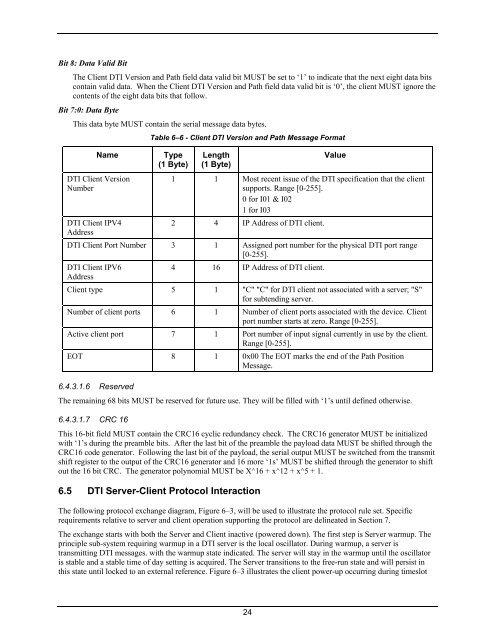
Bit 8: Data Valid BitThe Client DTI Version and Path field data valid bit MUST be set to ‘1’ to indicate that the next eight data bitscontain valid data. When the Client DTI Version and Path field data valid bit is ‘0’, the client MUST ignore thecontents of the eight data bits that follow.Bit 7:0: Data ByteThis data byte MUST contain the serial message data bytes.NameDTI Client VersionNumberDTI Client IPV4AddressTable 6–6 - Client DTI Version and Path Message FormatType(1 Byte)Length(1 Byte)Value1 1 Most recent issue of the DTI specification that the clientsupports. Range [0-255].0 for I01 & I021 for I032 4 IP Address of DTI client.DTI Client Port Number 3 1 Assigned port number for the physical DTI port range[0-255].DTI Client IPV64 16 IP Address of DTI client.AddressClient type 5 1 "C" "C" for DTI client not associated with a server; "S"for subtending server.Number of client ports 6 1 Number of client ports associated with the device. Clientport number starts at zero. Range [0-255].Active client port 7 1 Port number of input signal currently in use by the client.Range [0-255].EOT 8 1 0x00 The EOT marks the end of the Path PositionMessage.6.4.3.1.6 ReservedThe remaining 68 bits MUST be reserved for future use. They will be filled with ‘1’s until defined otherwise.6.4.3.1.7 CRC 16This 16-bit field MUST contain the CRC16 cyclic redundancy check. The CRC16 generator MUST be initializedwith ‘1’s during the preamble bits. After the last bit of the preamble the payload data MUST be shifted through theCRC16 code generator. Following the last bit of the payload, the serial output MUST be switched from the transmitshift register to the output of the CRC16 generator and 16 more ‘1s’ MUST be shifted through the generator to shiftout the 16 bit CRC. The generator polynomial MUST be X^16 + x^12 + x^5 + 1.6.5 DTI Server-Client Protocol InteractionThe following protocol exchange diagram, Figure 6–3, will be used to illustrate the protocol rule set. Specificrequirements relative to server and client operation supporting the protocol are delineated in Section 7.The exchange starts with both the Server and Client inactive (powered down). The first step is Server warmup. Theprinciple sub-system requiring warmup in a DTI server is the local oscillator. During warmup, a server istransmitting DTI messages. with the warmup state indicated. The server will stay in the warmup until the oscillatoris stable and a stable time of day setting is acquired. The Server transitions to the free-run state and will persist inthis state until locked to an external reference. Figure 6–3 illustrates the client power-up occurring during timeslot24