ARKAL Automatic Filters - Netafim
ARKAL Automatic Filters - Netafim
ARKAL Automatic Filters - Netafim

You also want an ePaper? Increase the reach of your titles
YUMPU automatically turns print PDFs into web optimized ePapers that Google loves.
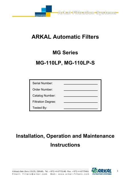
<strong>ARKAL</strong> <strong>Automatic</strong> <strong>Filters</strong>MG Series MG-110LP, MG-110LP-SInstallation, Operation and Maintenance InstructionsDisclaimer:This document and the information enclosed within it contain restricted and/or privileged information that areintended only for usage by authorized Arkal technicians. If you are not a qualified Arkal technician you mustnot take nay action in reliance to this document, unless permitted by Arkal.None of the procedures provided on this file may be used in any form or by any means without permissionfrom Arkal.If you received this file in error please notify Arkal immediately.The confidential nature of and/or privilege in the file enclosed is not waived or lost as a result of a mistake orerror in this file.Arkal accepts no liability whatsoever, whether it was caused by:1. Accessing or other related actions to this file.2. Any links, procedures or materials provided/attached to this file.Arkal assumes that all users understand risks involved within this file and/or its attached materials.All the procedures, drawings, pictures and/or any other information provided in this document are presentedas general information only; they can be altered, removed or changed without any further notice by Arkal.This document does not replace any certified drawing, procedure or information provided by Arkal in referenceto a specific customer, site or project.All rights reserved.2
TABLE OF CONTENTSTECHNICAL SPECIFICATIONS ............................................................................................................................. 4GENERAL ................................................................................................................................................................ 4FLUSH DATA ............................................................................................................................................................ 4CONSTRUCTION MATERIALS ..................................................................................................................................... 4FILTRATION DEGREES AVAILABLE ............................................................................................................................. 4DIMENSIONAL DRAWINGS ................................................................................................................................... 5SAFETY INSTRUCTIONS ....................................................................................................................................... 6GENERAL ................................................................................................................................................................ 6OPERATION, CONTROL AND MAINTENANCE .............................................................................................................. 6USE OF LIFTING EQUIPMENT .................................................................................................................................... 6INTRODUCTION ...................................................................................................................................................... 7GENERAL DESCRIPTION .......................................................................................................................................... 7BASIC FILTER OPERATION ....................................................................................................................................... 7HOW THE SELF-CLEANING CYCLE WORKS ............................................................................................................... 7HOW THE FLUSHING CONTROLLER WORKS .............................................................................................................. 9HOW THE HYDRAULIC RELAY WORKS ...................................................................................................................... 9INSTALLATION ..................................................................................................................................................... 10DESIGN RECOMMENDATIONS ................................................................................................................................. 10PREPARATIONS FOR INSTALLATION ........................................................................................................................ 10INSTALLATION INSTRUCTIONS ................................................................................................................................ 10IMPORTANT! .......................................................................................................................................................... 10FIRST-TIME OPERATION ................................................................................................................................. 11SERVICING ............................................................................................................................................................ 11DRAINING THE FILTER ........................................................................................................................................... 11REMOVING AND INSTALLING THE INLET (COARSE) SCREEN ...................................................................................... 11REPLACING THE PISTON.................................................................................................................................... 12REMOVING AND INSTALLING THE FILTER SCREEN AND THE SUCTION SCANNER ................................ 12MAINTENANCE ..................................................................................................................................................... 13PREPARING THE FILTER FOR LONG-TERM SHUTDOWN OR FREEZING CONDITIONS ................................................... 13PROGRAMMING THE FLUSHING CONTROLLER……………………………………………………… .14PARTS SCHEDULE .............................................................................................................................................. 40PARTS DRAWING #1 ............................................................................................................................................ 41PARTS DRAWING #2 ............................................................................................................................................ 42PARTS DRAWING #3 ............................................................................................................................................ 43PARTS DRAWING #4 ............................................................................................................................................ 443
TECHNICAL SPECIFICATIONSGeneralMaximum flow rate MG-110LP 350m 3 /h; 1542USgpm Consult manufacturer for optimum flow dependingMG-110LP-S 450m 3 /h; 1982USgpmon filtration degree & water quality.Min. Working pressure 2.0bar; 30psi Or lower if pressure is increased for flushingMax. Working pressure10bar; 150psiFilter area12,600cm²; 1,952in²Inlet/Outlet diameter 250mm, 10" Flange standards as per request.Max. Working temperature60 0 C; 140 0 FEmpty weight MG110LP325kg / 717lbEmpty weight MG110LP-S350kg / 770lbFlush dataExhaust valve 40 mm; 11/2" Three flushing valvesFlushing cycle time 45 seconds Depending on the working pressureWasted water per cycle 250liter; 70USgallon at 2bar; 30psiMinimum flow for flushing 30m³/h; 130USgpm at 2bar; 30psiFlush criteriaDifferential pressure of 0.5 bar; 7psi, time and manual operationConstruction materialsFilter housingEpoxy-coated carbon steel 37-2 (St. St. 316 available on request)Filter lid Epoxy-coated carbon steel 37-2Coarse screenReinforced nylonFine screenStainless Steel 316, molded plastic support structureCleaning mechanismPVC and Stainless Steel 316LMotor assemblyReinforced nylon, brass, stainless steelHydraulic pistonStainless Steel 316, brassControl tubingPolyethyleneSealsBUNA-NControlAluminum, Brass, Stainless Steel 316, PVCFiltration degrees availableType Molded screenMicron 500 300 200 130 100 80mm 0.5 0.3 0.2 0.13 0.1 0.084
193 (7.6")193 (7.57")603 (23.7") REF603 (23.7") REF(11.8")300300 (11.8")404 (15.9") REF404 (15.9") REFDIMENSIONAL DRAWINGS777 (30.6") REFINLETOUTLETDRAIN1100 (43.3")2482 (97.7") REF619 (24.3")514 (20.2") REF903 (35.5") REFFigure 1: MG 110LP Filter777 (30.5") REFINLETOUTLETDRAIN1100 (43.3")2680 (105.5") REF767 (30.2")514 (20.2") REF903 (35.5") REFFigure 2: MG 110LP-S Filter5
SAFETY INSTRUCTIONSGeneral Carefully read the installation and operation instructions prior to installation or maintenance. While working with the filter all conventional safety instructions should be observed in order to avoid dangerto the workers, the public or to property in the vicinity. Note that the filter enters into a self-cleaning cycle automatically, without warning. No changes or modifications to the equipment are permitted without written consent provided by themanufacturer or by its representative, on the manufacturer’s behalf.Operation, Control and Maintenance Do not open any cover bolts or fittings unless pressure in the filter has been released. Keep the work area around the filter clean and dry. Always open and close valves gradually. Manual cleaning of the filter element using high water pressure or steam should be performed in accordance with thecleaning system instructions. Manual cleaning of filter element using acid or other chemical agents should be performed in accordance with therelevant material safety instructions.Use of Lifting Equipment While using lifting equipment, make sure that the filter or the lifted part is chained securely and in a safe manner. Avoid working below lifted equipment. Wear a safety helmet while using lifting equipment. Attach the lifting equipment to the lifting eyes only.6
INTRODUCTIONGeneral DescriptionThe MG110 is a sophisticated, yet easy-to-operate automatic filter, with a self-cleaning mechanism driven by a hydraulicturbine. It is designed to work with various types of screens in filtration degrees from 800 to 50 micron, and is available in10" inlet/outlet diameter.The MG110 filter is configured to meet your specific needs according to flow rates and water quality. The filter can beinstalled as a stand-alone unit for low flow rates, or assembled in a group on a manifold when high flow rates and/or alarge screen area are required. The filters are delivered fully assembled, requiring simple connections to the inlet andoutlet, and to the drain.Basic Filter OperationWater enters the filter from the inlet pipe, and passes through a coarse screen, which protects the automatic cleaningmechanism from any large particles or debris. The coarse screen is not cleaned automatically, and should not accumulatelarge quantities of solids. The water then flows through a fine screen which filters out the smaller particles. Water that haspassed through the fine screen is clean and passes into the outlet pipe. Particles of dirt accumulate on the fine screen andform a ―filtration cake,‖ which starts to restrict water flow. As the restriction, or clogging, increases, the pressure in theoutlet pipe becomes lower than in the inlet pipe. When the pressure differential reaches a pre-set value, a self-cleaningcycle is initiated. The self-cleaning cycle takes approximately 45 seconds and does not interrupt the flow of water throughthe filter.How the Self-Cleaning Cycle WorksAt a preset pressure differential (0.5 bar —7 psi), which is detected by a pressure differential switch, the flushing controlleroperates pulse solenoids which allow water to flow to the relay valves, which then activate the hydraulic pistons and opena valve to the rotor chamber (See Figures 2 and 3). The water from the rotor chamber flows out the drain. The pressure inthe rotor chamber drops, releasing a strong flushing stream that flows through the filter.This drop in pressure and corresponding release of the backflush stream create a suction effect at the nozzle inlets. Thiseffect actuates spot cleaning directly in front of the openings of each nozzle at the inner side of the fine screen. The waterand particles passing through the hydraulic rotor cause the suction scanner to rotate, and the piston moves in an axialdirection to the opposite end of the filter.The combination of rotational and axial movement of the suction scanner assembly ensures that the nozzles sweep theentire inner side of the fine screen in a spiral pattern.When the first stroke is completed, the flushing valve closes and after a short interval the flushing controller activates thesecond backflush stroke. The suction scanner assembly spins, moving with the piston in the opposite direction andreturning to its original position.This self-cleaning process takes about 45 seconds, depending on the operating pressure.It is essential that there be at least 2 bar pressure at the inlet to the filter for proper cleaning to take place during flushing.The flushing controller may be operated by pressure differential, manual activation, or by timer.7
Coarse screenFine screenNozzleExhaust valveRotor chamberInletDirt collectorOutletRotorDrainPistonFigure 3: Internal Components of the MG 110Figure 4: Hydraulic Control Line Routing8
How the Flushing Controller WorksThe flushing controller is operated by 12 VDC. It receives a signal from the Differential Pressure Switch when the pressuredifferential reaches the preset value (0.5 Bar, 7 PSI). The flushing controller then sends a 12 VDC pulse to the PulseSolenoid, which provides hydraulic pressure to the Hydraulic Relay which actuates the piston. Where there are severalganged filters, there are solenoids to each relay valve and piston and they are activated in turn, not simultaneously, inorder to maintain inlet pressure and avoid large pressure drops. The unit can also control a downstream valve, which maybe closed while flushing to increase pressure. An optional electronic counter can keep track of the number of flushingcycles.Parameters which may be set include: Mode of operation: Manual, Differential Pressure (DP) only, DP with time override Flushing cycle Flushing time Dwell Time DP response delay time Number of consecutive flushing cycles by DP, to be considered a faultHow the Hydraulic Relay WorksThe hydraulic relay valve, when not actuated by hydraulic pressure from the pulse solenoid, allows pressure to pass to thehydraulic piston, extending it, and holding the suction scanner away from filter lid. When the hydraulic relay is actuated,pressure to the piston is shut off and the water in the piston flows out to the drain. When the piston is no longer underpressure the suction scanner pushes the piston away from the filter lid.FILTER LIDCOMMANDPRESSUREDRAINDRAINPISTONFigure 5: Hydraulic Relay9
INSTALLATIONDesign Recommendations‣ The inlet and outlet pipes must be the same or a larger diameter than the inlet and outlet diameters of the filter.‣ The upstream pressure source should not drop below 30 psi (2 bar) during the rinse cycle. If this cannot be ensured,consult the manufacturer.‣ If a prolonged pipeline fill time causes a temporary high flow and low pressure situation, it recommended that youinstall a pressure sustaining valve downstream of the filter. The pressure sustaining valve will ensure a controlled fillupof the line.‣ If continued water delivery is essential even during ―down time‖ maintenance periods, it recommended that a manualor automatic by-pass be installed, and that isolating valves be installed up and downstream of each filter unit forisolation purposes.‣ Shut off valves must be installed in the inlet and outlet lines to enable maintenance.‣ A non-return valve should be installed where water hammer or back flow may be a problem.‣ The filter must be installed in the direction of flow indicated by the arrow on the filter body.‣ Secure the drain pipe so that there is no movement during flushing.‣ The highest point of the drain pipe should be no more than one half meter above the filter.‣ The drain pipe must allow free flow and be free of restrictions.Preparations for Installation‣ Ensure suitable lighting at the area of the filter to enable good visibility and safe maintenance.‣ Arrange suitable platforms and safety barriers to enable easy, safe access to the filter.‣ Allow a convenient approach and enough space for dismantling and maintenance.Installation Instructions‣ Ensure the direction of flow is according to arrows marked on the filter housing‣ Install a drain valve in place of one of the pipe plugs in the inlet or outlet pipe on the installation manifold.Important!‣ Prevent static back pressure or reverse flow through the filter.‣ Install a manual or a hydraulic valve downstream of the filter.‣ The filter may enter flushing mode automatically, without warning.10
FIRST-TIME OPERATION1. Remove a plastic plug from one of the outlet holes on the top of the filter to bleed air from the filter.2. Open the inlet valve.3. Close the plastic plug when all the air is bled from the filter.4. Make sure the filter is clean and dry.5. Check all fittings and flanges for leaks.6. Open the outlet valve.7. Perform manual flushing, by selecting ―Manual‖ in the flushing controller.8. Check that the inlet pressure does not drop below 2 bar during flushing.The filter is ready for operation. Observe at least one automatic flushing cycle, activated by time or differential pressure.ServicingDraining the Filter1. Close the inlet valve2. Close the outlet valve.3. Open the drain valve to release pressure. To avoid water draining onto the area around the filter, install a drain hoseonto the drain valve.Removing and Installing the Inlet (coarse) Screen1. Drain the filter.2. Remove the filter cover nuts and the cover.3. Remove the inlet screen.4. Before reinstalling the screen, make sure that the fine filter screen is properly seated.5. Push the coarse screen into place.6. The screen must be seated in the base of the fine filter and must be flush with the flange of the filter housing or 1 mm.inside. It should not project outside the flange.7. If the screen does not fit exactly, plastic segments may be removed or added as necessary. The screen is suppliedwith two spare segments stored as in the following figure.8. Place the O-ring into the groove into the cover. It may be necessary to apply silicone grease to hold it in place.9. Close the cover and tighten the nuts evenly in an alternating pattern.10. Activate the filter as in the section "Operating the Filter for the First Time."A thick anda thin sparesegment arestored here.Flush withflange or 1 mminsideFigure 6: Inlet Screen11
Replacing the Piston1. Drain the filter.2. Remove the eight nuts holding the piston and cylinder assembly, and remove the assembly.3. Inspect the suction scanner to make sure it moves freely in its bearings and the end that mates with piston is notdamaged.4. Apply silicon grease to the O-ring at the base of the piston/cylinder assembly.5. Push the piston/cylinder onto the eight studs, taking care that the O-ring slides into the opening and seats properly.6. Place nuts on the studs. Tighten gradually in a criss-cross pattern to avoid binding.7. Activate the filter as in "Operating the Filter for the First Time."Removing and Installing the Filter Screen and the Suction Scanner1. Drain the filter.2. Remove the inlet screen.3. Remove the piston and cylinder assembly.4. Pull out the filter screen and suction scanner as an assembly.5. Insert the filter screen/suction assembly making sure it is seated and is flush with the piston end of the filter housing.6. Make sure that the suction scanner moves freely in its bearings.7. Install the piston and cylinder assembly.8. Activate the filter as in "Operating the Filter for the First Time."Should be seatedand flush with flangesurfaceSuctionscanner mustturn and slidefreelyFigure 7: Filter Screen/Suction Scanner Assembly12
MaintenanceIt is recommended to inspect the filter once a year, in the off season. Remove the filter as described above and inspectthe screen and O-rings, clean as necessary, and lubricate with silicone grease before reassembling.In cases where clogging of the inlet screen occurs, experience with the local conditions will determine how often thescreen should be checked as a routine.Preparing the Filter for Long-Term Shutdown or Freezing Conditions1. Drain the filter.2. Remove the filter screens as described previously and clean and dry them.3. Disconnect the hydraulic lines to drain water out of them and reconnect.4. Push the piston rod inward to remove water from the cylinder.5. Reassemble.13
PROGRAMMING THE FLUSHING CONTROLLERArkal’s Flushing-Controllers product line is a family of electronic devices capable of controlling the flushingprocess of various automatic-filter models. Currently this line consists of three products; one AC controller andtwo DC controllers.This document is the user-manual of the 6 solenoids DC Controller and it describes the configuration processand the operation procedures of the V7 controller version.Note: This picture is for illustration purpose only14
Introduction & How to use this manualArkal’s Flushing-Controllers product line is a family of electronic devices capable of controlling the flushingprocess of various automatic-filter models. Currently this line is consisting of three products; one AC controllerand two DC controllers.This document is the user-manual of the 6 solenoids DC Controller and it describes the configuration processand the operation procedures of the V7 controller version.Before operating the controller please read this manual carefully. Make sure that:You are familiar with the safety instructionsYou know how to use the control’s User-Interface panelThis manual consists of the following chapters:A. General description – The controller’s capabilities, the various configuration options and the types offilters the controller can serve – Page 17.B. Flushing methods – Detailed description of the various flushing sequences possible to operate withthe controller – Page 17.C. The User Interface Panel - How to use the panel – Page 21.D. Entering data - How to modify numbers and parameters – Page 24.E. Configuration – How to configure the controller for a specific filter model – Page 26.F. Flushing program – How to enter a flushing sequence program - Page 28.G. Monitoring – How to monitor the controller operation - Page 30.H. Handling faults – How to identify and reset flushing faults – Page 31.I. Technical data – Connection drawing, I/O data, etc. – Page 32.J. Annex A. – Operating filters that require a Delay Valve15
Safety instructions1. The terminals enclosure lid of the unit must remain closed at all times.2. Only a qualified technician may remove this lid and only when the controller is properly disconnectedfrom its power source.3. Servicing the unit can be done only by Arkal’s qualified technician.4. Make sure that the filters controlled by the controller are disconnected from the water systemwhenever servicing the controller.5. In case the controller is connected to an external AC power supply unit, make sure that the powersupply connection is done properly and complies with your local standards for High Voltage out-doorsconnection.6. No alterations or changes of the unit are allowed.7. Never cut, connect or disconnect any wire at the controller’s vicinity.8. Make sure that the controller is not exposed to water splashes.9. Keep the keyboard transparent-cover closed at all times when not using the keyboard.16
A. General DescriptionArkal’s DC Controller is an electrical/electronic device designed for controlling the flushing process of various types ofautomatic filters.The controller is capable of controlling up to 6 12VDC Latch Solenoids which enables it to operate several types of filtrationsites such as:• <strong>Automatic</strong> screen filters batteries, up to 6 units each.• Gravel media filters batteries, up to 6 units each.• <strong>Automatic</strong> disc filters batteries, up to 6 units each.• One Arkal TAF Electronic Filter.Unlimited number of controllers can be chained together in order to control large filtration sites.The flushing process can be triggered by:• Differential Pressure (DP) signal• Time parameter• Manual Start command• Remote Start signal (By receiving an End of Cycle input from a chained controller)Beside the filters outputs and the DP input the controller is also capable of controlling the following additional functions:• Main Valve (replaces one of the 6 maximum filter units outputs)• Delay Valve (replaces one of the 6 maximum filter units outputs)• Dry Contact Auxiliary Output that works in parallel with the main/delay valves• Alarm output• End of Cycle output• Pause inputThe controller's enclosure is made of Polycarbonate and is designed for outdoor use (IP 65).B. Flushing MethodsThis chapter lists and describes the sequence of operation of the major flushing methods possible to operateusing Arkal Flushing Controller:1. Controlling Arkal TAF Electronic filter:1.1 A single TAF filter:Starting the flushing cycle:• DP signal: Once a signal from the DP switch is received the controller starts to count down the DP delaytime (see screen number 7). If the signal remains present till the end of the count down a flushing cycle starts.• Time parameter: By the end of each flushing cycle the controller starts to count down the Time betweenFlushes Parameter (see screen number 7). Once this parameter is counted down to zero a flushing cycle starts.Please note that if a flushing cycle is started by a different trigger (i.e. DP signal) the controller re-set thecount down of the time between flushes parameter and starts to count it again.• Manual Start: The user initiates a flushing cycle by pressing Enter in the ―For Manual Flush Press ‖screen (see screen number 3).• Remote start signal: Works the same as a regular DP signal.17
2. Controlling a single automatic screen or gravel media filter:2.1 A single screen or gravel media filter:Starting the flushing cycle:• The same as in ―A single TAF filter‖ above.The flushing cycle:• The same as in ―A single TAF filter‖ above.2.2 A single screen or gravel media filter with a Main Valve:Starting the flushing cycle:• The same as in ―A single TAF filter‖ above.The flushing cycle:• The same as in ―TAF filter with downstream valve‖ above.3. Controlling a battery of automatic screen or gravel media filters:A battery of automatic screen or gravel media filters consists of 2-6 filters installed in parallel and serves thesame water system, where one Arkal Flushing Controller controls the system.This arrangement allows a sequential flushing process where only one filter flushes at a time and the filters areflushed one after the other.Please note: The maximal number of filters in a battery controlled by a single controller is 6 where neitherMain Valve nor Delay Valve are configured, 5 where a Main Valve or a Delay Valve is configured and 4 whereboth Main and Delay valves are configured.3.1 A battery of screen or gravel media filters without a Main valve:Starting the flushing cycle:• The same as in ―A single TAF filter‖ above.The flushing cycle:• Solenoid valve number 1 is switched on, the flushing of the first filter of the battery starts and thecontroller starts to count down the Flushing Time parameter (see screen number 5). Once this parameter iscounted down to zero the solenoid of the first filter is switched off and the process moves to the nextstage.• The controller counts down the ―Between <strong>Filters</strong> Delay‖ parameter (see screen number 5) and once thiscount reaches zero the controller switches on the solenoid of the second filter of the battery and startsto count down again the Flushing Time parameter. Once the flushing process of the second filter isfinished the controller counts again the delay between filters and starts the flushing of the next filter.This process continues till the last filter is flushed and the flushing cycle is ended.19
3.2 A battery of screen or gravel media filters with a Main Valve:Starting the flushing cycle:• The same as in ―A single TAF filter‖ above.The flushing cycle:• The Main Valve solenoid is switched on and closes the battery’s Main Valve. The controller countsdown the ―Delay Main Valve Close‖ parameter (see screen number 8). Once this count reaches zero theprocess moves to the next stage.• Solenoid valve number 1 is switched on, the flushing of the first filter of the battery starts and thecontroller starts to count down the Flushing Time parameter (see screen number 5). Once this parameter iscounted down to zero the solenoid of the first filter is switched off and the process moves to the nextstage.• The controller counts down the ―Between <strong>Filters</strong> Delay‖ parameter (see screen number 5) and once thiscount reaches zero the controller switches on the solenoid of the second filter of the battery and startsto count down again the Flushing Time parameter. Once the flushing process of the second filter isfinished the controller counts again the delay between filters and starts the flushing of the next filter.This process continues till the last filter is flushed and its solenoid is switched off, then the processmoves to the next stage.• The controller counts down the ―Delay Main Valve Open‖ parameter (see screen number 8). Once thiscount reaches zero the Main Valve solenoid is switched off causing the Main Valve to reopen and theflushing cycle ends.20
C. The User Interface PanelArkal’s Flushing Controller User Interface Panel consists of:• Display screen - a 2 X 16 characters LCD display. (See picture on the front page of this manual.)• Keyboard – a 5 keys keyboard divided into 4 directional Arrow keys and an Enter key.When the controller’s power supply is switched on the following screen appears:DC CONTROLLER v709/10/07 11:13This is the entry point to a series of 13 main screens that each one of them by itself is an entry point to aspecific function of the controller.Use the Left and the Right Arrow keys to move through these 13 main screens as indicated in the followingillustration.Please note that:• Pressing the Right Arrow Key when the last screen is displayed moves the view point to the first screen.• Pressing the Left Arrow Key when the first screen is displayed moves the view point to the last screen.AC CONTROLLER v918/12/05 00:42Status:B.FlushinTime: 4:23:35For manual flushPress Define controlerPress code - XXXAC CONTROLLER v918/12/05 00:42Status:B.FlushinTime: 4:23:35For manual flushPress Define controlerPress code - XXXAs indicated in the following illustration, in order to operate a specific function move first with the arrow key tothe entry point of that function (on the main 13 screens) and then use the Down Arrow or the Enter key (depends onthe nature of the specific function) to enter to requested function specific screens.Status:B.FlushinTime: 4:23:352AINPUTS OUTPUTS00 00000000Delay main valveClose: 1 Open: 0EnterDelay main valveClose: ? Open: 0EnterDelay main valveClose: 1 Open: ?EnterThe layout drawing of the controller’s screens appears in the following two pages.Please note: At the upper left corner of each screen in the following drawing there is a number. This numberis used to identify the screen in the chapter describing its actual function further down at this manual.21
Amiad's DC Filter Flushing Controller - User Interface Layout (Page #1)1 2 3 4 5 6DC CONTROLLER v7 Status:B.FlushinFor manual flushTimeBet.FlushingFlushTime: 00:20Flu Til Fault: 309/10/07 11:13Time: 4:23:35Press 5:00:00 (D:H:M)Bet.Filt.: 00:10Delay: 102AINPUTS OUTPUTS00 00000000EnterTo stop flushingPress EnterEnterTimeBet.Flushing█:00:00 (D:H:M)EnterEnterFlushTime: ██:20Bet.Filt.: 00:10EnterEnterFlu Til Fault: █Delay: 10EnterTimeBet.Flushing5:██:00 (D:H:M)EnterTimeBet.Flushing5:00:██ (D:H:M)EnterFlushTime: 00:██Bet.Filt.: 00:10EnterFlushTime: 00:20Bet.Filt.: ██:10EnterFlu Til Fault: 3Delay: ██Enter(Appears only on Fault)To Release D.P.Fault FlushTime: 00:20Bet.Filt.: 00:██Enter7 8 9 10 11 12 13Delay: D.P.: 19Delay main valveClose: 1 Open: 0Delay valveOpen: 5 close: 5Flushing counter11Set time18/12/05 03:11Battery6.14 VoltDefine controlerPress code - XXXEnterDelay: D.P.: ██EnterEnterDelay main valveClose: █ Open: 0EnterEnterDelay valveOpen: █ close: 5EnterEnter10AReason: by Manua18/12/05 01:09EnterSet time██/12/05 03:11EnterEnterDefine controlerPress code - ███EnterDelay main valveClose: 1 Open: █EnterDelay valveOpen: 5 close: █EnterFlushing counter██EnterSet time18/██/05 03:11EnterSet time18/12/██ 03:11Continues onnext pageEnterSet time18/12/05 ██:11EnterSet time18/12/05 03:██Enter
Continues frompage #1Amiad's DC Filter Flushing Controller - User Interface Layout (Page #2)See Chapter: How toEnter numbers and parameters14 15 16 17Select languageFilter number: 4Main valve: *yesDP Input: *yes* EnglishDelay valve: *yesDisc filter: *noEnterEnterEnterEnterSelect language█ EnglishFilter number: █Main valve: █yesDelay valve: *yesDP Input: █yesDisc filter: *noEnterEnterSelect language█ EspanolFilter number: 2Main valve: *noDelay valve: █yesDP Input: *noDisc filter: █yesEnterEnterEnterEnter18 19 19INPUTS OUTPUTSTo finish press00 ------00EnterEnterINPUTS OUTPUTS00 █-----00INPUTS OUTPUTS00 0-----00Return topage #1INPUTS OUTPUTS00 0█----00Enter
D. Entering DataWhen the controller is first installed it is necessary to enter and/or adjust its basic parameters. Theseparameters, entered to the controller’s nonvolatile memory through a Configuration Process, enable it toperform the suitable flushing method designed for the type of filters it serves.Once the controller is properly configured a Flushing Program has to be entered. This program defines theparameters according to which the controller performs the actual flushing of the filters.During the Configuration and the Flushing Program Entry procedures the user needs to enter two types of data:1. Parameter selection – Selecting a required parameter from a predefined list in the controller’s memory2. Entering numbers – Supplying the controller with numeric dataThe following paragraph explains the method of entering data to the controller in general. Specific instructionsare given in the Configuration and the Flushing Program paragraphs of this manual.Selecting a parameter:1. Using the Left/Right arrow keys move to the screen that contains the parameter to be selected.Press Enter. This will put a blinking cursor over the asterisk near the first parameter to be selected.EnterMain valve:yesDelay valve: *yes2. Use the Up and Down Arrow keys to scroll through the list of possible options and select the requiredparameter. Then press Enter to store the parameter in the controller’s memory and to move to the nextparameter in the current screen (A). Repeat the selection process with the Up and Down Arrow keys andthen press Enter to return to the entry point screen (B). (Please note that if the screen contains only one parameterpressing Enter after the selection process will return you the entry point screen.)(A)Main valve: █noDelay valve: *yesEnterMain valve: *noDelay valve: █yes24
(B)Main valve: *noDelay valve: █noEnterEntering a Number:Main valve: *noDelay valve: *no1. Using the Left/Right arrow keys move to the screen that contains the number to be changed.2. Press Enter. This will put a blinking cursor over the number to be changed.EnterFlu Til Fault: 3Delay: 103. Entering a Single Digit number: Use the Up and Down Arrow keys to scroll through the 0-9 digits andselect the required number. Then press Enter to store the number in the controller’s memory and tomove to the next parameter in the current screen (A).process (C).(A)Flu Til Fault: 9Delay: 10EnterFlu Til Fault: 9Delay: 104. Entering a Multi Digit number: Once the Enter key is pressed the blinking cursor appears over the rightmostdigit of the number. Press the Right Arrow Key to delete all the digits of the number (B). Use the Upand Down Arrow keys to scroll through the 0-9 digits and select the required one for the left-most digit ofthe number, then press the Left Arrow Key to push this digit to the left. Repeat the process of selectingthe required digit and pushing it to the left till the complete number is set. Press Enter to finish the(B)EnterFlu Til Fault: 9Delay: 10Flu Til Fault: 9Delay:25
(C)Example: Changing the Delay Parameter from 10 to 37:• Press the Right Arrow Key to delete the ―10‖ digits.• Use the Up or the Down Arrow Key to select "3".• Press the Left Arrow Key to push the ―3‖ to the left.• Select "7" by using the Up or the Down Arrow Key.• Press Enter.Setting the Real Time ClockOnce power is first connected to the controller the real time clock needs to be set. This is done at screennumber 11.Number Screen Description11 Set time18/12/05 03:11Navigate to this screen, press Enter and set the controller’s clockaccording to your local time zone and date. Note: do not change theclock setting while flushing.E. ConfigurationAfter the installation of the controller and prior to the first operation it is necessary to perform the configurationprocess in order to synchronize the controller with the filters it be flushed.Start the configuration process by navigating to screen number 13 and entering 123 in the code field.Define controlerPress code - XXX26
Important notes:• Never change the controller’s configuration while flushing.• Once the controller is configured EXIT the configuration process, the controller is notoperational while in configuration mode.The layout of the screens involved in the configuration process can be found on page 11 of this manual. Thefollowing table describes each one of the screens of the configuration process and it contains three columns.• The first column shows the screen number as appears at the upper left corner of the screen drawing inthe layout diagram on page 11 of this manual.• The second column shows the default setting of the screen.• The third column explains the controller-task controlled by this screen.Number Screen Description14Select language* English15 Filter number: 4 Upper line:1617Main valve: *yesDelay valve: *yesDP Input: *yesDisc filter: *noSelect the user interface language of the controller.Currently it is possible to choose English or Spanish.Defines the number of filters (solenoids) controlled by the controller.Upper line:Defines if the controller activates a Main Valve.Lower line:Defines if the controller activates a Delay Valve.Notes:1. See chapter B for a description of the Main Valve operation.2. See Annex A. for a description of the Delay valve operation.3. If only a Main Valve or a Delay Valve is selected the solenoid ofthis valve is assigned to Output Number 6. However if both MainValve and Delay Valve are selected the Delay Valve solenoid isassigned to Output Number 5 and the Main Valve is assigned toOutput Number 6.Upper line:Defines if in addition to the ―start by time‖ the flushing process maystart also by a signal received from a Differential Pressure sensor.Lower line:Defines the type of the controller’s reaction in case where the DPcontinues to signal at the end of the flushing cycle.Note:See chapter H for DP fault description.27
Number Screen Description1819INPUTS OUTPUTS00 ------00To finish pressThis screen helps the technician installing or servicing the controller toverify the status of the controllers I/O.Inputs:Left digit - DP sensor status:• 0= no DP signal• 1= DP signal is presentRight digit – Pause input status:Outputs:• 0=no Pause signal• 1= Pause signal is presentThe first 6 digits from the left show the status of the filters, the mainvalve and the delay valve outputs:• 0= The output is switched off• 1= The output is switched on• - = There is no solenoid connected to this outputDigit number 7 (from left) – Alarm signal:• 0= No Alarm signal (the Alarm output is switched off)• 1= Alarm signal (the Alarm output is switched on)Digit number 8 (from left) – End of Cycle (sequence) signal:• 0= The Sequence signal is off• 1= The Sequence signal is on and being sent to activate theflushing process of another controller.Press Enter to exit the Configuration process and return to the MainScreen (to Screen number 1).Notes:• This is the only exit point of the configuration process,navigate to this screen and press Enter to terminate it.• The controller begins automatic operation only afterexiting the Configuration process!!!F. Flushing programOnce the controller is properly configured and the real time clock is set it is necessary to enter a flushingprogram in order for the actual operation of the controller to start.The layout of the screens involved in the Flushing program entry can be found on page 10 of this manual. Thefollowing table describes each one of the screens of the Flushing program and it contains three columns.28
• The first column shows the screen number as appears at the upper left corner of the screen drawing inthe layout diagram on page 10 of this manual.• The second column shows the default setting of the screen.• The third column explains the controller-task controlled by this screen.Note: Do not change the program while flushing, stop the flushing first.Number Screen Description4 TimeBet.Flushing5:00:00 (D:H:M)56789FlushTime: 00:20Bet.Filt.: 00:10Flu Til Fault: 3Delay: 10Delay: D.P.: 19Delay main valveClose: 1 Open: 0Delay valveOpen: 5 close: 5This screen defines the time between scheduled flushing cycles. Theentry format is Days (0-99), Hours (0-23) and minutes (0-59).Upper line:Defines the flushing time (the duration of flushing) of one filter. Theentry format is Minutes (0-99) and Seconds (0-59).Lower line:Defines the delay time between filters (between the end of one filterflushing and the beginning of the next). The entry format is Minutes (0-XX) and Seconds (0-59).Upper line:Defines the number of maximum flushing cycles till fault; the maximumallowed number of continuous flushing cycles when the DP signalremains continually ON (probably due to a filter clog). If this number isexceeded the controller enters into Fault mode and activates thealarm. The entry format is 0-9.Lower line:Defines the delay between one flushing cycle and the next when thecontroller receives a continuous signal from the DP switch. The entryformat is Seconds (0-99)Defines the time required for the DP signal to remain ON until thecontroller responds by activating the flushing cycle. The entry format isSeconds (0-99).Note: This screen appears only if a main valve is configured and itdefines the main operation as described in chapter B.Close: The time between closing the main valve and activating theflushing cycle.Open:the main valve.The time between deactivating the flushing cycle and openingThe entry format is Seconds (0-99).Note: This screen appears only if a Delay valve is configured and itdefines the Delay valve operation as described in Annex A.The entry format is Seconds (0-99).29
G. MonitoringDuring the regular operation of the controller it is possible to:• Monitor the current status of the controller• Read information on past activities of the system• Perform manual operation and intervene in the flushing process• Read and monitor the voltage of the controllers batteryThe layout of the screens involved in the controller’s Monitoring can be found on page 10 of this manual. Thefollowing table describes each one of the controller’s Monitoring screens and it contains three columns.• The first column shows the screen number as appears at the upper left corner of the screen drawing inthe layout diagram on page 10 of this manual.• The second column shows the default setting of the screen.• The third column explains the controller-task controlled by this screen.Number Screen Description2310Status:B.FlushinTime: 4:23:35For manual flushPress Flushing counter11This screen shows the current status of the controller.The upper line: - shows the current status, The possible messages are:• Flushing (the flushing filter number is also displayed)• Between filters (counting the delay between filters)• Between flushing cycles (counting the time to the next flushing cycle)• Delay (counting the D.P. delay)• Fault (the controller is at D.P. fault)The lower line: - shows the countdown of the time related to the upperline message, for example:• When the controller is between flushing cycles this line shows thetime left to the next flushing cycle.• When filter number 1 is flushing this line shows the time left for thisfilter to flush.In this screen the user can manually start and stop a flushing cycle.• Press Enter to immediately initiate a flushing cycle. Once the cycle isstarted the controller displays the status screen (screen number 2).• Press the right arrow key to return to this screen.• In order to stop the flushing cycle press Enter again, otherwise theflushing cycle will continue till its regular completion.This screen displays the number of flushing cycles performed since thelast time this filed was cleared.• The controller stores a record showing the start time and reason(PD, Time or Manual) for each one of the last 50 flushing cycles. Usethe Up and Down arrow keys to scroll through these records.• Press Enter to edit and clear the flushing counter.30
12Battery6.14 VoltThis screen shows the voltage of the controller’s battery.The minimum operational level is 4.7 VH. Handling faultsArkal’s flushing controller can detect and respond to filter clogs. This is done by monitoring the status of the D.P.signal. The user can configure the controller’s response through the following two screens:Number Screen Description617Flu Til Fault: 3Delay: 10DP Input: *yesDisc filter: *noIf by the end of a flushing cycle the D.P signal remains ON thecontroller counts down the delay entered in this screen (in seconds),and if by the end of this delay the D.P. is still ON a new flushing cyclestarts. In case the D.P. remains permanently ON the delay is countedagain and this process repeats till the ―maximum number of flushingcycles till fault‖ entered at this screen is exceeded.Once this happens the controller enters into a Fault Status asdescribed below this table.Please note that if zero is entered at the ―maximum flushing cycles tillfault‖, the controller never enters to ―D.P. Fault Status‖ and continuesto initiate new flushing cycles constantly whenever the D.P. signalremains ON.If the lower line parameter of this screen is set to ―Disc filter *yes‖ thecontroller immediately enters to ―D.P. Fault Status‖ whenever the D.P.signal remains ON at the end of the first flushing cycle.When the controller enters to D.P. Fault the main status screen (Screen number 2) shows the fault status and time.Status:D.P. FaultTime: 4:23:35A new screen appears to the right of the main status screen (Between screens 2 and 3) displaying the option to resetand release the fault and the controller’s buzzer is activated.To Release D.P.Fault When the controller enters to D.P. Fault check if the filters are clogged and if needed clean them manually.Check the D.P. switch and then cancel the fault by navigating to and pressing Enter in the ―Release FaultScreen‖ which appears between screens 2 and 3.AC CONTROLLER v918/12/05 00:42Status: D.P. FaultTime: 4:23:35To Release D.P.Fault For manual flushPress Define controlerPress code - XXX31
Battery and power levels:In order to prolong the battery life the controller switches off the display screen of the unit once the keyboard isnot used. In such case the operation of the unit continues as usual. Press any key to switch on the displayscreen.The required voltage level for regular operation is 4.7-12 Volts. Once the voltage level drops below 4.7 V thecontroller stops its regular operation, switches on the Alarm and enters into Fault status.I. Technical dataElectrical Connections:The Electrical Connections BoardExternal Power supply6-12 VDC:This connection terminal is used to connect, when available, a 6-12 VDC 500 milliamp external power supplyunit to the controller.Once such external power supply is connected the internal batteries of the controller are used only for a backupand not for the actual operation of the controller.32
Outputs:OUT1-OUT6:These are the terminals for the Two Wire 12V DC Solenoids. If a main valve or a delay valve has beendesignated during the controller’s configuration process, it's solenoid's output will always assigned to OutputNumber 6. For example, if two outputs are defined as filters (OUT1-OUT2), the main valve output will be OUT6.If both main valve and delay valve are defined, Output Number 5 will be the delay valve output and the OutputNumber 6 will be the main valve output.Auxiliary Output (marked on the controller’s terminal strip as Main Valve):This output is opened and closed automatically by the controller in parallel to OUT-6, i.e. this output is activatedwhenever OUT-6 is activated.Alarm:This output is a Dry Contact Relay (a free potential contact); it provides a command pulse to an external alarmdevice. The alarm is activated in two cases:• When a selected number of consecutive flushing cycles have taken place due to continuous differentialpressure input signal, which usually occurs when the filters are clogged.• When the battery voltage is lower than 4.7 VDCEnd of Cycle (End C):This output is a Dry Contact Relay (a free potential contact); at the completion of a flushing cycle it provides acommand pulse connected to the D.P. input of an external controller (slave). This pulse lasts 5 seconds andtakes place after all the other outputs of the flushing process have been activated and de-activated. See―Chaining Arkal Controllers‖ drawing at the end of this chapter.Note: This output in marked as SEO in the AC controller, the functionality is the same and therefore it ispossible to chain AC and DC controllers.Inputs:D.P.:This is the connection to the differential pressure switch.Pause:Connecting these two terminals creates a signal which causes the controller to stop operating until theconnection between these two terminals is disconnected.33
Installing and replacing the batteries:The controller is powered by four D batteries. The unit starts to operate automatically 10 seconds after insertingthe batteries. Alternatively, an external 6-12V DC supply can be connected to the power connection terminal;(Labeled as 6-12 VDC on the terminal board circuit board.)If an external power supply is connected while a set of batteries is installed, the batteries are served as abackup and are not in use as long as the external power supply is connected.In order to install or replace the batteries:• Open the transparent keyboard lid.• Unscrew the 4 screws located in the corners of the keyboard and screen panel.• Remove the panel from the controller housing to get access to the battery compartment.• Insert 4 D type 1.5VDC batteries according to the (+) and (–) marks on the compartment.• Insert the panel and cover the battery compartment.• Re-screw the 4 screws and close the transparent lid.34
I/O Terminal Connections Drawing:35
Chaining Arkal Controllers:In order to operate a battery of screen or gravel media filters that include a larger number of filters than oneArkal’s Flushing Controller can handle, it is possible to chain few controllers for the job.The D.P. switch that reads the pressure drop across the battery is connected to the first controller of the chain(the Master). The SEQ (or End of Cycle) output of the master controller is connected to the D.P. input of thesecond controller of the chain (the first slave) and this controller SEQ output is connected to the D.P. input ofthe nest. This type of connection can be spanned over as many controllers as needed.When the actual D.P. switch send a signal the master controller starts a flushing cycle. Once this cycle iscompleted the master controller sends a signal through its SEQ output to the second controller to start itsflushing cycle, and so on till the last controller in the chain as illustrated in the following drawing.Master ControllerSlave 1 ControllerSlave N ControllerEnterEnterEnterD.PSEQD.PSEQD.PSEQInputOutputInputOutputInputOutputStandard D.P.Switch36
J. Annex A. – Operating filters that require a Delay ValveIn some cases there is a need to control a Delay Valve together with the filtration system, for example ininstallations where a delay Valve is used for sampling the flushing water.Arkal’s Flushing Controller contains two parameters which allow the user to control a filtration system thatrequires a Delay Valve; these are the ―Delay Valve Open‖ and the ―Delay Valve Close‖ parameters (see screennumber 9).Please not that:• Each one of these parameters should be shorter than the ―Flushing Time‖ Parameter.• The addition of the time set for the ―Delay Valve Open‖ parameter with the time set for the ―Delay ValveClose‖ parameter should be shorter than the time set for the ―Flushing time‖ parameter.The following is a step by step description of the controller operation in installations that include a delay valve:1. A single screen or gravel media filter with a Delay valve:Starting the flushing cycle:• The same as in ―A single TAF filter‖ above.The flushing cycle:• Solenoid valve number 1 is switched on and the flushing of the filter starts.• The controller starts to counts down two parameters in parallel: The ―Flushing Time‖ parameter (seescreen number 5) and the ―Delay Valve Open‖ parameter (see screen number 9).• Once the ―Delay Valve Open‖ parameter is counted down to zero the Delay solenoid is switched on.• During the flushing process when the count down of the ―Flushing Time‖ reaches a value which is equalto the ―Delay Valve Close‖ parameter (see screen number 9) the controller switches off the Delay Valvesolenoid.• Once the ―Flushing Time‖ parameter is counted down to zero the solenoid is switched off and theflushing cycle ends.1.1 A single screen or gravel media filter with both Main and Delay valves:Starting the flushing cycle:• The same as in ―A single TAF filter‖ above.The flushing cycle:• The Main Valve solenoid is switched on and closes the filter’s downstream valve. The controller countsdown the ―Delay Main Valve Close‖ parameter (see screen number 8). Once this count reaches zero theprocess moves to the next stage.• Solenoid valve number 1 is switched on and the flushing of the filter starts.37
• The controller starts to counts down two parameters in parallel: The ―Flushing Time‖ parameter (seescreen number 5) and the ―Delay Valve Open‖ parameter (see screen number 9).• Once the ―Delay Valve Open‖ parameter is counted down to zero the Delay solenoid is switched on.• During the flushing process when the count down of the ―Flushing Time‖ reaches a value which is equalto the ―Delay Valve Close‖ parameter (see screen number 9) the controller switches off the Delay Valvesolenoid.• Once the ―Flushing Time‖ parameter is counted down to zero the filter solenoid is switched off and theprocess moves to the next stage.• The controller counts down the ―Delay Main Valve Open‖ parameter (see screen number 8). Once this countreaches zero the Main Valve solenoid is switched off causing the downstream valve to reopen and theflushing cycle ends.2. A battery of screen or gravel media filters with a Delay Valve:Starting the flushing cycle:• The same as in ―A single TAF filter‖ above.The flushing cycle:• Solenoid valve number 1 is switched on and the flushing of the first filter of the battery starts.• The controller starts to counts down two parameters in parallel: The ―Flushing Time‖ parameter (seescreen number 5) and the ―Delay Valve Open‖ parameter (see screen number 9).• Once the ―Delay Valve Open‖ parameter is counted down to zero the Delay solenoid is switched on.• Once the Flushing Time parameter is counted down to zero the solenoid of the first filter is switched offand the process moves to the next stage.• The controller counts down the ―Between <strong>Filters</strong> Delay‖ parameter (see screen number 5) and once thiscount reaches zero the controller switches on the solenoid of the second filter of the battery and startsto count down again the Flushing Time parameter. Once the flushing process of the second filter isfinished the controller counts again the delay between filters and starts the flushing of the next filter.This process continues till the last filter starts to flush, then the process moves to the next stage.• During the flushing process of the last filter of the battery and when the count down of the ―FlushingTime‖ reaches a value which is equal to the ―Delay Valve Close‖ parameter (see screen number 9) thecontroller switches off the Delay Valve solenoid.• Once the ―Flushing Time‖ parameter of the last filter is counted down to zero the filter solenoid isswitched off and the flushing cycle ends.2.1 A battery of screen or gravel media filters with both Main and Delay valves:Starting the flushing cycle:• The same as in ―A single TAF filter‖ above.38
The flushing cycle:• The Main Valve solenoid is switched on and closes the battery’s Main Valve. The controller countsdown the ―Delay Main Valve Close‖ parameter (see screen number 8). Once this count reaches zero theprocess moves to the next stage.• Solenoid valve number 1 is switched on and the flushing of the first filter of the battery starts.• The controller starts to counts down two parameters in parallel: The ―Flushing Time‖ parameter (seescreen number 5) and the ―Delay Valve Open‖ parameter (see screen number 9).• Once the ―Delay Valve Open‖ parameter is counted down to zero the Delay solenoid is switched on.• Once the Flushing Time parameter is counted down to zero the solenoid of the first filter is switched offand the process moves to the next stage.• The controller counts down the ―Between <strong>Filters</strong> Delay‖ parameter (see screen number 5) and once thiscount reaches zero the controller switches on the solenoid of the second filter of the battery and startsto count down again the Flushing Time parameter. Once the flushing process of the second filter isfinished the controller counts again the delay between filters and starts the flushing of the next filter.This process continues till the last filter starts to flush, then the process moves to the next stage.• During the flushing process of the last filter of the battery and when the count down of the ―FlushingTime‖ reaches a value which is equal to the ―Delay Valve Close‖ parameter (see screen number 9) thecontroller switches off the Delay Valve solenoid.• Once the ―Flushing Time‖ parameter of the last filter is counted down to zero the filter solenoid isswitched off and the process moves to the next stage• The controller counts down the ―Delay Main Valve Open‖ parameter (see screen number 8). Once this countreaches zero the Main Valve solenoid is switched off causing the Main Valve to reopen and the flushingcycle ends.39
PARTS SCHEDULENo. Description Cat. No.1 Filter housing (2 x 10⁶XLP) 15-1100-9222Filter housing (2 x 10⁸LP) 15-1105-62221.1 Plastic plug 1" 83-9810-0100-30001.2 L-Connector 3/8" X 12 82-11-7469-52061.3 L-Connector 1/4" X 6 82-11-7469-46041.4 Arkal Controller 6 DC 84-87-45-00071.4.1 PD switch UE 24-011 84-34-10-00021.4.2 Solenoid 12VDC "NO" (S985) 82-21-2012-00021.4.3 St.St. Nut M6 85-2212-06-0001.4.4 St.St. Washer M6 85-2312-06-0001.4.5 St.St. Bolt M6 X 20 85-2112-06-0201.5 Stud bolt 1/2" X 50 (X8) 85-2431-08-0501.6 Plastic plug 3/4" 83-9810-0075-30002 Fine screen 106XLP 15-1603-xxxxFine screen 108LP15-1803-xxxx2.1 O-Ring 647 81-41-4001-06742.2 Handle bolt 106 LP/XLP 8521-2101-008Handle bolt 108LP 8541-2101-0082.3 Handle 106 LP/XLP 61-5510-0152Handle 108LP 61-5510-01542.4 Spacer disc 65-3903-01232.5 Fine screen bearing 65-3003-02043 Dirt collector ass. 106XLP/108LP 15-1004-50463.1 O-Ring 647 81-41-4001-06743.2 Rotor assembly 55-1006-00113.2.1 Rotor 55-5510-00233.2.2 Rotor adaptor 51-5510-00153.2.3 Rotor bearing housing 65-1024-00263.2.4 Lower Bearing 65-1004-06013.3 F. chamber flat screen 15-1070-0506F. chamber ZZ screen 15-1070-05083.4 Dirt collector 106XLP/108LP 15-1004-00163.4.1 Bolt 3/8" X 8 85-4125-08-0093.4.2 Dirt collector pipe 106XLP/108LP 65-1064-05473.4.3 Nozzle assembly 55-1024-03573.4.4 Collector connecting bolt 65-3044-04513.4.5 Support bolt 51-5510-00103.4.6 Dirt collector shaft 65-3044-01103.4.7 Dirt collector top plug 51-5510-0024No. Description Cat. No.4 Piston lid assembly (CI) 15-1070-05914.1 Piston lid 55-1070-10934.2 Plastic plug 1/4" 82-11-0121-04004.3 L-Connector 1/4" X 6 82-11-6469-46044.4 Piston shaft 65-1005-05224.5 Exhaust valve seat 65-1006-05054.6 Disc seal seat 65-1006-05034.7 O-Ring P2-009 81-41-4000-00094.8 Rod 65-1006-05024.9 O-Ring P2-009 81-41-4000-00094.10 Exhaust valve seat 65-1006-05914.11 O-Ring P2-351 81-41-4000-03514.12 Locking ring 65-1006-05924.13 Disc seal seat 65-1006-05034.14 Bearing 55-1006-05044.15 St.St. Nut 1/4" 85-2211-04-0004.16 O-Ring P-237 81-41-4000-02374.17 U-Ring 95X75X10 81-41-4561-05304.18 Seal holder 65-1006-05394.19 U-Ring 95X75X10 81-41-4561-05304.20 St.St. Cylinder 65-1006-05274.21 Piston rod tie 65-1005-05934.22 O-Ring P-237 81-41-4000-02374.23 Piston lid 65-5510-00064.24 St.St. Lock nut 1/4" 85-2231-04-0004.25 St.St. Washer M6 85-2312-06-0004.26 Plastic plug 1/4" 82-11-0121-04005 Coarse screen 106XLP 15-3002-0003Coarse screen 108LP 15-3002-00016 Flat Filter lid 55-1070-10917 O-Ring P2-448 81-41-4000-04488 Nut 1/2" 85-1211-08-0009 Washer M12 85-1312-12-00010 Hydraulic relay 25-300 15-1009-003210.1 L-Connector 3/8" X 8 82-11-7469-520410.2 L-Connector 3/8" X 12 82-11-7469-520610.3 Connector 1/8" X 6 82-11-7468-460211 Nipple 11/2" NPT 83-2920-0151-0105Nipple 11/2" BSP 83-2920-0150-010540
PARTS DRAWING #141
PARTS DRAWING #242
PARTS DRAWING #343
PARTS DRAWING #444