
You also want an ePaper? Increase the reach of your titles
YUMPU automatically turns print PDFs into web optimized ePapers that Google loves.
<strong>ARKAL</strong> <strong>Automatic</strong> <strong>Filters</strong>M100-6800E SeriesModels: M104XLP, M106XLP, M108LP, M110PElectronically-ControlledSerial Number:Order Number:Catalog Number:Filtration Degree:Tested By:Installation, Operation and MaintenanceInstructions
Arkal <strong>Automatic</strong> <strong>Filters</strong>M100-6800E SeriesModels: M104XLP, M106XLP, M108LP, M110P Electronically-ControlledThis document is the user-manual of the M100 Electronic Controller Series and it describes the installation, theoperation and the maintenance procedures of the filters.Disclaimer:This document and the information enclosed within it contain restricted and/or privileged information that are intended only for usage byauthorized Arkal technicians. If you are not a qualified Arkal technician you must not take nay action in reliance to this document, unlesspermitted by Arkal.None of the procedures provided on this file may be used in any form or by any means without permission from Arkal.If you received this file in error please notify Arkal immediately.The confidential nature of and/or privilege in the file enclosed is not waived or lost as a result of a mistake or error in this file.Arkal accepts no liability whatsoever, whether it was caused by:1. Accessing or other related actions to this file.2. Any links, procedures or materials provided/attached to this file.Arkal assumes that all users understand risks involved within this file and/or its attached materials.All the procedures, drawings, pictures and/or any other information provided in this document are presented as general information only; theycan be altered, removed or changed without any further notice by Arkal.This document does not replace any certified drawing, procedure or information provided by Arkal in reference to a specific customer, site orproject.All rights reserved.
TABLE OF CONTENTSTechnical Specifications ............................................................................................................................... 4Safety Instructions ........................................................................................................................................... 5Dimensional Drawings ................................................................................................................................... 6Self-Cleaning Cycle ......................................................................................................................................... 8Installation ........................................................................................................................................................... 9Preparations ..................................................................................................................................................... 10Getting Started ................................................................................................................................................ 10Troubleshooting.............................................................................................................................................. 11Maintenance...................................................................................................................................................... 12Servicing ............................................................................................................................................................ 13Parts List ............................................................................................................................................................ 19Parts Drawing #1............................................................................................................................................. 20Parts Drawing #2............................................................................................................................................. 21Parts Drawing #3............................................................................................................................................. 22Parts Drawing #4............................................................................................................................................. 23Hydraulic Connections ................................................................................................................................ 24Arkal Electronic Controller ......................................................................................................................... 24
Technical SpecificationsConsult the manufacturer for optimum flow depending on filtration degree & water quality.GeneralMaximum flow rate 400m 3 /h; 1760USgpm Consult manufacturer for optimum flowdepending on filtration degree & waterquality.Min. working pressure2.5bar; 38psiMax. working pressure10bar; 150psiFilter area Flat screen 4600cm²; 713in²Molded screen 6800cm²; 1054in²Inlet/Outlet diameter 100,150,200,250Flange standards as per request.4", 6", 8", 10"Max. working temperature60C; 140FEmpty / Full weight – M104XLP 110kg / 214kg; 245lb / 475lbEmpty / Full weight – M106XLP 120kg / 230kg; 265lb / 510lbEmpty / Full weight – M108LP 140kg / 320kg; 310lb / 710lbEmpty / Full weight – M110P 158kg / 351kg; 350lb / 780lbFlush dataExhaust valve 40 mm; 11/2"Flushing cycle time 15 seconds Depending on the working pressureWasted water per cycle 125liter; 35USgallon at 2bar; 30psiMinimum flow for flushing 30m³/h; 130USgpm at 2bar; 30psiFlush criteriaDifferential pressure of 0.5 bar; 7psi, time and manual operationConstruction materialsFilter housingFilter lidCoarse screenFine screenCleaning mechanismMotor assemblyHydraulic pistonControl tubingSealsControlPolyester coated carbon steel 37-2 (St. St. 316 available on request)Reinforced nylonStainless Steel 316, molded plastic support structurePVC and Stainless Steel 316LReinforced nylon, brass, stainless steelStainless Steel 316, brassPolyethyleneBUNA-NAluminum, Brass, Stainless Steel 316, PVCFiltration degrees availableType Molded screen Flat screenmicron 500 300 200 130 100 80 800 400 200 150 130 100 80 50mm 0.5 0.3 0.2 0.13 0.1 0.08 0.8 0.4 0.2 0.15 0.13 0.1 0.08 0.05
Safety InstructionsGeneral‣ Prior to installation or any treatment given to the filter, read carefully the installation and operation instructions.‣ While treating the filter, all conventional safety instructions should be observed in order to avoid danger to the workers, thepublic or to property in the vicinity.‣ Please note: The filter enters into a flushing mode automatically, without prior warning.‣ No changes or modification to the equipment are permitted without a written notification given by the manufacturer or by itsrepresentative, on the manufacturer behalf.Installation‣ Install the filter according to the installation instructions detailed in this manual.‣ Make sure to leave enough clearance so as to enable easy access for future treatments and safe maintenance operations.‣ Electric wiring should be performed by an authorized electrician only, using standardized and approved components.‣ Install main power cut-off switch close to the control panel.‣ If the control panel is installed far away and there is no eye contact with the filter, a power disconnect cut-off switch shouldbe installed near each filter unit.‣ Installation of the filter should be performed so as to avoid direct water splashing on the electrical components or on thecontrol panel.‣ Extra safety devices should be installed on hot water applications to avoid skin burn danger.Operation, Control and Maintenance‣ Disconnect the filter from power supply before maintenance or treatment.‣ Loosening or unscrewing bolts should be done only after the pressure in the filter had been released.‣ Avoid splashing and water leaking so as to minimize slipping, electrifying or damaging the equipment, caused bymoisture.‣ Always open and close valves slowly and gradually.‣ Remove grease and fat material residues in order to avoid slipping.‣ After treatment has been completed, re-assemble the protection covers of the drive mechanism.‣ Manual cleaning of filter element using high water pressure or steam should be performed in accordance with thecleaning system instructions and without endangering the operator or his vicinity.‣ Manual cleaning of filter element using acid or other chemical agents should be performed in accordance with the relevantmaterial safety instructions and without endangering the operator or his vicinity.Use of Lifting Equipment‣ While using lifting equipment, make sure that the filter or the lifted part is chained securely and ina safe manner.‣ Do not leave lifted equipment if there is no necessity. Avoid working below lifted equipment.‣ Wear a safety helmet while using lifting equipment.Notes‣ The user should arrange suitable lighting at the area of the filter to enable good visibility and safe maintenance.‣ The user should arrange suitable platforms and safety barriers to enable easy access to the filter without climbing onpipes and other equipment.‣ Check and re-tighten all bolts after the first week of operation.
Dimensional DrawingsFilter type: M104XLPFilter type: M106XLP
Filter type: M108LPFilter type: M110LP
Self-Cleaning CycleThe automatic flushing cycle described below takes a few seconds and does not interrupt the supply of process water.Water flows from the inlet through the coarse and fine screens to the outlet. At a pre-set pressure differential (0.5 bar - 7 psi),the controller activates the piston and opens the flushing valve. The water from the rotor chamber flows out the drain. Thepressure in the rotor chamber drops, releasing a strong flushing stream that flows through the filter.This drop in pressure and corresponding release of the back flush stream create suction at the nozzle tips. This effectactuates spot cleaning directly in front of the openings of each nozzle on the inner surface of the fine screen. The water andparticles passing through the hydraulic rotor cause the dirt collector to rotate, and the piston moves in an axial direction to theopposite end of the filter.The combination of rotational and axial movement of the dirt collector assembly ensures that the nozzles sweep the entireinner surface of the fine screen.When the first stroke is completed, the flushing valve closes and after a very short interval the controller activates the secondback flush stroke. The dirt collector assembly spins, moving with the piston in the opposite direction and returning to itsoriginal position.This self-cleaning process takes between 8–15 seconds, depending on the operating pressure.
InstallationRead these instructions carefully before installing and operating the filter.Design Recommendations‣ If a prolonged pipeline fill time causes a temporary high flow and low pressure situation, it is recommended that you installa pressure sustaining valve downstream of the filter. The pressure-sustaining valve will ensure a controlled fill-up of theline.‣ The upstream pressure source should not drop below 30 psi (2 bar) during the rinse cycle. If this cannot be ensured,consult the manufacturer.‣ If continued water delivery is essential even during ―down time‖ maintenance periods, it is recommended that a manual orautomatic by-pass be installed, and that isolating valves be installed up and downstream of each filter unit for isolationpurposes.‣ Avoid placing the drainage pipe on a rising slope to minimize backpressure.‣ Secure the open end of the drain pipe to prevent movement during the rinse cycle.‣ It is recommended to install a mechanical non-return valve downstream of the filter to prevent backflow damage to thescreen.‣ It is recommended to install a pressure gauge on the three-way valve.‣ Check that there is sufficient space to remove the cover assembly and the screen from the filter for troubleshooting.Preparations for Installation‣ Ensure suitable lighting at the area of the filter to enable good visibility and safe maintenance.‣ Arrange suitable platforms and safety barriers to enable easy, safe access to the filter.‣ Allow a convenient approach and enough space for dismantling and maintenance.Installation ProcedureEnsure the direction of flow is according to the arrows marked on the filter housing.1. Connect a minimum of 3" (75 mm) pipe to the exhaust valve. The exhaust pipe should be designed so that it createsminimal resistance to flow of 20m3/h (88 US-gpm). Water should be allowed to flow to atmosphere freely from theexhaust pipe.2. Connect a minimum of 1" (25 mm) flexible tube to the rinse controller drain port. Ensure this drain line is open toatmosphere.IMPORTANT!!‣ Prevent static back pressure or reverse flow through the filter.‣ Install a manual or a hydraulic valve downstream of the filter.NOTE: The filter may enter flushing mode automatically, without prior warning.
PreparationsBefore using the filter for the first time, go through the following check-list carefully. No special training is requiredto carry out these activities.‣ Check that the upstream pressure at the filter inlet is more than 2 bar (30 psi) during the rinse cycle.‣ Check that the filter is mounted in the correct flow direction.‣ Check that all the control tubes are connected properly and that all connections are tight.‣ The nominal diameter of the drainpipe should be at least 3" (75mm).‣ If the recommended upstream and downstream isolation valves have been installed, check that they are shut.Getting StartedFirst operation of filterAfter completing the preparation check-list above, perform the following steps:1. Slowly open the isolating valve at the filter inlet. Water will flow into the filter.2. Check for leaks and repair if necessary.3. Check that the minimum inlet pressure remains 2bar (30psi) or higher.4. Slowly open the isolating valve at the outlet of the filter.5. If there is a by-pass valve, close it slowly.6. Ensure the flow through the filter does not exceed the filter's published maximum flow rate.7. Start a manual flush by pressing the push button on the controller panel.8. During the self-cleaning cycle, check the pressure at the filter inlet and in the rotor chamber.NOTE: The minimum pressure in the rotor chamber should be 1.5bar (22psi) lower than the inlet pressure.
TroubleshootingProblem Possible Cause SolutionThe filter does not flush Valves are closed Open valvesPressure differential is not correctPerform a manual flush as follows:Excessive pressure in therotor chamberInsufficient inlet pressure(less than 2 bar—30 psi)Pressure differentialexceeds 0.7 bar (10 psi)during normal operationWater does not flowthrough the filterDrain pipes are not clearInlet valves not fully openCoarse filter is blockedInlet lines blockedIsolating valves are closed1. Close the filter outlet valve2. Check that the filter outlet and inletpressures are equal3. Perform a manual flush as in item 7, page9.4. Check the pressures at the inlet valve andin the rotor chamberCheck if drain lines are clear. If necessary replacewith a larger (diameter) flush drain line, or shortenthe existing lines.Open inlet valves to maximum.Increase the inlet pressure or throttle the outlet toincrease pressure during the flush cycle.Check coarse filterCheck inlet linesOpen isolating valvesController malfunction See Controller instructions on pages 18-20
MaintenanceNOTE: Depressurize the filter before maintenance (close inlet, and then outlet valve).Checking the Filter1. Remove the filter lid by unscrewing the fastening nuts.2. Extract the coarse screen and clean if necessary.3. Extract the fine screen and clean if necessary. Cleaning may be performed by hosing the screen fromoutside-in, and/or with a nylon brush.4. Check the O-rings of the fine screen and apply grease, if necessary.5. Reassemble the fine screen and the coarse screen.NOTE: Check that the dirt collector shaft is properly aligned in the bearing.6. Return the filter lid and fasten the nuts.7. Perform First Operation of Filter as on page 10.WinterizationFilter operations should be suspended in climates where the filter is exposed to freezing temperatures.1. Check that the outlet isolating valve is closed and perform two manual rinses.2. Close the inlet valve to the filter and release the pressure.3. Remove all drain lines from the valves and rinse controller. These should be drained of water and reconnected.4. Remove the following items from the filter and store in a dry place:‣ Top cover assembly‣ Coarse and fine screen assembly5. Apply grease to the O-rings of the fine screen before storing.At the beginning of the operation season, reassemble the filter elements and check Preparations (on page 10)and First Operation of Filter (page 10).
ServicingDraining the Filter1. Close the filter’s upstream (inlet) valve.2. Close the filter’s downstream (outlet) valve and isolate the filter from the water system.3. Use the manual start function of the electronic flushing controller and start a flushing cycle to release the pressure ofthe filter housing.Removing the Screen and the Dirt Collector1. Drain the filter as described above.2. Remove the filter cover nuts and the cover. Note: Attempting to remove the screen from the piston-side of thefilter will cause damage to the system.3. Pull the coarse screen out of the filter housing.
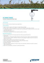
4. Pull the fine screen out of the filter housing. If it is difficult to release the screens use Arkal’s Push Pull Tool (CatalogNumber 15-3000-0011) to extract the screen by performing the following procedure:A. Assemble the tool by inserting the fork shape part into the lever handle.B. Insert the fork shape part over the dirt collector shaft.C. Turn the tool clockwise till the fork teeth catch the fine screen handle.D. Lay the tip of the tool’s lever handle on one of the filter’s housing cover bolts (in order not to damage thefilter paint coating) and secure the joint pin.E. Pull the handle firmly to release the screen.F. Pull the screen out of the filter housing.Joint PinLever HandleFork ShapeA
BCED
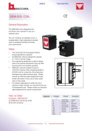
F5. Depending on the actual diameter of your filter use two units of Arkal’s Screen Separation Tool (Catalog Number 65-9999-0203 for 2‖-8‖, 65-9999-0204 for 10‖-12‖ or 65-9999-0205 for 14‖-16‖ filters) to separate the Chamber FlatScreen and the Dirt Collector from the Fine Screen.
Re-installing the Screen and the Dirt Collector1. Insert the Dirt Collector to the Fine Screen. Make sure that the first suction nozzle of the Dirt Collector (A) is pointingdownwards when inserted into the Fine Screen.A2. Use the two Arkal’s Screen Separation Tools to reconnect the Chamber Flat Screen and the Fine Screen.3. Insert the fine screen back to the filter housing (A). Use the fork part of the Push Pull Tool to lift the screen and push itthrough the last few centimeters till it is correctly seated in the filter housing (B).A
B4. Insert the Coarse Screen back to the filter housing (A), install the filter’s cover (B) and re-tighten the cover bolts nuts (c).A B C
Parts ListNo. Description Cat. No.1 Filter housing 104XLP 15-1040-82XXFilter housing 106XLP15-1060-82XXFilter housing 108LP15-1080-62XXFilter housing 110P15-1100-22XX1.1 Plastic plug 1" 83-9810-0100-30001.2 L-Connector 3/8" X 12 82-11-7469-52061.3 Plastic plug 1/4" 82-11-0121-04001.4 L-Connector 1/4" X 6 82-11-6469-46041.5 Arkal 6 DC controller 84-87-45-0007Arkal 6 AC controller 220V 82-81-6004-0207Arkal 6 AC controller 110V 82-81-6004-01071.5.1 PD switch UE 24-011 84-34-10-00021.5.2 Solenoid 24 VAC "NC" 50 Hz 82-21-3024-0954Solenoid 24 VAC "NC" 60 Hz 82-21-3024-0955Solenoid 12 VDC 82-21-2012-00021.6 Stud bolt 1/2" X 50 (X16) 85-2431-08-0502 Fine screen 104/106XLP 15-1603-XXXXFine screen 108LP/110P15-1803-XXXX2.1 O-Ring 647 81-41-4001-06742.2 Handle bolt 104-106 LP/XLP 85-21-2101-008Handle bolt 108LP/110P 85-41-2101-0082.3 Handle 104-106 LP/XLP 61-5510-0152Handle 108LP/110P 61-5510-01542.4 Spacer disc 65-3903-01232.5 Fine screen bearing 65-3003-02043 Dirt collector assembly 15-1004-10463.1 O-Ring 647 81-41-4001-06743.2 Rotor assembly 55-1006-00113.2.1 Rotor 55-5510-00233.2.2 Rotor adaptor 51-5510-00153.2.3 Rotor bearing housing 65-1024-00263.2.4 Lower Bearing 65-1004-06013.3 F. chamber flat screen 15-1070-0506F. chamber ZZ screen 15-1070-05083.4 Dirt collector 15-1004-00163.4.1 Bolt 3/8" X 8 85-4125-08-0093.4.2 Dirt collector pipe 65-1064-05473.4.3 Nozzle assembly 55-1024-03573.4.4 Collector connecting bolt 65-3044-04513.4.5 Support bolt 51-5510-00103.4.6 Dirt collector shaft 65-3044-0110No. Description Cat. No.3.4.7 Dirt collector top plug 51-5510-00244 Piston lid assembly (CI) 15-1070-05914.1 Piston lid 55-1070-10934.2 Plastic plug 1/4" 82-11-0121-04004.3 L-Connector 1/4" X 6 82-11-6469-46044.4 Piston shaft 65-1005-05224.5 Exhaust valve seat 65-1006-05054.6 Disc seal seat 65-1006-05034.7 O-Ring P2-009 81-41-4000-00094.8 Rod 65-1006-05024.9 O-Ring P2-009 81-41-4000-00094.10 Exhaust valve seat 65-1006-05914.11 O-Ring P2-351 81-41-4000-03514.12 Locking ring 65-1006-05924.13 Disc seal seat 65-1006-05034.14 Bearing 55-1006-05044.15 St.St. Nut 1/4" 85-2211-04-0004.16 O-Ring P-237 81-41-4000-02374.17 U-Ring 95X75X10 81-41-4561-05304.18 Seal holder 65-1006-05394.19 U-Ring 95X75X10 81-41-4561-05304.20 St.St. Cylinder 65-1006-05274.21 Piston rod tie 65-1005-05934.22 O-Ring P-237 81-41-4000-02374.23 Piston lid 65-5510-00064.24 St.St. Lock nut 1/4" 85-2231-04-0004.25 St.St. Washer M6 85-2312-06-0004.26 Plastic plug 1/4" 82-11-0121-04005 Coarse screen 104/106XLP 15-3002-0003Coarse screen 108/110 15-3002-00016 Filter lid 55-1070-10917 Lid seal 81-41-4000-04488 Nut 1/2" (X 16) 85-1312-12-0009 Washer 1/2" (X 16) 85-1312-12-00011 Nipple 11/2" NPT 83-2920-0151-0105Nipple 11/2" BSP 83-2920-0150-010512 Hydraulic relay 25-300 15-1009-003212.1 L-Connector 3/8" X 8 82-11-7469-520412.2 L-Connector 3/8" X 12 82-11-7469-520612.3 Connector 1/8" X 6 82-11-7468-4602
Parts Drawing #1
Parts Drawing #2
Parts Drawing #3
Parts Drawing #4
Hydraulic ConnectionsArkal Electronic ControllerArkal’s Flushing-Controllers product line is a family of electronic devices capable of controlling the flushingprocess of various automatic-filter models. Currently this line consists of three products; one AC controller andtwo DC controllers. Please consult the user manual of the controller supplied with your filter for operationinstructions.