Venturi Injector
Venturi Injector
Venturi Injector

Create successful ePaper yourself
Turn your PDF publications into a flip-book with our unique Google optimized e-Paper software.
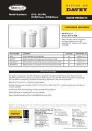
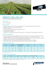
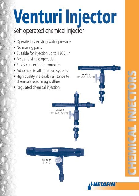
<strong>Venturi</strong> <strong>Injector</strong>Self operated chemical injector• Operated by existing water pressure• No moving parts• Suitable for injection up to 1800 l/h• Fast and simple operation• Easily connected to computer• Adaptable to all irrigation systems• High quality materials resistance tochemicals used in agriculture• Regulated chemical injectionModel F(3⁄4" x 0.9) • (3⁄4" x 0.5)Model A(3⁄4" x 0.9) • (3⁄4" x 0.5)Model D(2" x 12)
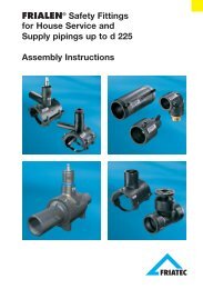
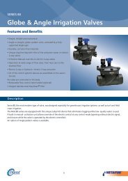
PRINCIPLE OF OPERATIONOperates on the principles of vacuum suctioncreated by an advanced <strong>Venturi</strong> complex. Thisimplements the latest know-how in hydraulictechnology and allows the injectors to operateat small pressure differentials.A vacuum is created as the water flows througha converging passage that gradually widens (seediagram).Injection is activated when there is a pressuredifferential between the water entering theinjectors and the water, and chemical leaving tothe irrigation system.This pressure differential is between 5-75%according to the required injection rate.flow directionchemical suction areachemical inletflow directionINSTALLATIONu Installation of injector as a bypass to a filter andpressure regulatormainsv Installation of injector with booster pumpminimum 1mcheck valvescreen filtercheck valveinjectionpointwater inletto by passboosterpumpchemicalcontainerchemicalinjectorregulatorwater outletinjection pointwater inletchemicalinjectorchemicalcontainerThis method is used when the pressure regulatorbreaks less than the minimum required pressuredifferential and additional desired pressure dropis provided by a filter. This installation utilizesthe combined pressure drop of the filter andpressure regulator to operate the injector and isparticulary suitable for drip irrigation system.This method is used when there is inadequateor undesirable pressure drop in the mains toactivate the injetor. The booster pump createsadditional pressure to activate the injector andprevent head loss to the system. There should bea check valve before the bypass.SPECIFICATIONS REQUIRED FOR ORDERING CHEMICAL INJECTORS• Minimum and maximum flow rate• Permitted or required head loss• Pressure at entry point of irrigation• Flow rate of chemical to be injected into the system
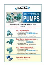
INSTALLATIONw Installation of injector as a bypass to a throttle manual valvethrottle valve(manual)x Installation of injector as a bypass to pressure regulatorwater inletto by passpressure regulatorwater inletto by passwater outletinjection pointchemicalinjectorchemicalinjectorchemicalcontainerThis method is based on a 30% pressure dropusing the manual valve. Care should be taken toensure that the output pressure is sufficient tooperate the irrigation system.chemicalcontainerThis method is based upon a sufficient pressuredrop by the regulator without additional valves.y Installation of injector as a bypass to an existing water pumpwater pumpz Installation of injector in line to the mainschemicalinjectorwater outletcheck valvewater inletchemicalinjectorwater outletinjection pointwater inletinjectionpointchemicalcontainerchemicalcontainerThis method utilizes existing pressure differentialsand saves additional energy.This method is used in cases where the flow ratein the system is low or if pressure reduction is nota problem.Model A&F (3⁄4") D (2” x 12)MaterialsConnectionsDimensionsBody H.G. polypropylene copolymer Plastic with fiberglass fillInternal pieces Chemical resistant plastic Chemical resistant plasticDiameter 3⁄4" male 2”Thread type Male NPT, BSP Female NPT, BSPHeight (mm) 352 380Length (mm) 290 520
PERFORMANCE DATAOPERATING MODEL A/F MODEL A/F MODEL DPRESSURE 3⁄4" x 0.5 3⁄4"x 0.9 2 “ x 12<strong>Injector</strong> <strong>Injector</strong> Motive Suction Motive Suction Motive SuctionInlet Outlet Flow Flow Flow Flow Flow Flowm m l/h l/h l/h l/h m 3 /h l/h3 272 120 522 215 6.8 195314 7 272 64 522 121 6.4 13518 272 33 522 75 –– ––3 340 105 636 190 –– ––21 7 340 105 636 190 –– ––10 340 64 636 138 –– ––14 317 15 636 54 –– ––3 386 97 726 176 9.0 18367 386 97 726 176 9.0 182128 11 386 97 726 176 –– ––14 386 70 726 162 9.0 185617 386 35 726 66 –– ––7 431 94 817 167 –– ––10 431 94 817 167 –– ––14 431 94 817 167 –– ––35 17 431 86 817 167 –– ––21 431 42 817 95 –– ––24 431 10 817 19 –– ––7 476 92 885 162 10.0 178314 476 92 885 162 10.8 179217 476 92 885 162 10.8 177842 21 476 91 885 158 –– ––24 476 58 885 99 10.8 178228 476 24 885 44 –– ––7 522 90 953 158 –– ––14 522 90 953 158 –– ––21 522 90 976 157 –– ––49 24 522 96 976 157 –– ––28 522 69 976 127 –– ––31 522 38 976 61 –– ––35 522 4.5 953 9 –– ––7 545 89 1044 151 12.3 178814 545 88 1044 151 12.3 177821 545 89 1044 150 122 184624 545 89 1044 150 –– ––56 28 545 89 1044 150 12.2 182131 545 78 1044 141 –– ––35 545 45 1044 85 12.1 160638 545 14 1044 31 –– ––OPERATING MODEL A/F MODEL A/F MODEL DPRESSURE 3⁄4" x 0.5 3⁄4"x 0.9 2 “ x 12<strong>Injector</strong> <strong>Injector</strong> Motive Suction Motive Suction Motive SuctionInlet Outlet Flow Flow Flow Flow Flow Flowm m l/h l/h l/h l/h m 3 /h l/h7 613 88 1158 141 13.8 183214 613 88 1158 140 13.7 183221 613 88 1158 140 13.7 183128 613 88 1158 138 13.7 181670 –– 613 88 1158 138 13.7 184642 613 61 1158 125 13.7 184945 613 31 1158 76 –– ––49 613 9 1158 31 13.5 11407 681 86 1294 126 15.0 190114 681 86 1294 126 15.0 189221 681 86 1294 126 15.0 191128 681 86 1271 126 15.0 189735 681 86 1271 126 15.0 186684 42 681 86 1271 126 15.0 186149 681 68 1271 126 15.0 187652 681 50 1271 121 –– ––56 681 22 1271 72 15.0 170059 681 7 1271 34 –– ––7 726 84 1362 129 –– ––14 726 84 1362 129 16.3 185528 726 84 1362 129 16.3 185142 726 83 1362 129 16.3 184149 726 83 1362 128 16.3 183198 56 726 83 1362 128 16.3 184159 726 67 1362 128 –– ––63 726 46 1362 110 16.3 184666 726 26 1362 64 16.2 168670 726 5 1362 28 16.2 1319• Test on 3⁄4" model was carried out with 12 mm pick-up hose.• Test on 2” model was carried out with 25 mm pick-up hose.• Table applies only if pipe supplied with kit is used and heightof tank is the same as the <strong>Injector</strong>.• All data based on C.I.T (Center for Irrigation TechnologyCalifornia) testing.01-0504-CMT-PS-009-EN• e-mail: postmaster@netafim.com • website: www.netafim.com