KIMO CPE300 Data Sheet - Envirolab
KIMO CPE300 Data Sheet - Envirolab
KIMO CPE300 Data Sheet - Envirolab

You also want an ePaper? Increase the reach of your titles
YUMPU automatically turns print PDFs into web optimized ePapers that Google loves.
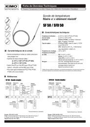
Technical Dat a <strong>Sheet</strong>Flush-mount pressure transmitterCPE 300NewNew• Ranges from 0/+10 Pa to -1000/+1000 Pa (according to the model)• Transmitter resolution at 0.1 Pa on CPE 301 (optional)• Configurable intermediate and centre zero ranges• Face calibration• Interchangeable Measuring Sensor (SPI technology)• Alternating display of 1 to 3 parameters• External transmitter inputs (<strong>KIMO</strong> Class 200 and 300)• 4-20 mA (4 wires) or 0-10V output, RS 232, 2 RCR relays 6A/230 Vac• 2 visual (dual color LED) and audible (buzzer - 80 dB) alarms• Output diagnostics• MODBUS network RS 485 system (optional)• Front made of brushed stainless steel or white lacquered,with electroluminescent displayPart numberTo order, just add the codes to complete the part number :CPE30Measuring range1 -100/+100 Pa2 -500/+500 Pa3 -1000/+1000 Pa-Front faceBIWhite lacquered stainless steelbrushed stainless steelExample : CPE302-B = flush-mount transmitter type <strong>CPE300</strong>, with a range of-500/+500 Pa, and a white lacquered stainless steel housing.Housing dimensionsFor the intermediate andcentre zero ranges, see“Configuration”.Transmitter featuresPressureMeasuring range ............................see “SPI features”Units of measurement....................Pa, mmH O, mbar, inWG2Accuracy *......................................± 0,5% of reading ± 1 Pa± 0,5% of reading ± 0.8 Pa (CPE 301 with 0.1Pa option)Zero drift .........................................none (see “self-calibration”)Resolution ......................................1 Pa - 0,1 mmH2O - 0,01 mbar - 0,01 InWGSelf-calibration...............................push-button or automatic (configurable)Type of fluid ...................................air and neutral gases* All accuracies indicated in this technical datasheet were stated in laboratory conditions, and can be guaranted formeasurements carried out in the same conditions, or carried out with calibration compensation.Housing featuresFront face..........................316L wire brushed stainless steel or white lacqueredBack housing....................flushmount, 304L stainless steelDimensions ......................see drawing alongsideDisplay ..............................electroluminescent alphanumeric (38 x 48 mm)........................................... 4 digits x 8 segments (first line : value of the measurement)........................................... 4 digits x 12 segments (second line : unit of measurement).............................................. protection screen made of PMMADisplay ..............................from 1 to 3 parameters, alternatively (3 seconds)Height of digits.................14 mmBack fittings .....................barbed fittings Ø 5,2 mmWeight ...............................690g
-SPI system featuresInterchangeable Pressure SensorThe SPI board (Interchangeable Pressure Sensor) includes apiezoresistive sensitive element with its digital electronic system. Thissystem is individually adjusted and records all the calibration parameters.Via the automatic recognition by the transmitter, this digital board is totallyinterchangeable. Maintenance, service and calibration are easilyperformed on site, with no need to stop the process.InnovationsAdjustable pressure connectionsThe CPE 300 has 2 adjustable pressure connections in front (A), coupled with 2pressure connections at the back (B).When installing, this system allows you to configure your pressure connections witha set of plugs (supplied with the transmitter).ABlack-Red+Examples of possible mountingsPlugsConfigurable intermediate and centre zero rangesProbe ref.SPI 100SPI 500SPI 1000Pressure range-100/+100 Pa-500/+500 Pa-1000/+1000 PaThe minimum configurable range is 10% of the full scale.Overpressure tolerated ............25 000 PaResponse time..........................1/e (63%) 0,3 sec.Type...........................................digitalDimensions...............................L = 60 mm, l = 25 mmWorking temperature...............0 to +50 °CStorage temperature................-10 to +70 °CB+ -+Open plugPlug+Plug--Self-calibrationClass 300 transmitters have a temperature compensation system from 0 to 50°C,and a self-calibration system, to guarantee an excellent long-term stability, alongwith a great measurement accuracy.Self-calibration principle: the microprocessor drives an electro-valve thatcompensates for any long-term drift of the sensitive element.Compensation is made by regular automatic adjustment of the zero.Truedifferential pressure measurement is then made regardless of the environmentalconditions of the transmitter.Electro-valve lifetime..............100-million cyclesBenefit.....................................no zero driftSelf-calibration frequency .....can be disabled or set between 1 and 60 min.Face calibrationThis innovative systemallows you to isolate theback pressure connections,and then to access thesensitive element (on theface) of the transmitter.Without unmounting thetransmitter, this systemallows you to calibrate byconnecting the transmitterto a pressure generator anda calibration bench.The calibration is easier andfaster.Plug+Red Black+ -CalibrationbenchRelays and AlarmsClass 300 transmitters have 4 stand-alone and configurable alarms :2 visual alarms (dual color LED) and 2 relays (contacts).You can set :- 1 or 2 set points (rising and falling action) for each alarm- the time-delay / 60 sec. max.- the alarm action (rising or falling)- the relay operation mode : positive or negative security-the audible alarm (buzzer) activation.Integration of pressure measurementThe pressure measurement element is very sensitive and reacts to pressurechanges. When making measurements in unstable air movement conditions, thepressure measurement may fluctuate. The integration coefficient (from 0 to 9)makes an average of the measurements ; this helps to avoid any excessivevariations and guarantees a stable measurement.Technical SpecificationsPower supply ...........................24 Vac / Vdc ±10%Output.......................................1 x 4-20 mA or 1 x 0-10 V (4 wires)maximum load : 500 Ohms (4-20 mA)minimum load : 1 K Ohms (0-10 V)Galvanic isolation....................on the outputConsumption ...........................5 VARelays.......................................2 RCR relays 6A / 230 VacVisual alarms ...........................2 dual color LEDAudible alarm...........................buzzerElectro-magnetical compatibility.......EN 61 326Electrical connection ................screw terminal block for cables Ø 1.5 mm² maxRS 485 communication...........digital : RTU Modbus protocol.................................................. communication speed configurable.................................................. from 2400 to 115200 BaudsRS 232 communication...........digital : ASCII, proprietary protocolWorking temperature (housing) ........0 to +50°CStorage temperature ..........................-10 to +70°CEnvironment........................................air and neutral gases
{ConnectionFront Pressure Connections+ -cBack pressureconnectionseRS 232 connector(LCC 300 software)dAnalogue outputaPower supplybRelay terminal blocksdaabRelay 2 Relay 1For 24 Vacpower supply modelsFor 24 Vdcpower supply models4-20 mA ...........currentGND.................ground0-10 V ..............voltage~ ~- +NO .............normally openCOM ..........commonNC .............normally closedNO .............normally openCOM ..........commonNC .............normally closedElectrical connections - as per NFC15-100 norm!This connection must be made by a qualified technician. Whilst making the connection, the transmitter must not be energized.Power supply connection :• For 24 Vdc power supply models :Output signal selectionvoltage (0-10 V) or current (4-20 mA)The on-off switch located on the left sideof the transmitter allows selection of therequired outputs.Connection of SUB-D15RS 232 and RS 485 (Modbus)(see e on connection drawing)87654315 14 13 12 11 10291Power supplyterminal block24 Vdcpower supply--+• For 24 Vac power supply models :230 VacPower supplyterminal blockPeNLpower supplyClass II~4 5Vac Vac~ ~24 Vac~230 Vac4 5+ORPeNLNPhpower supply4 5N L24 VacDown4-20 mAOutput connection :• 4-20 mA current output :4-20 mA GND 0-10 VOutputterminal blockRegulator displayor PLC/BMS+passive type -• 0-10 V voltage output :Regulator displayor PLC/BMSpassive typeUp0-10 VOutputterminal block-++4-20 mA GND 0-10 V--+Pin # Description1 NC *2 NC *3 NC *4 B - (RS485)5 A + (RS485)6 NC *7 NC *8 NC *9 RX (RS 232)10 NC *11 TX (RS 232)12 NC *13 NC *14 NC *15 GND (RS 232)! CAUTION :NC * --> DO NOT CONNECT
Digital communicationRS 232 communication• Via the RS 232 connection, CPE 300 can displayalternatively (every 3 sec) 1 or 2 parameters thatare measured by other <strong>KIMO</strong> Class 200 and 300transmitters.Benefit : the CPE 300 can display (in addition to thepressure) other parameters such as temperature andhumidity from a TH 200 (for example).• Via the RS 232 connection, you can also configureyour transmitter with the LCC-300 software.• The RS 232 connection cable is available in 2 m, 5 mor 10 m (maximum) lengths.Modbus network (RS 485 system)• Class 300 transmitters can be linkedin one network, on a RS 485 home bus.They can also be integrated into anexisting network.ConfigurationYou can configure all the parameters of the transmitter : units, measuringranges, alarms, outputs, channels, calculation formula.... via the differentmethods shown below.Via remote control (optional)This is convenient to configure the transmitters located in hard to reachpositions. Same method as with a keypad.Via software (optional) : on all models.Simple and user-friendly configuration. See LCC-300 user manual.Via MODBUS (optional) : on all models.Configuration of all parameters from your PC, via the supervision or dataacquisition software.Configurable analogue outputsConfigure the range according to your needs : outputs are automaticallyadjusted to the new measuring ranges.Range with centre zero (-50/0/+50 Pa),with offset zero (-30/0/+70Pa) orstandard range (0 /+100 Pa) => youcan configure your own intermediateranges according to your needs,between 10% and 100% of the fullscale. The minimum configurable rangeis 10% of the full scale.-1000V4 mARS 485RS 232• When a Class 200RS 232or 300 transmitter isconnected to aCP 300 (with RS 232 connection), all themeasurements can be given to the PLC/BMS via the RS 485, with only oneaddress for the 2 transmitters.• The RS 485 numerical communication is a 2-wire network, on which thetransmitters are connected in parallel. They are connected to a PLC/BMS via theRTU Modbus communication system. Since the CP 300 can be configured withthe keypad, the MODBUS enables remote configuration, to measure 1 or 2parameters, to see the status of the alarms...Range0New range-100 0 500V4 mA10V20 mA+100(Pa, mmH2O...)10V20 mA+100(Pa, mmH2O...)www.kimo.fr Distributed by :EXPORT DEPARTMENTTel : + 33. 1. 60. 06. 69. 25 - Fax : + 33. 1. 60. 06. 69. 29e-mail : export@kimo.frCalibrationAdjusting and calibration on site :The professional configuration interface,with a dynamic pressure calibrationbench, enables you to adjust andcalibrate your transmitters directly onsite or in laboratories.Certificate :• Class 300 transmitters are supplied with adjusting certificates.Calibration certificates are offered as an option.• The SPI sensitive elements (Interchangeable Pressure Sensor)are supplied with adjusting certificates.MountingTo install the transmitter on a wall, make a cutting of 196 x 70 mmin the wall. Then drill 4 holes around the cutting as shown below.Insert the transmitter into the wall and then, swrew the 4 screws(supplied with the transmitter).MaintenanceAvoid aggressive solvents.Protect the transmitter and probes from any cleaningproduct containing formol, which may be used forcleaning rooms or ducts.OptionsRS 485 digital output (Modbus network)LCC-300 configuration software, with RS 232 cableInfrared remote control for configurationCalibration certificateTransmitter resolution at 0.1 Pa (CPE 301)Optional accessoriesSliding fittingsConnection fittingsClear tubeOutput diagnostics :With this function, you can check with amultimeter (or a regulator/display, or aPLC/BMS) if the transmitter outputs workproperly. The transmitter output generatesa voltage of 0 V, 5 V and 10 V or a current of4 V, 12 V and 20 mA.Pressure connectionsThrough-connectionsRef. FT ang - CPE 300 - 05/09 D - RCS (24) Périgueux B349 282 095 Non-contractual document - We reserve the right to modify the characteristics of our products without prior notice