Integrated Magnetic for LLC Resonant Converter - CPES
Integrated Magnetic for LLC Resonant Converter - CPES
Integrated Magnetic for LLC Resonant Converter - CPES

You also want an ePaper? Increase the reach of your titles
YUMPU automatically turns print PDFs into web optimized ePapers that Google loves.
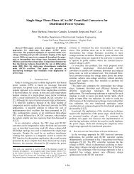
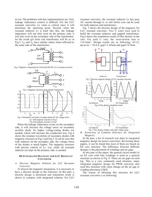
as Lm. The problems with this implementation are: first,leakage inductance control is difficult. For the <strong>LLC</strong>resonant converter, Lr value is critical since it willdetermine the operating point. Second, when theresonant inductor Lr is built like this, the leakageinductance will not only exist on the primary side, itwill also exist on the secondary side of the trans<strong>for</strong>mer.So the result get from real trans<strong>for</strong>mer will be as inFig.3. L lp and L ls have similar values when reflected tothe same side of the trans<strong>for</strong>mer.Lr 14uHTa4:1:11Lm60uH02bFig. 2 <strong>Magnetic</strong> components <strong>for</strong> Front End DC/DC <strong>LLC</strong> resonant converterabLlpLm60uHT4:1:1L ls1L ls2Fig. 3 <strong>Magnetic</strong> structures from Simple Trans<strong>for</strong>mer102resonant converter, the resonant inductor Lr has pureAC current through it, so soft ferrite core can be used<strong>for</strong> both inductor and trans<strong>for</strong>mer.Fig. 5 shows the discrete design of the magnetic <strong>for</strong><strong>LLC</strong> resonant converter. Two U cores were used tobuild the resonant inductor and gapped trans<strong>for</strong>mer.Fig.6 shows the simulation results of flux density in thecore. For each U core, the cross-section area is116.5mm 2 . Design results are as following: nl=12,np:ns:ns = 16:4:4, gap1=1.45mm and gap2=0.5mm.gap1nlInductornsnpTrans<strong>for</strong>mergap2Fig. 5 Discrete magnetic design of <strong>LLC</strong> resonant converterns(a) Inductor(b) Trans<strong>for</strong>merFig. 6 Flux density simulation result(a)Fig. 4 Simulation wave<strong>for</strong>m of output diodes D1 D2 voltage stress(a): with magnetic structure in Fig 2(b) with magnetic structure in Fig3When the leakage inductance exists on the secondaryside, it will increase the voltage stress on secondaryrectifier diode. So higher voltage-rating diodes areneeded, which will increase the conduction loss. Fig 4shows the simulate wave<strong>for</strong>ms of secondary diodes withmagnetic structure in Fig.2 and Fig.3. It can be seen thatwith inductor on the secondary side, the voltage stressof the diodes is much higher. The magnetic structurewith precise control of Lr, Lm, while all resonantinductor are kept on the primary side, is needed.III. INTEGRATED MAGNETIC FOR <strong>LLC</strong> RESONANTCONVERTERA. Discrete <strong>Magnetic</strong> Solution <strong>for</strong> <strong>LLC</strong> <strong>Resonant</strong><strong>Converter</strong>To discuss the magnetic integration, it is necessary tohave a discrete design as the reference. In this part, adiscrete design is presented and simulation result isshown to compare with integrated solution. For <strong>LLC</strong>(b)(a) Inductor(b) Trans<strong>for</strong>merFig. 7 Flux density change with input voltage rangeB. Extraction of Common Structure <strong>for</strong> <strong>Integrated</strong><strong>Magnetic</strong>In the past, a lot of research was done in integratedmagnetic design <strong>for</strong> power converters. Reviewing thosepapers, it can be found that most of them are based onEE core structure. The difference between differentdesigns is the placement of windings and air gaps.In this part of the paper, the general circuit model ofan EE core with four windings is used as a generalstructure as shown in Fig. 8. There are air gaps on eachleg. This is a very commonly used structure, manyintegrated magnetic design <strong>for</strong> PWM converter alsoused this structure with some change on the air gap orwinding placement [3][4].The reason of choosing this structure <strong>for</strong> <strong>LLC</strong>resonant converter is as following: