Integrated Magnetic for LLC Resonant Converter - CPES
Integrated Magnetic for LLC Resonant Converter - CPES
Integrated Magnetic for LLC Resonant Converter - CPES

You also want an ePaper? Increase the reach of your titles
YUMPU automatically turns print PDFs into web optimized ePapers that Google loves.
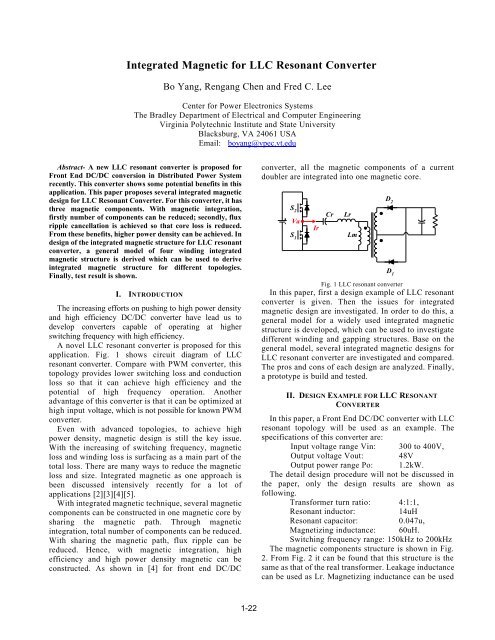
<strong>Integrated</strong> <strong>Magnetic</strong> <strong>for</strong> <strong>LLC</strong> <strong>Resonant</strong> <strong>Converter</strong>Bo Yang, Rengang Chen and Fred C. LeeCenter <strong>for</strong> Power Electronics SystemsThe Bradley Department of Electrical and Computer EngineeringVirginia Polytechnic Institute and State UniversityBlacksburg, VA 24061 USAEmail: boyang@vpec.vt.eduAbstract- A new <strong>LLC</strong> resonant converter is proposed <strong>for</strong>Front End DC/DC conversion in Distributed Power Systemrecently. This converter shows some potential benefits in thisapplication. This paper proposes several integrated magneticdesign <strong>for</strong> <strong>LLC</strong> <strong>Resonant</strong> <strong>Converter</strong>. For this converter, it hasthree magnetic components. With magnetic integration,firstly number of components can be reduced; secondly, fluxripple cancellation is achieved so that core loss is reduced.From these benefits, higher power density can be achieved. Indesign of the integrated magnetic structure <strong>for</strong> <strong>LLC</strong> resonantconverter, a general model of four winding integratedmagnetic structure is derived which can be used to deriveintegrated magnetic structure <strong>for</strong> different topologies.Finally, test result is shown.I. INTRODUCTIONThe increasing ef<strong>for</strong>ts on pushing to high power densityand high efficiency DC/DC converter have lead us todevelop converters capable of operating at higherswitching frequency with high efficiency.A novel <strong>LLC</strong> resonant converter is proposed <strong>for</strong> thisapplication. Fig. 1 shows circuit diagram of <strong>LLC</strong>resonant converter. Compare with PWM converter, thistopology provides lower switching loss and conductionloss so that it can achieve high efficiency and thepotential of high frequency operation. Anotheradvantage of this converter is that it can be optimized athigh input voltage, which is not possible <strong>for</strong> known PWMconverter.Even with advanced topologies, to achieve highpower density, magnetic design is still the key issue.With the increasing of switching frequency, magneticloss and winding loss is surfacing as a main part of thetotal loss. There are many ways to reduce the magneticloss and size. <strong>Integrated</strong> magnetic as one approach isbeen discussed intensively recently <strong>for</strong> a lot ofapplications [2][3][4][5].With integrated magnetic technique, several magneticcomponents can be constructed in one magnetic core bysharing the magnetic path. Through magneticintegration, total number of components can be reduced.With sharing the magnetic path, flux ripple can bereduced. Hence, with magnetic integration, highefficiency and high power density magnetic can beconstructed. As shown in [4] <strong>for</strong> front end DC/DCconverter, all the magnetic components of a currentdoubler are integrated into one magnetic core.D 2S 2Cr LrVaIrS 1LmD 1Fig. 1 <strong>LLC</strong> resonant converterIn this paper, first a design example of <strong>LLC</strong> resonantconverter is given. Then the issues <strong>for</strong> integratedmagnetic design are investigated. In order to do this, ageneral model <strong>for</strong> a widely used integrated magneticstructure is developed, which can be used to investigatedifferent winding and gapping structures. Base on thegeneral model, several integrated magnetic designs <strong>for</strong><strong>LLC</strong> resonant converter are investigated and compared.The pros and cons of each design are analyzed. Finally,a prototype is build and tested.II. DESIGN EXAMPLE FOR <strong>LLC</strong> RESONANTCONVERTERIn this paper, a Front End DC/DC converter with <strong>LLC</strong>resonant topology will be used as an example. Thespecifications of this converter are:Input voltage range Vin: 300 to 400V,Output voltage Vout: 48VOutput power range Po: 1.2kW.The detail design procedure will not be discussed inthe paper, only the design results are shown asfollowing.Trans<strong>for</strong>mer turn ratio: 4:1:1,<strong>Resonant</strong> inductor:14uH<strong>Resonant</strong> capacitor:0.047u,Magnetizing inductance: 60uH.Switching frequency range: 150kHz to 200kHzThe magnetic components structure is shown in Fig.2. From Fig. 2 it can be found that this structure is thesame as that of the real trans<strong>for</strong>mer. Leakage inductancecan be used as Lr. Magnetizing inductance can be used
as Lm. The problems with this implementation are: first,leakage inductance control is difficult. For the <strong>LLC</strong>resonant converter, Lr value is critical since it willdetermine the operating point. Second, when theresonant inductor Lr is built like this, the leakageinductance will not only exist on the primary side, itwill also exist on the secondary side of the trans<strong>for</strong>mer.So the result get from real trans<strong>for</strong>mer will be as inFig.3. L lp and L ls have similar values when reflected tothe same side of the trans<strong>for</strong>mer.Lr 14uHTa4:1:11Lm60uH02bFig. 2 <strong>Magnetic</strong> components <strong>for</strong> Front End DC/DC <strong>LLC</strong> resonant converterabLlpLm60uHT4:1:1L ls1L ls2Fig. 3 <strong>Magnetic</strong> structures from Simple Trans<strong>for</strong>mer102resonant converter, the resonant inductor Lr has pureAC current through it, so soft ferrite core can be used<strong>for</strong> both inductor and trans<strong>for</strong>mer.Fig. 5 shows the discrete design of the magnetic <strong>for</strong><strong>LLC</strong> resonant converter. Two U cores were used tobuild the resonant inductor and gapped trans<strong>for</strong>mer.Fig.6 shows the simulation results of flux density in thecore. For each U core, the cross-section area is116.5mm 2 . Design results are as following: nl=12,np:ns:ns = 16:4:4, gap1=1.45mm and gap2=0.5mm.gap1nlInductornsnpTrans<strong>for</strong>mergap2Fig. 5 Discrete magnetic design of <strong>LLC</strong> resonant converterns(a) Inductor(b) Trans<strong>for</strong>merFig. 6 Flux density simulation result(a)Fig. 4 Simulation wave<strong>for</strong>m of output diodes D1 D2 voltage stress(a): with magnetic structure in Fig 2(b) with magnetic structure in Fig3When the leakage inductance exists on the secondaryside, it will increase the voltage stress on secondaryrectifier diode. So higher voltage-rating diodes areneeded, which will increase the conduction loss. Fig 4shows the simulate wave<strong>for</strong>ms of secondary diodes withmagnetic structure in Fig.2 and Fig.3. It can be seen thatwith inductor on the secondary side, the voltage stressof the diodes is much higher. The magnetic structurewith precise control of Lr, Lm, while all resonantinductor are kept on the primary side, is needed.III. INTEGRATED MAGNETIC FOR <strong>LLC</strong> RESONANTCONVERTERA. Discrete <strong>Magnetic</strong> Solution <strong>for</strong> <strong>LLC</strong> <strong>Resonant</strong><strong>Converter</strong>To discuss the magnetic integration, it is necessary tohave a discrete design as the reference. In this part, adiscrete design is presented and simulation result isshown to compare with integrated solution. For <strong>LLC</strong>(b)(a) Inductor(b) Trans<strong>for</strong>merFig. 7 Flux density change with input voltage rangeB. Extraction of Common Structure <strong>for</strong> <strong>Integrated</strong><strong>Magnetic</strong>In the past, a lot of research was done in integratedmagnetic design <strong>for</strong> power converters. Reviewing thosepapers, it can be found that most of them are based onEE core structure. The difference between differentdesigns is the placement of windings and air gaps.In this part of the paper, the general circuit model ofan EE core with four windings is used as a generalstructure as shown in Fig. 8. There are air gaps on eachleg. This is a very commonly used structure, manyintegrated magnetic design <strong>for</strong> PWM converter alsoused this structure with some change on the air gap orwinding placement [3][4].The reason of choosing this structure <strong>for</strong> <strong>LLC</strong>resonant converter is as following:
To integrate two magnetic components, usually threemagnetic paths are needed. In the <strong>LLC</strong> resonantconverter, although there are three magneticcomponents, Lm and trans<strong>for</strong>mer T can be build withinan air-gapped trans<strong>for</strong>mer. There<strong>for</strong>e only two magneticcomponents: series resonant inductor Lr and gappedtrans<strong>for</strong>mer T are needed to be integrated. An EE corestructure will be a reasonable choice.n1*i1n2*i2Base on this circuit model, more integrated magneticstructures will be investigated.C. <strong>Integrated</strong> magnetic design A <strong>for</strong> <strong>LLC</strong> resonantconverterFrom discrete design, just combine them togetherwith an EE core, the two magnetic components can beintegrated into one, as shown in Fig. 11.nlf inpgap1n3*i3gap0n4*i4gap2Fig. 8 general magnetic structures <strong>for</strong> <strong>Integrated</strong> magneticThe proposed model is derived based on dualitymodeling theory [1]. Using this theory, the electricalcircuit model of a physical magnetic structure can beobtained. All the component parameters in the modelare related to the parameters of the physical magneticstructure. Fig 9 shows the reluctance model of magneticstructure shown in Fig. 8. Fig. 10 shows its equivalentelectrical circuit model. In the structure, there exist twosets of ideal trans<strong>for</strong>mer and three inductors.R1 R2lgap1R1=µ ⋅ Acn1*i1n3*i3R0n2*i2n4*i4lgap2R2=µ ⋅ Aclgap0R0=µ ⋅ AcFig. 9 Reluctance model of general integrated magnetic structureThe turns ratio of the two ideal trans<strong>for</strong>mer are same,as in the real physical structure. The three inductorscorrespond to the three air gaps and they are allreflected to first winding n1. They can also be reflectedto other windings as necessary. The values of eachinductor are given in Fig. 13.n3n1:n1L1L0L2n1:n2n42n1L1=R12n1L2=R22n1L0=R0Fig. 10 Circuit model of general integrated magnetic structuregap1InductorLegf cf tnsnsTrans<strong>for</strong>merLeggap2Fig. 11 <strong>Integrated</strong> <strong>Magnetic</strong> Designs AE42/21/20 core is used. The cross-section area of is233mm 2 . For the outer legs, the cross-section area is thesame as discrete design. Turn number nl, np and ns isthe same as in discrete design. For this design, theinductor and trans<strong>for</strong>mer design is decoupled. Discretedesign procedure still can be used. Fig. 9 shows thesimulation result of <strong>for</strong> this structure.Fig. 12 Flux density simulation result <strong>for</strong> Design AIt can be seen from the simulation result that <strong>for</strong>inductor and trans<strong>for</strong>mer leg, the flux density is thesame as discrete design. But <strong>for</strong> center leg, the fluxdensity is much smaller than the discrete case. This willgreatly reduce the magnetic loss in the big part of themagnetic component.Fig. 13 Center leg flux density <strong>for</strong> different input voltage
Fig. 10 shows the center leg flux density <strong>for</strong> wholeinput voltage range. Compare with the discrete design,the flux density is only half of the trans<strong>for</strong>mer leg andmuch smaller than inductor leg within all input voltagerange.The shortcoming of this structure is the gapping. Inthis structure, two E cores are used. The air gap is onthe two outer legs while there is no air gap on the centerleg. This structure is not good in several senses: first,this core structure is standard. The standard corenormally has air gap on the center leg or no air gap atall. Second, it is not a mechanical stable structure.A desired core structure will have air gap on centerleg or same air gap <strong>for</strong> all three legs.D. <strong>Integrated</strong> magnetic design B <strong>for</strong> <strong>LLC</strong> resonantconverterAs discussed previously, the air gapping in structureA is difficult to implement. In this part, the structurewith same air gap <strong>for</strong> all three legs will be discussed.The winding structure is shown in Fig. 14.gap11 nl 2 3 np 4f igap0f cf tns nsgap2Fig. 14 <strong>Integrated</strong> <strong>Magnetic</strong> Designs AThe electrical model of this structure can be obtainedfrom the proposed general structure. Compare thisstructure with the general structure; design B has onlyone winding on the left leg. By simplifying the generalmodel, the following circuit model can be obtained, asshown in Fig. 15.L01234L1L2 n1 n3Fig. 15 Electrical circuit model of integrated magnetic structure BBase on the electrical structure, there are two possibleconnections of the primary windings. Fig.16 shows oneconnection method, which connects the dot-markedterminal with unmarked terminal.There are two operation modes <strong>for</strong> this circuit asshown in Fig. 17. One mode is n3 is connected tooutput. The other mode is both secondary windings arenot connected. The equivalent circuit <strong>for</strong> these twomodes will be derived separately.n2n3123L1L0L2 n1 n34 n3Fig. 16 Electrical model of connecting dot-marked terminal with unmarkedterminalv in3i 0n1 n31+ L 0+Li 1 L v n3211 --i in+v 2-(a)n2Von2i 0i in n11+ L 0+Li 1 L v211 -v in+v-2-3(b)Fig.17 Two operation modes <strong>for</strong> <strong>LLC</strong> resonant converterFor operation mode (a), the following equations canbe derived:di1n2L 1 + v1= v in(1)dt n1di0n2L 0 + v1+ v1= v in(2)dt n1nv = 11Von3(3)i 0+ i 1= i in(4)From (1) to (4), the relationship of the input voltage,input current and output voltage can be expressed asfollowing:L1⋅L0diin1 L1vin = + Vo ( n2+ n1) (5)L1+ L0dt n3L1+ L0From (5), the equivalent circuit during this mode canbe obtained, as shown in Fig.18.1+v in-3i ini 0L rL mFig.18 Equivalent-circuit <strong>for</strong> mode (a)In this circuit, Lr, Lm and Na are given by thefollowing equations:L1⋅L0Lr = (6)L1+ L0L1na = n2+ n1(7)L1+ L0Operation mode (b) need to be analyzed to find outLm. Following the same procedure as analyzing mode(a), another set of equations of mode (b) can benan3n3Von2
obtained, which will not be listed here. From mode (b)equations, the expression of Lm can be obtained, asshown in (8)22 na L1+ L0Lm = L ⋅ ⋅n12(8)L1+ L2+ L0For the connection method shown in Fig. 19, theexpressions of Lr, na and Lm can be obtain by followingthe same derivations as above. Those values are givenby (9)-(11), respectively.1234L1L0L2 n1 n3Fig.19 Electrical model of connecting dot-marked terminalsL1⋅L0Lr = (9)L1+ L0L1na = n2− n1(10)L1+ L022 na L1+ L0Lm = L ⋅ ⋅n12(11)L1+ L2+ L0Using the above-proposed model, the integratedmagnetic component <strong>for</strong> this application can bedesigned. An integrated magnetic as shown in Fig.16 isdesigned as an example. To get the same value asdiscrete design (Lr=14uH, Lm=60uH and turnratio=16:4), the design results of the integrated magneticcomponent are:Nl=9, Np=13, Ns=4 and air gap is 0.56mm <strong>for</strong> alllegs.Fig.20 shows the simulated flux density on each leg.From simulation result it can be found that the fluxdensity on center leg is greatly reduced. So with thisintegrated magnetic structure, the core loss could begreatly reduced. Also, with this structure, the air gap isthe same <strong>for</strong> all legs, which is easier to manufacture andhas less mechanical problem.Fig. 20 <strong>Integrated</strong> <strong>Magnetic</strong> structure 3 and flux density in each legn2n3IV. TEST RESULTFrom above discussions, it can be found thatintegrated magnetic structure B provides betterelectrical per<strong>for</strong>mance due to the flux ripplecancellation effect in the center leg of the E core. It alsohas better manufacture capability and better mechanicalstability due to factor that the three legs have the samelength of air gap. To verify the design results, aprototype of integrated magnetic structure B isconstructed and tested. The parameters are:Lr=14uH, Lm=60uH and turn ratio=16:4.Nl=9, Np=13, Ns=4 and air gap is 0.56mm <strong>for</strong> alllegs.The converter specs are:Input voltage range: 300 to 400VOutput voltage: 48VOutput power: 1000WSwitching frequency range: 140kHz to 200kHzFig. 21 Simulation wave<strong>for</strong>m & test wave<strong>for</strong>m <strong>for</strong> 400V input, fs=200kHz,full loadFig. 22 Simulation wave<strong>for</strong>m & test wave<strong>for</strong>m <strong>for</strong> 300V input, fs=140kHz,full loadV. CONCLUSIONIn this paper, integrated magnetic design <strong>for</strong> <strong>LLC</strong>resonant converter is discussed. Compared with discreteapproach, integrated magnetic can reduce thecomponents count and reduce the total core loss.Several integrated magnetic structures are alsodiscussed in this paper. <strong>Integrated</strong> magnetic structure Ais not preferred because the air gaps are only located onthe outer legs, which will increase the complexity ofmanufacturing and decrease the mechanical stability. Toinvestigate more structure, an electrical model <strong>for</strong>general structure is proposed based on the duality
theory. Base on this model, structure B is proposed andanalyzed. Compare with structure A, structure Bprovides better mechanical structure and better fluxdistribution. A prototype of structure B was constructedand tested. The experimental results verified theanalysis and design results.REFERENCES[1] J.K. Watson, Applications of Magnetism, 1985[2] Kats, A.; Ivensky, G.; Ben-Yaakov, “Application of integratedmagnetic in resonant converters”. APEC '97 Conference Proceedings1997, Twelfth Annual, Volume: 2, 1997 Page(s): 925 -930 vol.2[3] Chen, W.; Hua, G.; Sable, D.; Lee, F., “Design of high efficiency,low profile, low voltage converter with integrated magnetics” APEC '97Conference Proceedings 1997., Twelfth Annual , Volume: 2 , 1997Page(s): 911 -917 vol.2[4] Peng Xu; Qiaoqiao Wu; Pit-Leong Wong; Lee, F.C., “A novelintegrated current doubler rectifier” APEC 2000. Fifteenth AnnualIEEE , Volume: 2 , 2000 Page(s): 735 -740 vol.2[5] Bassett, I.A. “Constant frequency ZVS converter with integratedmagnetics”, APEC '92. Conference Proceedings 1992., Seventh Annual ,1992 Page(s): 709 -716