Matrix Converter Topologies With Reduced Number of ... - CPES
Matrix Converter Topologies With Reduced Number of ... - CPES
Matrix Converter Topologies With Reduced Number of ... - CPES

You also want an ePaper? Increase the reach of your titles
YUMPU automatically turns print PDFs into web optimized ePapers that Google loves.
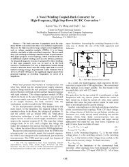
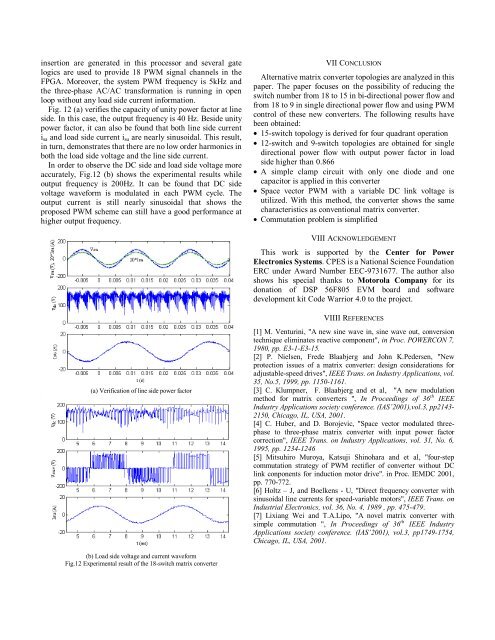
insertion are generated in this processor and several gatelogics are used to provide 18 PWM signal channels in theFPGA. Moreover, the system PWM frequency is 5kHz andthe three-phase AC/AC transformation is running in openloop without any load side current information.Fig. 12 (a) verifies the capacity <strong>of</strong> unity power factor at lineside. In this case, the output frequency is 40 Hz. Beside unitypower factor, it can also be found that both line side currenti sa andloadsidecurrenti su are nearly sinusoidal. This result,in turn, demonstrates that there are no low order harmonics inboth the load side voltage and the line side current.In order to observe the DC side and load side voltage moreaccurately, Fig.12 (b) shows the experimental results whileoutput frequency is 200Hz. It can be found that DC sidevoltage waveform is modulated in each PWM cycle. Theoutput current is still nearly sinusoidal that shows theproposed PWM scheme can still have a good performance athigher output frequency.VII CONCLUSIONAlternative matrix converter topologies are analyzed in thispaper. The paper focuses on the possibility <strong>of</strong> reducing theswitch number from 18 to 15 in bi-directional power flow andfrom 18 to 9 in single directional power flow and using PWMcontrol <strong>of</strong> these new converters. The following results havebeen obtained:• 15-switch topology is derived for four quadrant operation• 12-switch and 9-switch topologies are obtained for singledirectional power flow with output power factor in loadside higher than 0.866• A simple clamp circuit with only one diode and onecapacitor is applied in this converter• Space vector PWM with a variable DC link voltage isutilized. <strong>With</strong> this method, the converter shows the samecharacteristics as conventional matrix converter.• Commutation problem is simplifiedVIII ACKNOWLEDGEMENTThis work is supported by the Center for PowerElectronics Systems. <strong>CPES</strong> is a National Science FoundationERC under Award <strong>Number</strong> EEC-9731677. The author alsoshows his special thanks to Motorola Company for itsdonation <strong>of</strong> DSP 56F805 EVM board and s<strong>of</strong>twaredevelopment kit Code Warrior 4.0 to the project.(a) Verification <strong>of</strong> line side power factorVIIII REFERENCES[1]M.Venturini,"Anewsinewavein,sinewaveout,conversiontechnique eliminates reactive component", in Proc. POWERCON 7,1980, pp. E3-1-E3-15.[2] P. Nielsen, Frede Blaabjerg and John K.Pedersen, "Newprotection issues <strong>of</strong> a matrix converter: design considerations foradjustable-speed drives", IEEE Trans. on Industry Applications, vol.35, No.5, 1999, pp. 1150-1161.[3] C. Klumpner, F. Blaabjerg and et al, "A new modulationmethod for matrix converters ", In Proceedings <strong>of</strong> 36 th IEEEIndustry Applications society conference. (IAS’2001),vol.3, pp2143-2150, Chicago, IL, USA, 2001.[4] C. Huber, and D. Borojevic, "Space vector modulated threephaseto three-phase matrix converter with input power factorcorrection", IEEE Trans. on Industry Applications, vol. 31, No. 6,1995, pp. 1234-1246[5] Mitsuhiro Muroya, Katsuji Shinohara and et al, "four-stepcommutation strategy <strong>of</strong> PWM rectifier <strong>of</strong> converter without DClink conponents for induction motor drive". in Proc. IEMDC 2001,pp. 770-772.[6] Holtz – J, and Boelkens - U, "Direct frequency converter withsinusoidal line currents for speed-variable motors", IEEE Trans. onIndustrial Electronics, vol. 36, No. 4, 1989 , pp. 475-479.[7] Lixiang Wei and T.A.Lipo, "A novel matrix converter withsimple commutation ", In Proceedings <strong>of</strong> 36 th IEEE IndustryApplications society conference. (IAS’2001), vol.3, pp1749-1754,Chicago, IL, USA, 2001.(b) Load side voltage and current waveformFig.12 Experimental result <strong>of</strong> the 18-switch matrix converter