Reflection Model Design for Wall-E and Up - Self Shadow
Reflection Model Design for Wall-E and Up - Self Shadow
Reflection Model Design for Wall-E and Up - Self Shadow

You also want an ePaper? Increase the reach of your titles
YUMPU automatically turns print PDFs into web optimized ePapers that Google loves.
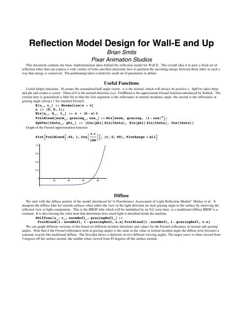
<strong>Reflection</strong> <strong>Model</strong> <strong>Design</strong> <strong>for</strong> <strong>Wall</strong>-E <strong>and</strong> <strong>Up</strong>Brian SmitsPixar Animation StudiosThis document contains the basic implementation ideas behind the reflection model <strong>for</strong> <strong>Wall</strong>-E. The overall idea is to pick a fixed set ofreflection lobes that can express a wide variety of looks <strong>and</strong> then determine how to partition the incoming energy between those lobes in such away that energy is conserved. The partitioning takes a relatively small set of parameters to define.Useful FunctionsUseful helper functions. H creates the normalized half angle vector. n is the normal, which will always be positive z. SphVec takes theta<strong>and</strong> phi <strong>and</strong> creates a vector. Theta of 0 is the normal direction (+z). FrnlBlend is the approximate Fresnel function introduced by Schlick. Theversion here is generalized a little bit so that the first argument is the reflectance at normal incidence angle, the second is the reflectance atgrazing angle (always 1 <strong>for</strong> st<strong>and</strong>ard Fresnel)H@u_, v_D := Normalize@u + vDn := 80, 0, 1
2 <strong>Wall</strong>ESiggraph.nbPolarPlotB:PDiffuseBSphVecB 5 p180 , - p 2 F, SphVecBtheta - p 2 , p F, 0.04, 1F,2PDiffuseBSphVecB 85 p180 , - p 2 F, SphVecBtheta - p 2 , p F, 0.04, 1F>, 8theta, 0, p, 8theta, 0, p
4 <strong>Wall</strong>ESiggraph.nbTo get the diffN <strong>and</strong> diffG terms that define the diffuse response <strong>for</strong> a layer we need to look at the metallic parameter, the roughnessparameter, <strong>and</strong> the surface color (surfColor). The default dielectric response is .05 (with the option to adjust this by the user, corresponding toadjusting the index of refraction of the surface), <strong>and</strong> <strong>for</strong> a metal, it is 1. At grazing angle the default is 1 (also adjustable <strong>for</strong> various usabilityreasons). Roughness blends both of these to 0. Because of the linearity of the FrnlBlend function we can move all of the terms into theFrnlBlend term <strong>for</strong> the light once the view is fixed. The results are checked <strong>for</strong> two different roughnesses belownRefl := Mix@.05, 1, metallicDgRefl := 1diffN := surfColor * Mix@H1 - nReflL FrnlBlend@1 - nRefl, 1 - gRefl, Vdir.nD, 1, roughDdiffG := surfColor * Mix@H1 - gReflL FrnlBlend@1 - nRefl, 1 - gRefl, Vdir.nD, 1, roughDmetallic = 0;rough = 0;surfColor = 1;Vdir = 80, 0, 1
<strong>Wall</strong>ESiggraph.nb 5PSpecular@u_, v_, r_, specNormal_, specGrazing_D :=PSpecDist@n.H@u, vD, rD FrnlBlend@specNormal, specGrazing, u.H@u, vDDIn.u 2 + n.v 2 - n.u n.vM 4PlotB:PSpecularBSphVecB 0 p180 , - p 2 F, SphVecBtheta - p 2 , p F, 0.5`, 0.85`, 1F,2PSpecularBSphVecB 0 p180 , - p 2 F, SphVecBtheta - p 2 , p F, 0.2`, 0.85`, 1F,2PSpecularBSphVecB 0 p180 , - p 2 F, SphVecBtheta - p 2 , p F, 0.05`, 0.85`, 1F>,28theta, 0, p
6 <strong>Wall</strong>ESiggraph.nbSphericalPlot3DBPSpecularBSphVecB 85 p180 , - p F, SphVec@theta, phiD, 0.1`, 0.05`, 1F Cos@thetaD,2:theta, 0, p >, 8phi, 0, 2 p, 8phi, 0, 2 p, 8phi, 0, 2 p, 8phi, 0, 2 p
<strong>Wall</strong>ESiggraph.nb 7powerR@r_D := -Log@0.1DSinA 1 H10 rL pE2180This gives us two functions, PSpecular, <strong>and</strong> a P<strong>Reflection</strong>, that define two highlight lobes. As long as we partition the normal <strong>and</strong> grazingweights passed in to these functions so that they sum to less than 1 we will conserve energy. We distribute the energy between the two lobesbased on roughness, so that at roughness 0 we have a weight of 1 on reflection <strong>and</strong> a weight of 0 on specular <strong>and</strong> the tightest reflection cone wecan effectively use. The specular cone starts out wider <strong>and</strong> grows faster, but it has a weight of 0 so it isn't seen. As roughness increases thereflection lobe widens <strong>and</strong> the weight decreases(reflections blur <strong>and</strong> fade away) both due to the blend between specular <strong>and</strong> reflection <strong>and</strong>because of a (1-rough) term that causes the surface to become completely diffuse at roughness 1, the broader highlight from the specular alsowidens, <strong>and</strong> first the specular weight increases because of the blending function <strong>and</strong> eventually the (1-rough) term causes even the specular tofade away. For efficiency reasons we have reflection fade to 0 at an intermediate roughness value so that we do not need to compute expensivereflections. Specular is only computed directly from lights <strong>and</strong> needs to be present even <strong>for</strong> very rough surfaces so that lighters could get a rimlighting effect. The resulting weights are fed into the PSpecular <strong>and</strong> P<strong>Reflection</strong> functions.reflRatio := Max@H1 - 2 * roughL^3, 0DnRefl := Mix@.05, surfColor, metallicDgRefl := 1;specN := H1 - reflRatioL * nRefl * H1 - roughLspecG := H1 - reflRatioL * gRefl * H1 - roughLreflN := reflRatio * nRefl * H1 - roughLreflG := reflRatio * gRefl * H1 - roughLTransmissionFor transmission we are taking energy that would have ended up in diffuse (due to the Fresnel weights) <strong>and</strong> instead distributing it into eithertransmitted diffuse, transmitted specular, or refraction. Each of these three lobes has a <strong>for</strong>m exactly like its front side equivalent. Transmissionwas meant to be used mostly on either thin film objects, or objects where a highly accurate energy transfer wasn't necessary. It was notdesigned <strong>for</strong> accurate rendering of glass objects. The view direction was refracted through the surface based on the index of refraction to get arefraction direction. That was then reflected off the surface to get a view direction on the back side of the surface that would put the center ofthe highlight in the correct refracted direction. No attempt was made to change cone angles based on index of refraction, or even deal correctlywith total internal reflection. Those concessions were acceptable at that time.Two parameters drive transmission. The first of these, clear, determines what fraction of the light that enters the surface (based on theFresnel weights) passes straight through the surface, affected only by the surface color. This is a description of how much scattering happensinside the material, as opposed to the scattering that happens at the interface due to roughness. A non-transparent material would have a clearvalue of 0, as all light that enters the surface is scattered. All scattered light is diffuse. The second parameter, back, is a description ofwhether the scattered light (diffuse) passes through the surface <strong>and</strong> exits the opposite side, or if it exits on the side the light shines on. A nontransparentmaterial would have a back value of 0 saying that all light that enters the material from the front <strong>and</strong> isn't attenuated by the surfacecolor exits from the front.We can now rewrite the expressions <strong>for</strong> the front side weights <strong>and</strong> add in expressions <strong>for</strong> the back side using these additional two terms.While the expressions get messier, we are still just blending between sets of energy conserving behaviors.First the diffuse terms:clear = .25;back = .5;nRefl := Mix@.05, 1, metallicDgRefl := 1dN := Mix@H1 - clearL H1 - nReflL FrnlBlend@1 - nRefl, 1 - gRefl, Vdir.nD, 1 roughDdG := Mix@H1 - clearL H1 - gReflL FrnlBlend@1 - nRefl, 1 - gRefl, Vdir.nD, 1, roughDdiffN := surfColor * dN * H1 - backLdiffG := surfColor * dG * H1 - backLdiffTN := surfColor * dN * backdiffTG := surfColor * dG * backNow the specular <strong>and</strong> reflection terms. Transparent metals tend not to make much sense, but there is no easy way to kill the behavior whenmetallic is an intermediate value. The two color terms tend to minimize any transmission. As in the diffuse terms, there is a 1-sG term which isoften 0, but if you include the ability to adjust Fresnel behavior at normal <strong>and</strong> grazing angles then that is not always true. While this makes nosense on a real surface, it may make sense when a material is meant to represent an aggregate of lots of small transparent geometry.
<strong>Wall</strong>ESiggraph.nb 9ConclusionsLots of the details in this model are based on an ever changing set of user requirements. The choice of lobe <strong>for</strong> the highlights <strong>for</strong> example iseasily changed as long as the new lobe also integrates to one or less over all incident angles. The mapping from roughness to cone angle <strong>and</strong>the transitions of weights as roughness changes must make the people who will use it happy. The exact specification of behavior at roughness 1is also arbitrary, <strong>and</strong> the layering approaches could be made either simpler or more complicated <strong>and</strong> still work fine <strong>for</strong> partitioning energy.Many of the decisions presented made more sense in 2006 on a film taking the first steps away from a completely non-physical model than theywould in a culture already used to physically based shading. For example, separating specular <strong>and</strong> reflection probably doesn't make sense at theinterface level any more. Internally, the separation may help when layering surfaces with broad highlights <strong>and</strong> surfaces with sharp highlights.If more separation is needed in these cases it might even be beneficial to keep separate normals <strong>for</strong> each of the highlight lobes.The key benefits are a fixed scattering model with a fixed amount of data required to drive it, <strong>and</strong> an approach to layering that gives the userspredictable <strong>and</strong> plausible results. With this we can map the model quite easily onto graphics hardware as well as make the lighting kernelinside of RenderMan shaders as efficient as possible. This is true <strong>for</strong> older lighting kernels as well as newer Monte Carlo based lightingkernels. For the users, the ability to get a wide range of appearances with a few parameters is very beneficial. It is also helpful to have the coreparameters be independent in the sense that adjusting one doesn't require a counteracting adjustment to another in order to maintain a plausibleor energy conserving material.