HM-G Model Installation and Maintenance Guide - DENSO Robotics
HM-G Model Installation and Maintenance Guide - DENSO Robotics
HM-G Model Installation and Maintenance Guide - DENSO Robotics

You also want an ePaper? Increase the reach of your titles
YUMPU automatically turns print PDFs into web optimized ePapers that Google loves.
Chapter 3 <strong>Maintenance</strong> <strong>and</strong> Inspection........................................................................................................................ 493.1 <strong>Maintenance</strong> & Inspection Intervals <strong>and</strong> Purposes ............................................................................................. 493.2 Daily Inspections................................................................................................................................................. 503.2.1 Check Items.................................................................................................................................................. 503.3 Quarterly Inspections .......................................................................................................................................... 513.3.1 Check Items <strong>and</strong> Lubrication........................................................................................................................ 513.3.2 Cleaning the Cooling Fan Filters in the Robot Controller............................................................................ 513.4 Semiyearly Inspections ....................................................................................................................................... 523.4.1 Lubrication ................................................................................................................................................... 523.5 Biennial Inspections ............................................................................................................................................ 533.5.1 Battery Replacement <strong>and</strong> Belt Inspection..................................................................................................... 533.5.2 Replacing the Encoder Backup Battery........................................................................................................ 543.5.3 Replacing the Memory Backup Battery ....................................................................................................... 573.5.4 Setting the Next Battery Replacement Date ................................................................................................. 573.6 Supplies for <strong>Maintenance</strong>.................................................................................................................................... 583.7 Replacing Fuses <strong>and</strong> Output ICs ......................................................................................................................... 583.8 Checking the Odometer <strong>and</strong> Trip Meter.............................................................................................................. 593.8.1 Displaying the Odometer <strong>and</strong> Trip Meter..................................................................................................... 593.8.2 Resetting the Trip Meter to Zero .................................................................................................................. 613.9 Checking the Controller ON-Time <strong>and</strong> the Robot Running Time <strong>and</strong> Resetting Their User Counters............... 623.9.1 Displaying the Controller ON-time <strong>and</strong> the Robot Running Time ............................................................... 623.9.2 Resetting the User Counters of the Controller ON-Time <strong>and</strong> the Robot Running Time .............................. 643.10 Backing up Projects............................................................................................................................................. 663.10.1 Back up project data ..................................................................................................................................... 663.10.2 Transfer arm data.......................................................................................................................................... 68
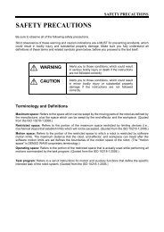
1000 or less20 or more100 100pipe500 or moreCaution (1) When the robot operates at high speed, the robot mountundergoes large reaction forces. The mount must be rigidenough so that it will not vibrate or be displaced due toreaction forces. It is also advisable to mechanically join therobot mount with heavy equipment.(2) Some mounts may produce a resonance sound (howling). Ifthis sound is loud, increase the rigidity of the mount orslightly modify the robot speed.Robot Mount Sample for Floor-mount TypeStrutMounting face350 350 20or more100 100 t6.0(square steel pipe)Caution (1) When the robot operates at high speed, the top platestructure undergoes large reaction forces. The robot mountmust be vibration-proof so that the top plate will not vibratedue to reaction forces. Also it must be designed to beseparated from other top plate structures in the equipment.(2) Some mounts may produce a resonance sound (howling). Ifthis sound is loud, increase the rigidity of the mount orslightly modify the robot speed.Robot Mount Sample for Overhead-mount Type3
1.2 Mounting the Robot UnitCaution(1) Before h<strong>and</strong>ling or installing the robot unit, be sure to read"SAFETY PRECAUTIONS, <strong>Installation</strong> Precautions."(2) The grease is applied to the shaft <strong>and</strong> rack of the Z-axis forlubrication <strong>and</strong> rust-proof. Do no touch or wipe the shaft <strong>and</strong>rack so as to keep rust-proof.(3) For UL-Listed robot units, do not move the 1st arm byholding its cover.1.2.1 Transporting the Floor-Mount TypeThis section gives the typical installation procedure assuming that you have set up therobot mount bed <strong>and</strong> prepared robot mounting bolt holes in it. If you have not done ityet, first read Section 1.2.3 "Securing the Robot Unit."Caution(1) The installation jobs should be h<strong>and</strong>led by at least twopersons.Robot unit weight: Approx. 56 kg (124 lbs)(2) Be sure to put on a helmet, safety shoes, <strong>and</strong> gloves.Step 1 Disconnect the motor cable, encoder cable, air pipes, h<strong>and</strong>, <strong>and</strong> tools from the robotunit, if mounted.(HS-G illustration tentatively used)Disconnect the motor cable, encoder cable, <strong>and</strong> others.4
Step 2 Turn the 2nd axis until it comes into contact with the mechanical end in order to keepthe safe position. Then remove the four bolts <strong>and</strong> release the robot unit from thepallet.Caution: When worker A is removing those bolts, worker B shouldsupport the 1st-axis arm to prevent the robot unit fromoverturning.(<strong>HM</strong>-G)Step 3 Transport the robot unit to the mounting position using the crane <strong>and</strong> eyebolts.Caution (1) Since the robot unit weighs approx. 56 kg (124 lbs),prepare a crane <strong>and</strong> forklift with a hoisting load of 0.2 tonor more.(2) The mounting job must be h<strong>and</strong>led by at least twopersons including a qualified operator for sling, crane <strong>and</strong>forklift operation.(3) Be sure to put on a helmet, safety shoes, <strong>and</strong> gloves.(4) After the mounting job, remove the eyebolts from therobot unit <strong>and</strong> store them.(<strong>HM</strong>-G)Step 3 Put the robot unit on the mount bed <strong>and</strong> secure it with four bolts temporarily.Step 4 Fix the robot unit, referring to Section 1.2.3 "Securing the Robot Unit."Tightening torque: 128 20 Nm (For <strong>HM</strong>-G series)5
1.2.2 Transporting the Overhead-Mount Type (<strong>HM</strong>S-G series)This section gives the typical installation procedure of the robot unit.Caution(1) Since the robot unit weighs approx. 56 kg (124 lbs), preparea crane <strong>and</strong> forklift with a hoisting load of 0.2 ton or more.(2) The overhead mounting job must be h<strong>and</strong>led by at least twopersons including a qualified operator for sling, crane <strong>and</strong>forklift operation.(3) Be sure to put on a helmet, safety shoes, <strong>and</strong> gloves.Step 1 When unpacked, the overhead-mount robot unit is fastened with rope as shownbelow. Make sure that the robot's 2nd-axis arm cannot rotate.Caution: NEVER remove the 2nd-axis arm fixing rope until theinstallation of the robot unit is completed.This is to prevent the robot arm from rotating unexpectedlydue to gravity.6
Step 2 As illustrated below, wind the belt sling around the 1st arm one turn.Step 3 Load the eyes of the belt sling on the hook of the crane.Wire (Belt sling)(HS-G illustration tentatively used)Step 4 Remove the four bolts <strong>and</strong> release the robot unit from the pallet.Caution: When worker A is removing those bolts, worker B shouldsupport the robot unit as shown below to prevent it fromoverturning.7
Step 5 While keeping the robot posture, slowly hoist the robot unit with the crane.Caution: Before starting this job, make the work floor clear ofobstacles.Step 6 Hoist the robot unit with the crane up to the height where the robot unit can be turnedupside down, stop the crane, <strong>and</strong> have two workers turn the robot unit upside downas shown below.8
Step 7 While having two workers keep the robot unit in the upside-down position, slowlyhoist the robot unit with the crane so that the robot base comes into contact with therobot installation face of the overhead-mount frame. Secure the robot unit with fourmounting bolts temporarily.Step 8 Firmly secure the robot unit, referring to Section 1.2.3, "Securing the Robot Unit."Tightening torque: 128 20 NmStep 9 After completing bolting, unhook the belt sling from the crane <strong>and</strong> then remove the2nd-axis arm fixing rope.Caution: Store the 2nd-axis arm fixing rope for future removal of therobot unit. When removing the robot unit, secure the 2ndarm with the rope to prevent the 2nd arm from rotating.9
1.2.3 Securing the Robot Unit(1) According to the dimensions specified in the figure below, drill four robot fixing holes <strong>and</strong> twodowel pin holes in the robot mount where the robot unit is to be anchored.Drilling in the robot mountDrilling in the robot mountFour robot fixing holesFor <strong>HM</strong>/<strong>HM</strong>S-G seriesM12 bolt holes a minimum of 20 mm deepTwo holes fordowel pinsFor diamond-shaped pinFor internally-threadedpositioning pin6H7 dia. hole a minimum of 12 mm deep8H7 dia. hole a minimum of 12 mm deep(2) Drive a diamond-shaped pin into the hole (<strong>HM</strong>/<strong>HM</strong>S-G: 6H7 dia.) so that the pin becomesoriented as shown below.(3) Drive an internally-threaded positioning pin into the hole (<strong>HM</strong>/<strong>HM</strong>S-G: 8H7 dia.).Caution: Never skip this step. These dowel pins may reduce chance of drop offof the robot unit during maintenance <strong>and</strong> misalignment due tovibration.(4) Put the robot unit on the robot mount, following the transport instructions given in Section1.2.1 "Transporting the Floor-Mount Type" or Section 1.2.2 "Transporting theOverhead-Mount Type."(5) Secure the robot unit with four bolts <strong>and</strong> plain washers.Fixing bolts: M12 x 35 mm, JIS strength class: 12.9 (For <strong>HM</strong>/<strong>HM</strong>S-G series)Tightening torque: 128 20 Nm (For <strong>HM</strong>/<strong>HM</strong>S-G series)(For <strong>HM</strong>/<strong>HM</strong>S-G series)Bolt Positions for Securing the Robot Unit10
1.2.4 Grounding the Robot UnitGround the grounding terminal of the robot unit using a wire of 5.5 mm 2 or more.Caution: Use a dedicated grounding wire <strong>and</strong> grounding electrode. Do notshare them with other power facilities or welding machines.Grounding the Robot Unit11
1.3 Installing the Robot ControllerFor the installing procedures of the robot controller, refer to the RC7M CONTROLLERMANUAL, Section 6.2 "Installing the Robot Controller."1.4 Electrical Wiring <strong>and</strong> Air Piping of the Robot UnitMake electrical wiring <strong>and</strong> air piping for the h<strong>and</strong> or tool to be attached to the arm end,referring to the either of examples (1) <strong>and</strong> (2) below.(1) Using a hollow provided in the Z-axis shaftRobot modelHollow diameter in theZ-axis shaft<strong>HM</strong>/<strong>HM</strong>S-40***G series(10 kg payload type)17<strong>HM</strong>/<strong>HM</strong>S-4A***G series(20 kg payload type)19(2) Securing stays to the robot unit for clamping wiring <strong>and</strong> pipingWiring <strong>and</strong> Piping Image (<strong>HM</strong>-G series)Note (1) Mounting stays may cause those stays, wiring <strong>and</strong> piping tointerfere with the robot unit. If it happens, modify the software limitto decrease the motion range. (Refer to Section 2.2.)(2) The UL-Listed robot units have a tall 1st arm cover, so take care notto cause that arm cover to interfere with the stays.12
1.4.1 Notes for Wiring <strong>and</strong> Piping Through a Hollow in the Z-axis ShaftThe Z-axis shaft has a hollow through which you may make wiring <strong>and</strong> piping from theh<strong>and</strong> control signal connector (CN21) or air piping joints on the top of the 2nd arm.In this wiring <strong>and</strong> piping, check that:(1) When the robot is in motion, the wiring <strong>and</strong> piping do not become taut or interferewith other sections.(2) During up- or down-movement of the Z-axis, the wiring <strong>and</strong> piping inside the hollowdo not become taut or interfere with other sections.(3) For the <strong>HM</strong>/<strong>HM</strong>S-G series, when securing stays that clamp wiring <strong>and</strong> piping to theZ-axis upper end, use the internal threads (M3) provided in the upper end of theZ-axis shaft.(4) Making the wiring <strong>and</strong> piping able to be pulled out through the hollow makesmaintenance easy.Internal threads provided in the upper end of the Z-axis shaft (<strong>HM</strong>/<strong>HM</strong>S-G series)13
1.4.2 Reference Drawings for Stays that Clamp Wiring <strong>and</strong> PipingNote: <strong>Maintenance</strong> <strong>and</strong> inspection of the robot unit sometimes requires removing<strong>and</strong> installing the covers. Mount the stays for wiring <strong>and</strong> piping so that theywill not interfere with removal/installation of the covers.When preparing stays for clamping wiring <strong>and</strong> piping to the robot unit, refer to Stay 1through Stay 4 shown below.(1) Mounting staysMounting stays (<strong>HM</strong>/<strong>HM</strong>S-G; St<strong>and</strong>ard type)14
Mounting stays (<strong>HM</strong>/<strong>HM</strong>S-G; Dust- & splash-proof type)(2) Internal threads in the lower end of the second arm (<strong>HM</strong>/<strong>HM</strong>S-G series)The figures below show internal threads provided in the lower end of the second arm.These threads are used for securing stays that clamp wiring <strong>and</strong> piping to the robotunit.<strong>HM</strong>-4*60*G(-W)<strong>HM</strong>/<strong>HM</strong>S-4*70*G (-W)<strong>HM</strong>/<strong>HM</strong>S-4*85*G (-W)<strong>HM</strong>-4*A0*G (-W)15
(3) Reference drawing for Stay 1 (For <strong>HM</strong>-4*60*G (-W) <strong>and</strong> <strong>HM</strong>/<strong>HM</strong>S-4*70*G (-W))Mounting Stay 1 Drawing of Stay 1<strong>HM</strong>-4*60*G (-W)<strong>HM</strong>/<strong>HM</strong>S-4*70*G (-W)No burr permittedRecommended material: SPCC (t2.0)Surface treatment: GalvanizingStay 1 for <strong>HM</strong>-4*60*G (-W) <strong>and</strong> <strong>HM</strong>/<strong>HM</strong>S-4*70*G (-W)(4) Reference drawing for Stay 1 (For <strong>HM</strong>/<strong>HM</strong>S-4*85*G (-W) <strong>and</strong> <strong>HM</strong>-4*A0*G (-W))Mounting Stay 1 Drawing of Stay 1<strong>HM</strong>/<strong>HM</strong>S-4*85*G (-W)<strong>HM</strong>-4*A0*G (-W)No burr permittedRecommended material: SPCC (t2.0)Surface treatment: GalvanizingStay 1 for <strong>HM</strong>/<strong>HM</strong>S-4*85*G (-W) <strong>and</strong> <strong>HM</strong>-4*A0*G (-W)16
(5) Reference drawing for Stay 1 (For <strong>HM</strong>-4*60*G-UL)For the UL-listed robot unit with 600 mm stroke (<strong>HM</strong>-4*60*G-UL), prepare stays L <strong>and</strong>R exclusively designed for the left <strong>and</strong> right sides, following the drawings shown below.This is because mounting the stay shown in (3) above on this robot unit may cause thefirst arm cover to interfere with the stay when the robot arm moves near the factorydefault software motion limit position.Mounting Stay 1 Drawing of Stay 1<strong>HM</strong>-4*60*G-ULStay L for the left sideNo burr permittedRecommended material: SPCC (t2.0)Surface treatment: GalvanizingStay R for the right sideStay 1 for <strong>HM</strong>-4*60*G-UL17No burr permittedRecommended material: SPCC (t2.0)Surface treatment: Galvanizing
Amsterdam en condities voor de Creatieve Kennisstad23Vooral de grote bureaus blijken daar de geschiktep<strong>and</strong>en en milieus te kunnen vinden.Voor de volgende drie sectoren kunnen weook de dynamiek laten zien. Zie afbeeldingen6 t/m 9. Creatieve zakelijke diensten blijkentussen 1996 en 2003 uit te dijen vanuit eenal duidelijk centrale oriëntatie.De kunstensector, die buitengewoon snelgroeit, lijkt, komend vanuit de binnenstadeen steeds nadrukkelijker oriëntatie tehebben op de westelijk gelegen 19e envroeg-20e eeuwse wijken, met name inOud-West. Ook de sector media en entertainmentlegt toenemende druk op hetwestelijk gedeelte van de stad, al is het hiervooral de binnenstad.Bij de laatste drie sectoren lijkt het stedelijkweefsel, het niveau van stedelijkheid, eenbelangrijke rol te spelen. Mogelijk gaat hethier vooral om werknemers die over veel zogehetentacit knowledge (kennis opgeslagenin de hoofden van mensen) beschikken, diealleen goed via face-to-face contacten kanworden uitgewisseld en waarvoor een stedelijkeomgeving met veel horeca faciliteitenessentieel is.De ruimtelijke oriëntatie van kenniswerkersin de stedelijke economieEen logische bijpassende vraag is nu opwelke woonplekken de bij deze sectorenwerkende personen georiënteerd zijn.Die informatie is evenwel niet zondermeerin hetzelfde detail beschikbaar. Er zijngeen algemene registers waarin de woonplekkenzijn aangegeven van bepaaldeberoepscategorieën. Hier moet dus metenige creativiteit naar een oplossing wordengezocht. In het rapport IndicatorenAmsterdamse kenniseconomie (Lukey &Van der Steenhoven 2004) wordt een kenniswerkergelijkgesteld met een persoon meteen afgeronde hbo-opleiding of een universitaireopleiding. Zij onderscheidden daarnaastwerkers in cultureel-creatieve beroepen(kunstenaars, muzikanten, media-makers,architecten, wetenschappers, docenten,ICT-ers, reclamemakers, mode-ontwerpersen designers) en professioneel-creatieveberoepen (managers in zakelijke, financiëleen juridische dienstverlening en hogere functiesin de gezondheidszorg, techniek en verkoop).Op basis van informatie over opleidingen beroep uit de Regionale Enquête Beroepsbevolking(REB) en de bedrijfsklasse informatieis bepaald wie tot de doelgroepenbehoren. In afbeeldingen 10, 11 en 12 zijnde woonoriëntaties van de kenniswerkers,de cultureel-creatieven en de professioneelcreatievenweergegeven.10Amsterdam = 38%< 16%16 – 39%40 – 65%> 65%Woonoriëntaties kenniswerkers, 2003Bron: O+S, 2004
Dust- & splash-proof type (<strong>HM</strong>/<strong>HM</strong>S-G-W series)Reference drawing for Stay 4 (2)20
1.4.3 Prohibition Against Use of Mechanical End Bolts <strong>and</strong> MechanicalStoppers for Wiring or PipingNever remove the 1st- or 2nd-axis mechanical end bolts or 3rd-axis mechanicalstoppers shown below or use them for securing stays that clamp wiring or piping.Doing so may result in the following problems: The CALSET initial position will bedeviated when CALSET is performed; software limits will become invalid; the robot armwill fail to run as programmed; the robot arm will interfere with its peripheral devices;<strong>and</strong> so on.<strong>HM</strong>-G; St<strong>and</strong>ard type21
<strong>HM</strong>-4*60*G-W <strong>and</strong> <strong>HM</strong>-4*70*G-W; Dust- & splash-proof type<strong>HM</strong>-4*85*G-W <strong>and</strong> <strong>HM</strong>-4*A0*G-W; Dust- & splash-proof type22
Air Piping of the Robot Unit (<strong>HM</strong>/<strong>HM</strong>S-G)24
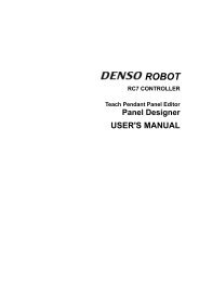
Adjusting the air balance cylinderAdjust the air pressure by using the air regulator so that the end-effector plus payloadchucked by the end-effector will balance with gravity.For details, refer to the graphs below <strong>and</strong> the SETTING-UP MANUAL, Section 5.3,"Adjusting the air pressure balance of the Z-axis, [F1 Arm]—[F12 Maint.]—[F4Adj.Z.Bal]."<strong>HM</strong>-40***G <strong>HM</strong>-40***G series siries (10 (10kg kg payload payload type) type)GGG<strong>HM</strong>-4A***G <strong>HM</strong>-4A***G series siries (20 (20kg kg payload payload type) type)GGGNote: This graph shows only a guideline.Air Pressure <strong>Guide</strong>line25
1.5 Installing the Flange Kit (Option)The flange kit consists of a flange, fixing bolt, <strong>and</strong> setscrew. Install the flange to theT-axis shaft.Robot model Bolt & screw Fixing torqueFor 10 kg payloadFixing bolt (M8) 35±6 NmSetscrew (M5) 1.5±0.15 NmFor 20 kg payloadFixing bolt (M10) 70±13 NmSetscrew (M5) 1.5±0.15 NmCaution: (1) After moving the Z-axis shaft to the upper end, install the flange.(2) The setscrew is only for positioning. Never use it for h<strong>and</strong> fixing.Installing the Flange Kit (<strong>HM</strong>/<strong>HM</strong>S-G)1.6 Engineering-design Notes for Robot H<strong>and</strong>sRefer to the GENERAL INFORMATION ABOUT ROBOT for <strong>HM</strong>-G SERIES, Chapter 3,Section 3.6 "Engineering-design Notes for Robot H<strong>and</strong>s"26
1.7 Moving Each Axis with Motor Power OFF in EmergencyStopThe table below shows which axes have a brake in the <strong>HM</strong>-G series of robot units <strong>and</strong>how to release the brake.Warning:(1) Performing the brake release operation unexpectedly drops orraises the Z-axis. Make sure beforeh<strong>and</strong> that the releaseoperation will not cause bodily injuries or equipmentdamages.(2) When moving the 3rd axis (Z-axis), be careful not to let yourfingers get caught in the geared part of the rack.Robot unit type Axes with brake How to release brakeExceptUL-ListedonesUL-Listed3rd axis (Z)1st axis (J1)2nd axis (J2)3rd axis (Z)With the teach pendant or mini-pendantAccess: [F2 Arm]—[F12 Maint.]—[F3 Brake.] on the teach pendantNote: For details, refer to the SETTING-UP MANUAL, Chapter 5"Comm<strong>and</strong>s Assigned to Function Keys of the TeachPendant" <strong>and</strong> Chapter 6 "Using the Mini-Pendant."When the controller power is ON, holding down the brake releaseswitch releases the brakes of all axes.Note: On UL-Listed robot units, the teach pendant ormini-pendant cannot release the brakes.27
The table below shows how to move each axis with the motor power being OFF whenthe robot is in an emergency stop.Moving the axes in an emergency stopAxis Robot units except UL-Listed ones UL-Listed robot unit1st axis (J1)2nd axis (J2)3rd axis (Z)Move the robot arm by h<strong>and</strong>.(1) Reset the emergency stop state as follows.If the emergency stop has been triggered by the teachpendant or mini-pendant, turn the Emergency stopbutton on the pendant clockwise; if it has beentriggered by the equipment, restore the emergencystop switch to the short-circuited state.(2) Release the brakes with the teach pendant ormini-pendant <strong>and</strong> then move the target axis by h<strong>and</strong>.Move the target axis by h<strong>and</strong>while holding down the brakerelease switch.4th axis (T) Turn the axis by h<strong>and</strong>. Turn the axis by h<strong>and</strong>.Caution: When moving the robot by h<strong>and</strong>, hold by a part other than the plastic cover.28
1.8 Locking Out the Power SwitchStep 1Lock out the power switch during maintenance <strong>and</strong> inspection jobs using acommercially available padlock, according to the following procedure.Check that the power switch of the robot controller is turned OFF.Step 2 Remove the lockout bar provided on the robot controller.Step 3 Put the lockout bar on the upper side of the power switch.Step 4 Padlock the lockout bar.29
Chapter 2 Customizing Your Robot2.1 What Is Customization?You may customize your robot by modifying or setting the following:- Software motion limits for defining the motion space- Mechanical ends for defining the restricted space- Control set of motion optimization- Robot installation conditionsYou are recommended to define new motion space <strong>and</strong> restricted space in order toprevent interference with other devices or entanglement of the h<strong>and</strong>'s wiring <strong>and</strong>piping.WARNING:Always set the software motion limits <strong>and</strong> mechanical ends so that the motion spacewill be within the restricted space. Otherwise, the robot will bump the mechanical stops,causing serious accidents.30
2.2 Modifying Software Motion Limits to Define New MotionSpace2.2.1 What Is a Software Motion Limit?A limit to the operation range of the robot defined by software is called a softwaremotion limit. Software motion limits become valid after CAL of the robot has beencompleted <strong>and</strong> the robot has entered the range set by the limits.A mechanical motion limit is called a mechanical end <strong>and</strong> set by a mechanical stop. Toprevent the robot from striking against a mechanical stop, each software motion limit isset slightly in front of the mechanical end as shown below.If the robot reaches a software motion limit during manual or automatic operation, anerror message will be displayed (error code starting from 607x where x represents theaxis number) <strong>and</strong> the robot will come to a stop. The power to the motor will be alsoturned OFF if the robot is in automatic operation.Each of all axes is assigned a software motion limit in both the positive <strong>and</strong> negativedirection of the operation range. The software motion limit in the positive direction iscalled the positive-direction software motion limit <strong>and</strong> that in the negative direction iscalled the negative-direction software motion limit.Note: Software motion limits are not functions in accordance with safetyst<strong>and</strong>ards.Motion rangeSoftware motion limitMechanical endRestricted rangeNLIM (Negative-directionsoftware motion limit)PLIM (Positive-directionsoftware motion limit)Software Motion Limits <strong>and</strong> Mechanical Ends31
2.2.2 Software Motion Limits (Factory defaults)The table below lists the factory defaults of software motion limits.(1) <strong>HM</strong>-G; St<strong>and</strong>ard typeRobot type<strong>HM</strong>-4***2G<strong>HM</strong>-4***2G-ULSt<strong>and</strong>ard type<strong>HM</strong>-4***3G<strong>HM</strong>-4***3G-UL<strong>HM</strong>-4***4G<strong>HM</strong>-4***4G-UL3rd-axis (Z-axis) stroke 200 mm 300 mm 400 mm1st axis2nd axis3rd axis4th axisPositivedirectionNegativedirectionPositivedirectionNegativedirectionPositivedirectionNegativedirectionPositivedirectionNegativedirection165°-165°147° (<strong>HM</strong>-4*60*E: 143°)-147° (<strong>HM</strong>-4*60*E: -143°)350 mm 350 mm 350 mm150 mm 50 mm -50 mm360º-360º(2) <strong>HM</strong>-G-W; Dust- & splash-proof typeRobot typeDust- & splash-proof type<strong>HM</strong>-4***2G-W <strong>HM</strong>-4***3G-W <strong>HM</strong>-4***4G-W3rd-axis (Z-axis) stroke 200 mm 300 mm 400 mm1st axis2nd axis3rd axis4th axisPositivedirectionNegativedirectionPositivedirectionNegativedirectionPositivedirectionNegativedirectionPositivedirectionNegativedirection165°-165°147° (<strong>HM</strong>-4*60*E-W: 140°, <strong>HM</strong>-4*70*E-W: 146°)-147° (<strong>HM</strong>-4*60*E-W: -140°, <strong>HM</strong>-4*70*E-W: -146°)310 mm 310 mm 310 mm110 mm 10 mm -90 mm360°-360°32
(3) <strong>HM</strong>S-4*70*G; Overhead-mount type (Overall arm length 700 mm)Robot typeSt<strong>and</strong>ard type<strong>HM</strong>S-4*702G <strong>HM</strong>S-4*703G <strong>HM</strong>S-4*704G <strong>HM</strong>S-4*702G-WDust- & splash-proof type<strong>HM</strong>S-4*703G <strong>HM</strong>S-4*704G-W -W3rd-axis (Z-axis) stroke 200 mm 300 mm 400 mm 200 mm 300 mm 400 mm1st axis2nd axis3rd axis4th axisPositivedirectionNegativedirectionPositivedirectionNegativedirectionPositivedirectionNegativedirectionPositivedirectionNegativedirection165° 165°-165° -165°145° 142°-145° -142°-436 mm -456 mm -456 mm -496 mm -496 mm -496 mm-656 mm -756 mm -856 mm -696 mm -796 mm -896 mm360°-360°(4) <strong>HM</strong>S-4*85*G; Overhead-mount type (Overall arm length 850 mm)Robot typeSt<strong>and</strong>ard type<strong>HM</strong>S-4*852G <strong>HM</strong>S-4*853G <strong>HM</strong>S-4*854G <strong>HM</strong>S-4*852G-WDust- & splash-proof type<strong>HM</strong>S-4*853G <strong>HM</strong>S-4*854G-W -W3rd-axis (Z-axis) stroke 200 mm 300 mm 400 mm 200 mm 300 mm 400 mm1st axis2nd axis3rd axis4th axisPositivedirectionNegativedirectionPositivedirectionNegativedirectionPositivedirectionNegativedirectionPositivedirectionNegativedirection165° 165°-165° -165°142° 142°-142° -142°-436 mm -456 mm -456 mm -496 mm -496 mm -496 mm-656 mm -756 mm -856 mm -696 mm -796 mm -896 mm360°-360°33
2.2.3 Changing Software Motion LimitsIf the robot interferes with other devices or the air piping <strong>and</strong> wiring of the h<strong>and</strong> becometaut as the robot arm moves, then change the software motion limits to make themotion space smaller as shown below.Caution: When changing software motion limits, always take into accountthat the robot arm will move within the range specified by the initialsoftware motion limits.Motion range(after change)Motion range(before change)Software motion limitMechanical endRestricted rangeOther devicePositive-directionsoftware motionlimit (1st axis)Negative-directionsoftware motion limit(1st axis) (155º)Changing Software Motion Limits34
2.2.4 Precautions When Changing the Software Motion Limits(1) Confirm the motion space of the robot unit in the actual working environment.(2) When setting the software motion limits, be careful with the units.(3) Specifying too small motion space may cause the robot unit to seem immovable.2.2.5 Procedure for Changing the Software Motion LimitsDescribed below is the procedure for changing the software motion limits.Step 1 Turn the power switch of the robot controller ON.Step 2 Set the mode selector switch of the teach pendant to MANUAL.Step 3 Press [F2 Arm] on the top screen of the teach pendant.F2The Current Robot Position window appears as shown in Step 4.35
Step 4 Press the SHIFT key <strong>and</strong> then press [F12 Maint.].F12The <strong>Maintenance</strong> Functions (Arm) window will appear.Step 5 In the <strong>Maintenance</strong> Functions (Arm) window, press [F1 M Space].The Motion Space window will appear as shown below.Select the item to be modified, then press [F5 Change].F536
Step 6 The numeric keypad will appear as shown below.Enter a desired value using the numeric keys, then press OK.Step 7 The new value will be set on the line of the item selected in the Motion Spacewindow.If two or more items must be changed, repeat Steps 6 <strong>and</strong> 7.Step 8 Press OK in the Motion Space window.Step 9 Turn the robot controller off.Caution: Restarting the controller makes the new motion space settings(software motion limits) effective.37
2.3 Changing Mechanical Ends to Define New Restricted Space2.3.1 What is a Mechanical End Change?In the case of the <strong>HM</strong>-G series, you may change mechanical ends on the 1st through3rd (Z) axes.When the robot leaves the factory, the mechanical ends are set at points 2 to 3outside the default software motion limits. (Refer to Section 2.2.2 "Software MotionLimits (Factory defaults)."Adding mechanical stops to change mechanical ends is called "Mechanical endchange."Regarding to the additional mechanical stopper installation, you may need to prepare<strong>and</strong> install the stopper on your own.Please contact your <strong>DENSO</strong> representative for more details.CAUTIONS IN CHANGING THE MECHANICAL ENDS1. When changing the mechanical ends, design the mechanical stoppers according to yourusage <strong>and</strong> manufacture them.2. After changing the mechanical end, the software motion limits (PLIMs, NLIMs) should bechanged not to interfere the mechanical end at the robot operation.3. When the robot has collided with a mechanical stopper, contact us for inspection <strong>and</strong>repairs before using the robot because the robot may be damaged.Also because the mechanical stopper designed <strong>and</strong> made by the customer may bedamaged, do not reuse the mechanical stopper, but replace it before using the robot.4. The reference drawings described on this manual cannot be covered on the customer’susage conditions sufficiently. Design, manufacture <strong>and</strong> install the mechanical stoppersaccording to your usage conditions.5. The weight addition by the mechanical stoppers may affect the maximum payload.6. The failures caused by the mechanical stoppers shall not be covered by the warranty evenif the robot is under warranty.NOTE: This manual does not include reference diagram of mechanical stoppers.Please contact your <strong>DENSO</strong> representative for more details.38
2.4 Performing CALSET2.4.1 What Is CALSET?Calibrating the relationship between position-related information recognized by therobot controller <strong>and</strong> the actual position of the robot unit is called CALSET.CALSET must be performed when any motor is replaced or when any encoder backupbattery goes dead so that the position-related data retained in the encoder is lost as aresult.After CALSET is completed, the calibrated data of the robot unit will be stored in therobot controller. This data is called CALSET data which differs on each robot.Back up the CALSET data periodically, referring to "Backing Up Projects."39
2.4.2 Preparation for CALSETPress each of the 1st- to 4th-axes against the associated mechanical ends by h<strong>and</strong> toget the actual positions.CALSET requires some space for bringing each axis into contact with the mechanicalend.Caution: (1) When CALSETing, move the axis to be CALSET in the vicinity ofthe mechanical end, release the brake, <strong>and</strong> bring the axis intocontact with the mechanical end. When bringing the 3rd axis(Z-axis) into contact with the mechanical end, be careful not to letyour fingers get caught in the geared part of the rack.(2) After CALSET, confirm in the manual mode that each axis stopsat the software motion limit before coming into contact with themechanical end.(3) In automatic operation, start to run the robot at low speed.Ensuring safety, gradually increase the speed. It makesadjustment easy.(4) Position-related data in some programs made before CALSETmay vary somewhat after CALSET.NOTE: When CALSETing the 4th axis of the dust- & splash-proof type, you need topull down the lower bellows for setting the CALSET bolt.40
What is a CALSET position?The limit position of an axis to be CALSET is called a CALSET position. Each axis hasa mechanical end in each of the positive <strong>and</strong> negative directions. The CALSET to becarried out before shipment uses mechanical ends shown below as CALSET positions.(2) CALSET position (<strong>HM</strong>/<strong>HM</strong>S-G series)Mounting CALSET bolts on the 4th axis: To CALSET the 4th axis, you need tomount a CALSET bolt on the axis. As illustrated below, the CALSET bolt is built in therobot unit, so remove it <strong>and</strong> set it up into the specified position. After completion ofCALSET, put it back into place.Location1st axis2nd axis3rd axis4th axisTurning end in the positive direction (counterclockwise end when viewed from the top)Turning end in the negative direction (clockwise end when viewed from the top)Upper end (in the positive direction)Turning end in the positive direction (counterclockwise end when viewed from the top)<strong>HM</strong>-G series<strong>HM</strong>S-G seriesExternalappearanceFor <strong>HM</strong>-G seriesNotes for 4th axis CALSET(1) Remove the CALSET bolt from the robot <strong>and</strong> setit as shown in right figures.(2) Rotate the 4th axis shaft to the CALSET positionby moving the stopper with h<strong>and</strong>.Caution: Never push with too large torque.Pushing torque: 0.5Nm or lessFor <strong>HM</strong>-G-W series(3) In case of the dust- & splash-proof type, perform4th-axis CALSET after removing the lowerbellows.CALSET Positions at Shipment (<strong>HM</strong>/<strong>HM</strong>S-G series)41
2.4.3 Performing CALSET[ 1 ] CALSET of a Single AxisCALSETing a specified single axis only is called single-axis CALSET.Perform single-axis CALSET if the motor of an axis is replaced so that the axis must beCALSET, or if some axes cannot be moved to the CALSET positions (mechanical stoppositions) at any given time because of interference between the robot unit <strong>and</strong> itssurrounding facilities.Described below is the procedure to perform single-axis CALSET.For the UL-Listed robot units, brake releasing is required in CALSETing the 1st, 2nd,<strong>and</strong> 3rd axes each; for other models, it is required only in CALSETing the 3rd axis.Caution: When moving the robot by h<strong>and</strong>, hold by a part other than the plastic cover.Step 1 Move the axis to be CALSET to the mechanical end position.• Brake releasing on UL-Listed robot unitsOn the UL-Listed robot units, when the brake release switch is being pressed,the brakes of all axes are released.With the brake release switch being pressed, move the axis to be CALSET byh<strong>and</strong> to bring it into contact with the mechanical end in the CALSET position.At that time, be careful not to let your fingers get caught in the geared part ofthe rack. After that, skip to Step 10.Step 2 On the top screen of the teach pendant, press [F2 Arm].Step 3 Press the SHIFT key <strong>and</strong> [F12 Maint.].The <strong>Maintenance</strong> Functions (Arm) window appears as shown below.F3Press [F3 Brake.].42
Step 4 The Brake release setting window appears as shown below.Step 5 Select "Brake released."Step 6 Confirm that there is no danger even if the arm falls as a result of the brakebeing released.Then press OK.43
Step 7 The system message appears asking you whether you want to change the brakesettings.Press OK.Step 8 The system message appears informing that the brake is released.Press OK.Step 9 Press the axis to be CALSET against the mechanical end in the CALSETposition by h<strong>and</strong>.Caution: When bringing the 3rd axis (Z-axis) into contact with the mechanical end,be careful not to let your fingers get caught in the geared part of the rack.44
Step 10 Press [F6 CALSET.].The Set CALSET window appears as shown below.Step 11 Press the axis number to be CALSET to turn it on (green). For other axes thatare not to be CALSET, turn it off (black).Press OK.45
Step 12 The system message appears asking whether you want to carry out CALSET.Press OK.Step 13 The system message appears informing that CALSET is successfully completed.Press OK.Step 14 Press the ROBOT STOP button.The robot brake becomes activated.Step 15 Turn the ROBOT STOP button to cancel robot stop.Step 16 Press the MOTOR key to turn the motor ON.Caution: A "motor lock overload" error may occur just after the power to themotor is turned ON. In this case, try to turn ON the power to the motorseveral times, or release the brake, move the axis a little in theopposite direction of the mechanical end, <strong>and</strong> turn ON the power to themotor again.46
Step 17 Move the CALSET axis in the opposite direction from the mechanical end bymanual operation from the teach pendant.The single-axis CALSET of the specified axis is completed.[ 2 ] CALSET of All AxesThe CALSET of all axes is called all-axis CALSET.The procedure is the same as that for single-axis CALSET except that you shouldselect all axes in Step 11. For detailed procedure, see “[ 1 ] CALSET of a Single Axis.”47
2.5 Setting Control Set of Motion OptimizationThe optimum speed or acceleration will vary depending upon the payload <strong>and</strong> center ofgravity of the h<strong>and</strong> <strong>and</strong>/or workpiece that are to be set at the end of the robot flange.Set the payload <strong>and</strong> center of gravity position of the h<strong>and</strong> or workpiece <strong>and</strong> the controlset of motion optimization according to the payload <strong>and</strong> the robot posture.The mass of payload is a total mass of a h<strong>and</strong> <strong>and</strong> workpiece, expressed in gram.For further information, see the PROGRAMMER'S MANUAL (I), Section 4.7, "Settingthe Master Control Parameters in User Preferences." For the setting procedure, referto the SETTING-UP MANUAL, Section 2.8 "Setting the Master Control Parameters ofthe Payload, Center of Gravity, <strong>and</strong> Control Set of Motion Optimization."2.6 Setting Robot <strong>Installation</strong> ConditionsDepending on whether the robot is floor-mounted or overhead-mounted, the optimumoperating conditions differ.However, as for horizontal articulated type; the <strong>HM</strong>-G series (floor-mount type) <strong>and</strong><strong>HM</strong>S-G series (overhead-mount type), the installation conditions are preset at thefactory. You do not need to change the factory default of the installation settings.48
Chapter 3 <strong>Maintenance</strong> <strong>and</strong> Inspection3.1 <strong>Maintenance</strong> & Inspection Intervals <strong>and</strong> PurposesThe table below lists the intervals <strong>and</strong> purposes of maintenance & inspection requiredfor your robot.<strong>Maintenance</strong> & Inspection Intervals <strong>and</strong> PurposesNo. Intervals What to do: Needed:1 Daily beforestartingoperationsInspection jobs specifiedin Section 3.2.2 Quarterly Inspection jobs specifiedin Section 3.3.3 Semiyearly Inspection jobs specifiedin Section 3.4.4 Biennial Replacement of backupbatteries specified inSection 3.5.To use your robot safely.To maintain the precision of the robot <strong>and</strong> to preventfailures caused by overheat of the robot controller.To check the rotary sections <strong>and</strong> slideways of therobot <strong>and</strong> its controller for wear, preventing seizure,breakage, <strong>and</strong> other serious failures that could resultfrom wear.To retain the position data stored in the electronicabsolute encoders built in the robot unit <strong>and</strong> therobot-specific data (programs, parameters, etc.)stored in the internal memory of the robot controller.To maintain the precision of the robot motion.Caution: <strong>Maintenance</strong> <strong>and</strong> inspection must be carried out by a trainedworker who possesses the ability to perform these tasks safely.Before performing maintenance <strong>and</strong> inspection jobs, read theSAFETY PRECAUTIONS, "4. Precautions while Robot isRunning" <strong>and</strong> "5. Daily <strong>and</strong> Periodical Inspections."49
3.2 Daily Inspections3.2.1 Check ItemsBefore starting operations, check the items listed below every day.Daily Inspections TableNo.Check:ControllerPowerHow to check:CriterionWhat to do:(Note 1)123456Connectors (CN1 toCN10 on the robotcontroller) <strong>and</strong> theirmating partsCables (connected toCN1 to CN10 on therobot controller) <strong>and</strong>robot’s external cablesLCD on the teachpendantPilot lamps on the robotcontrollerCooling fan in the robotcontrollerEMERGENCY STOPbutton on the teachpendant or the minipendantOFFOFFVisuallyVisuallyEngage theNo looseness, parts properlydisengagement or dirt. <strong>and</strong> cleanthem.Free of damage orgouges.ON Visually Properly displayedON Visually Should light.ONON7 Safety door ON891011Brake release switchon the UL-Listed robotunitsBellows (on the Z-axisof dust- & splash-prooftype)Motor ON lamp on theUL-Listed robot unitsRobot unit (Exceptlubrication points)Visually(Note 2)Press theEMERGENCY STOPbutton.Operate the safetydoor switch <strong>and</strong> openthe switch-wiring door.Should work properly.The robot shouldcome to anemergency stop.The robot shouldcome to anemergency stop.Repair orreplace.Repair orreplace.Repair orreplace.Repair orreplace.Repair orreplace.Inspect <strong>and</strong>repair.OFF Check for looseness. No looseness. Tighten up.OFF Visually No breakage.ONVisuallyIt should light whenthe motor is ON.OFF Visually No grease leakInspect <strong>and</strong>repair.Inspect <strong>and</strong>repair.Wipe offgreaseNote 1 Some repair <strong>and</strong> replacement operations shown in "What to do:" columnmay involve special jobs. Contact our Robot Service Section.Note 2 The normal operation of the cooling fan is as shown on the next page.50
Normal Operation of Cooling Fan3.3 Quarterly Inspections3.3.1 Check Items <strong>and</strong> LubricationCheck the items listed below every three months.Quarterly Inspections TableNo.Check:ControllerPowerHow to check: Criterion What to do:12Robot basemounting boltsCooling fan filtersin the robotcontrollerOFFMeasure thetighteningtorque with atorque wrench.No looseness.Specified torque:128 ±20 NmTighten the bolts to thespecified torque.OFF Visually No dust or dirt. Clean the cooling fanfilters. (Refer to Section3.3.2.)3.3.2 Cleaning the Cooling Fan Filters in the Robot ControllerFor the cleaning procedures of the air intake filter, refer to the RC7M CONTROLLERMANUAL, Section 6.4 "Cleaning the Air Intake Filter."51
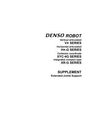
3.4 Semiyearly Inspections3.4.1 LubricationApply the specified grease to the whole Z-axis shaft as shown below every six months.Lubrication Points <strong>and</strong> Lubricants (<strong>HM</strong>/<strong>HM</strong>S-G series)No. Lubrication points Lubricant type123LubricantamountZ-axis shaft Epinoc AP1 2 to 3 ccZ-axis rack Epinoc AP1 2 to 3 ccZ-axis air balance cylindershaftEpinoc AP12 to 3 ccRemarksApply the grease to the whole Z-axisshaft.Apply the grease to the rack <strong>and</strong>gear of the Z-axis shaft.Apply the grease to the wholecylinder shaft.2Z-axis rackRailCross section of Z-axis rackRail⇒End-of-arm sideTooth surface3Z-axis air balancecylinder shaft1Z-axis shaftNOTE: When applying grease to the dust- & splash-proof type, you need to pulldown the upper bellow on the Z-axis shaft.52
3.5 Biennial Inspections3.5.1 Battery Replacement <strong>and</strong> Belt InspectionReplace the two types of backup batteries listed below <strong>and</strong> inspect the timing beltsevery two years.Please contact your <strong>DENSO</strong> representative to inspect timing belts <strong>and</strong> to adjust them.Caution:(1) The battery used in this device may present a risk of fire orchemical burn if mistreated. Do not recharge, disassemble,heat above 100°C (212°F), or incinerate.(2) Dispose of used battery promptly. Keep away from children.Do not disassemble <strong>and</strong> do not dispose of in fire.Types of Backup BatteriesBattery type Used to: Located: Refer to:1 Encoder backup batteryBack up the position dataof the servomotorencoder.In the robot unitSection3.5.22 Memory backup batteryBack up programs,parameters, <strong>and</strong> CALdata.In the robotcontrollerSection3.5.3The position data of the encoder contained in the servomotor is stored in the internalmemory of the encoder.Programs, parameters, CAL data, etc. are stored in the internal memory of the robotcontroller.The backup battery for each memory retains the above data, while the power to therobot controller is turned OFF. However, these batteries have a limited lifetime <strong>and</strong>must, therefore, be replaced regularly.Caution:Without replacing the backup batteries, important robot-specificdata stored in each memory will be lost.53
3.5.2 Replacing the Encoder Backup BatteryReplace the encoder backup battery according to the procedure given below.STEP 1 Prepare two new backup batteries for replacement.STEP 2 Turn the controller power OFF.STEP 3Remove the cover from the robot unit.Four hex. socket-head bolts (M3x8)CoverNOTE: On the dust- & splash-proof type, the cover has a packing forsealing. Take care not to lose it.54
STEP 4 Disconnect the old battery (1st one) from the battery board <strong>and</strong> thenremove it from the holder.Old backup battery(1st one)ConnectorHolderBattery boardSTEP 5Connect a new battery (1st one) to the battery board from which youhave disconnected the old one in Step 4, <strong>and</strong> then load it into theholder.New backup battery(1st one)Battery boardNOTE: Do not disconnect both of the current batteries at the sametime. Doing so will lose the encoder positional data.STEP 6 Disconnect the remaining old battery (2nd one) from the battery board<strong>and</strong> then remove it from the holder.Old backup battery(2nd one)ConnectorBattery boardHolder55
STEP 7Connect a new battery (2nd one) to the battery board from which youhave disconnected the old one in Step 6, <strong>and</strong> then load it into theholder.New backup battery(2nd one)Battery boardNOTE: Be sure to replace both of two batteries with new ones at onetime. Otherwise, the battery service life will become short.STEP 8 Install the cover to the robot unit.NOTE: On the dust- & splash-proof type, the cover has a packing forsealing. Take care not to lose or pinch it.Tightening toqueHex. socket-head bolt (M3x8): 1.6±0.3 N•m56
3.5.3 Replacing the Memory Backup BatteryFor the replacing procedures of the memory backup battery, refer to the RC7MCONTROLLER MANUAL, Section 6.5 "Replacing the Memory Backup battery."3.5.4 Setting the Next Battery Replacement DateAfter replacing the memory backup battery, set the next battery replacement date fromthe teach pendant, according to the following procedure.Check that the system clock of the robot controller shows the correct date beforeh<strong>and</strong>.If it is incorrect, the next replacement date will also become incorrect.STEP 1 On the top screen of the teach pendant, press [F6 Set].The Settings (Main) window appears.STEP 2 Press [F6 Maint.] in the Settings (Main) window.The <strong>Maintenance</strong> menu appears.STEP 3 Press [F4 Battery] in the <strong>Maintenance</strong> menu.The Next Battery Replacement Date window appears.In the top of the window, the current setting is displayed.The date entry areas show the default replacement date that is two yearslater the current data at which you open this window, assuming that thebattery service life is two years.STEP 4 Press OK.NOTE: If you do not want to change the replacement date, press Cancel.The message "Are you sure you want to set the next battery replacementdate?" appears.STEP 5 Press OK.The screen returns to the Settings (Main) window.57
3.6 Supplies for <strong>Maintenance</strong>The table below lists the supplies for maintenance.Supplies for <strong>Maintenance</strong>No Name Part No. Remarks1 Grease 410971-0040 2.5 kg can2 Grease 410971-0050 16 kg canEpinoc Ap-l3 Encoder backup battery set 410679-0010 A set of two batteries (HS-E17500)4 Air filter set410053-0100 For st<strong>and</strong>ard type of controllers (FS-1705W)410053-0110 For global type of controllers (FS-1705)5 Memory backup battery 410076-0261 For RC7M controller6 Fuse (1.3A) 410054-0230 For LM13 for controller I/O7 Fuse (3.2A) 410054-0270 For LM32 for controller I/O8 IC for output (NPN) 410077-0010 IC (M54522P) for controller output9 IC for output (PNP) 410077-0020 IC (M54564P) for controller output3.7 Replacing Fuses <strong>and</strong> Output ICsFor the replacing procedures of the fuses <strong>and</strong> output ICs, refer to the RC7MCONTROLLER MANUAL, Section 6.6 "Replacing Fuses <strong>and</strong> Output ICs."58
3.8 Checking the Odometer <strong>and</strong> Trip MeterYou may check the odometer <strong>and</strong> trip meter which count traversed distance of eachaxis in the Odometer window of the teach pendant.The access to the Odometer window is [F6 Set]—[F6 Maint.]—[F5 Odometer].The Odometer window shows the following items:[Odometer] Shows the total distance of each axis traversed after the robot leaves thefactory. You cannot reset the odometer.[Trip meter] Shows the distance of each axis traversed after you reset the trip meterto zero. You can reset the trip meter by pressing [F6 Reset] in theOdometer window <strong>and</strong> following the guidance shown on the screen.3.8.1 Displaying the Odometer <strong>and</strong> Trip MeterSTEP 1 Turn the robot controller ON.STEP 2 On the teach pendant, set the mode switch to the MANUAL position.STEP 3 On the top screen, press [F6 Set].The Settings (Main) window appears as shown below.Press [F6 Maint.].F659
STEP 4 The <strong>Maintenance</strong> menu appears as shown below.F5Press [F5 Odometer].STEP 5 The Odometer window appears as shown below.In the above Odometer window, the J1, J2 <strong>and</strong> J4 are expressed in numberof revolutions <strong>and</strong> J3 in meter.F660
3.8.2 Resetting the Trip Meter to ZeroSTEP 1 Display the Odometer window as shown below.Access: [F6 Set]—[F6 Maint.]—[F5 Odometer] from the top screen.Press [F6 Reset].F6STEP 2 The following message appears.Press the OK button.The trip meter has been reset to zero.61
3.9 Checking the Controller ON-Time <strong>and</strong> the Robot RunningTime <strong>and</strong> Resetting Their User CountersYou may check the robot controller ON-time <strong>and</strong> the robot running time in the Totalhours window of the teach pendant.The Total hours window shows the following items:[Total operation] Shows the gr<strong>and</strong> total of the robot controller ON-time counted afterthe controller leaves the factory.[Total running] Shows the gr<strong>and</strong> total of the robot running time counted after therobot leaves the factory.[Cumu. operation] Shows the total of the robot controller ON-time counted after youreset the user counter to zero.[Cumu. running] Shows the total of the robot running time counted after you resetthe user counter to zero.[Operation] Shows the ON-time of the robot controller counted after it is turnedON this time.[Running] Shows the running time of the robot counted after the robotcontroller is turned ON this time.3.9.1 Displaying the Controller ON-time <strong>and</strong> the Robot Running TimeSTEP 1 Display the <strong>Maintenance</strong> window as shown below.Access: [F6 Set]—[F6 Maint.] from the top screenPress [F1 Total h].F162
STEP 2 The Total hours window appears as shown below.[Total operation] Shows the gr<strong>and</strong> total of the robot controller ON-time counted afterthe controller leaves the factory.[Total running] Shows the gr<strong>and</strong> total of the robot running time counted after therobot leaves the factory.[Cumu. operation] Shows the total of the robot controller ON-time counted after youreset the user counter to zero.[Cumu. running] Shows the total of the robot running time counted after you resetthe user counter to zero.[Operation] Shows the ON-time of the robot controller counted after it is turnedON this time.[Running] Shows the running time of the robot counted after the robotcontroller is turned ON this time.63
3.9.2 Resetting the User Counters of the Controller ON-Time <strong>and</strong> theRobot Running TimeSTEP 1 Display the Total hours window as shown below.Access: [F6 Set]—[F6 Maint.]—[F1 Total h] from the top screenTo reset the user counter of the controller ON-time (Cumu.operation), forexample, press [F4 Cumu. o].F4STEP 2 The following system message appears.Press the OK button.64
STEP 3The user counter of the controller ON-time has been reset to zero as shownbelow.65
3.10 Backing up ProjectsYou should back up project data periodically in WINCAPSIII in order to recover therobot controller smoothly after loss of project data due to unexpected accidents suchas expired service life of memory backup batteries.Be sure to back up project data <strong>and</strong> preserve it, in particular:- at the time of purchase- after performing CALSET- after changing RANG values- after replacement of a motor<strong>DENSO</strong> preserves arm data configured at the time of shipment for 10 years. If yourarm data is lost, contact your <strong>DENSO</strong> representative.NoteArm data refers to CALSET <strong>and</strong> RANG values in project data, which isunique to individual robots <strong>and</strong> determines the position of each joint.3.10.1 Back up project dataUse WINCAPSIII to back up project data.When a project has been created in WINCAPSIIIReceive all data from the controller <strong>and</strong> preserve it.When creating a new project to preserve backup dataFollow the procedure given below.STEP 1 Create a new project in WINCAPSIII.66
STEP 2 Choose "Get information from the controller for creating a new project."STEP 3 Following the project wizard, enter the IP address <strong>and</strong> the desired backupfile name.STEP 4Select "Receive data from the controller after creating the project."STEP 5Close the project.67
3.10.2 Transfer arm dataWhen WINCAPSIII exchanges project data with the robot controller, arm data uniqueto individual robots can be transferred only from the robot controller to WINCAPSIII,but it cannot from WINCAPSIII to the robot controller. This is to protect arm data in therobot controller from being overwritten accidentally.To transfer arm data from WINCAPSIII to the robot controller, use the followingprocedure.STEP 1 Loading the arm data (***.wam) into the WINCAPSIII projectThis step is necessary when only arm data is supplied by <strong>DENSO</strong>. Whenproject data has been backed up, open the project data in WINCAPSIII <strong>and</strong>proceed to STEP 2.Start WINCAPSIII, log on as a Programmer, <strong>and</strong> create a project suitable foryour robot model.Choose Tool | Arm parameters to display the Arm Parameter window.Press Load <strong>and</strong> select the arm data (***.wam) to load.STEP 2 Configuring communication options for transfer of arm data fromWINCAPSIII to the robot controllerChoose Tool | Option | Communication tab. Select "Data send setting:CALSET data" <strong>and</strong> press OK.ATTENTION: During ordinary operations, the "Data send setting:CALSET data" should be deselected. If it is selected,creating a new project <strong>and</strong> transferring arm parametersoverwrites the CALSET-related data in the robot controllerwith the transferred data, causing errors in teachingpositions.68
STEP 3 Transferring arm data to the robot controllerChoose Connect | Transfer data to display the Transfer data window.Select Parameters | Arm parameters <strong>and</strong> Configuration | CALSET, thenpress Send.Upon completion of transfer of the CALSET-related arm data, restart therobot controller.69
Horizontal Articulated Robot<strong>HM</strong>-G SERIESINSTALLATION & MAINTENANCE GUIDEFirst Edition July 2005Ninth Edition April 2011Tenth Edition October 2011<strong>DENSO</strong> WAVE INCORPORATED10N**CThe purpose of this manual is to provide accurate information in the h<strong>and</strong>ling <strong>and</strong> operating of therobot. Please feel free to send your comments regarding any errors or omissions you may havefound, or any suggestions you may have for generally improving the manual.In no event will <strong>DENSO</strong> WAVE INCORPORATED be liable for any direct or indirect damagesresulting from the application of the information in this manual.