vm-g series installation & maintenance guide - DENSO Robotics
vm-g series installation & maintenance guide - DENSO Robotics
vm-g series installation & maintenance guide - DENSO Robotics

You also want an ePaper? Increase the reach of your titles
YUMPU automatically turns print PDFs into web optimized ePapers that Google loves.
CHCF/HSC – HEALTH BENEFITS 2006 PAGE 1(At the end of the interview:)I would like to confirm your name and address so we may mail you the survey report, which should be sent out inNovember of this year.VERIFY INFORMATION AND ENTER BELOW:1 NAME:2 TITLE:3 COMPANY:4 STREET ADDRESS:5 CITY, STATE:6 ZIP CODE (Zip+4):7 TELEPHONE NUMBER: (___ ___ ___)___ ___ ___ - ___ ___ ___ ___Hello. May I please speak with your benefits manager?California Employer Health Benefits, 2006IF THEY DO NOT HAVE A BENEFITS MANAGER, SAY: May I please speak with the person in charge of humanresources?We are conducting a survey about job-based health benefits with the California HealthCare Foundation, an independenthealth care philanthropy. We would value your input for the study. In return for your participation, we will send you a freecopy of the full report later this year. This report will contain the latest information on health insurance premiums, howmuch employees pay for their health care, and many other topics. Benefits managers can use it as a reference tool. Theinformation you provide will be kept strictly confidential, and nobody will contact you as a result of this survey. We maileda letter explaining the survey, outlining some of the information we will be collecting.If respondent would like verification of the survey, the contact is Heidi Whitmore: (763) 478-6725.If Respondent refuses to complete survey ask: Does your company offer health benefits to youremployees? Then use the notation RF-NO PLAN, RF-HAVE PLAN, RF-NO ANSWER.
Copyright © <strong>DENSO</strong> WAVE INCORPORATED, 2005-2011All rights reserved. No part of this publication may be reproduced in any form or by any meanswithout permission in writing from the publisher.Specifications are subject to change without prior notice.All products and company names mentioned are trademarks or registered trademarks of theirrespective holders
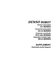
PrefaceThank you for purchasing this high-speed, high-accuracy assembly robot.Before operating your robot, read this manual carefully to safely get the maximum benefit from your robotin your assembling operations.Robot <strong>series</strong> and/or models covered by this manualSeriesFloor-mountModelOverhead-mountRemarks(Max. reach nickname)VM-G(Medium-sized, vertical articulated)VM-6083GVM-60B1GSame as left.Same as left.(VM1000)(VM1300)NOTE 1: Model names listed above apply to the models of robot systems. The model names of robotunits are followed by M. If the robot system model is VM-6083G, for example, the robot unit model isVM-6083D/GM.ImportantTo ensure operator safety, be sure to read the precautions and instructions in "SAFETY PRECAUTIONS".
How this book is organizedThis book is just one part of the robot documentation set. This book consists of SAFETY PRECAUTIONS,chapters one through three.Chapter 1 Installing Robot ComponentsProvides information about physical site planning, <strong>installation</strong> procedures, and engineering-design notesfor hands.Chapter 2 Customizing Your RobotDescribes how to customize your robot--defining the software motion space and restricted space,CALSETing, and setting control set of motion optimization.Chapter 3 Maintenance and InspectionDescribes the regular <strong>maintenance</strong> and inspections necessary for maintaining the performance andfunctions of your robot.
Chapter 3 Maintenance and Inspection........................................................................................................................ 703.1 Maintenance & Inspection Intervals and Purposes ............................................................................................. 703.1.1 Precautions for <strong>installation</strong> and <strong>maintenance</strong> of robots for cleanroom use .................................................. 713.2 Daily Inspections................................................................................................................................................. 723.2.1 Check Items.................................................................................................................................................. 723.3 Quarterly Inspections .......................................................................................................................................... 733.3.1 Check Items.................................................................................................................................................. 733.3.2 Cleaning the Cooling Fan Filters in the Robot Controller............................................................................ 733.4 Biennial Inspections ............................................................................................................................................ 743.4.1 Battery Replacement and Belt Inspection..................................................................................................... 743.4.2 Replacing the Encoder Backup Battery........................................................................................................ 753.4.3 Replacing the Memory Backup Battery ....................................................................................................... 813.4.4 Setting the Next Battery Replacement Date ................................................................................................. 813.5 Supplies and Tools for Maintenance ................................................................................................................... 823.6 Replacing Fuses and Output ICs ......................................................................................................................... 823.7 Checking the Odometer and Trip Meter.............................................................................................................. 833.7.1 Displaying the Odometer, Trip Meter, and Oil Change Intervals ................................................................. 833.7.2 Resetting the Trip Meter to Zero .................................................................................................................. 853.8 Checking the Controller ON-Time and the Robot Running Time and Resetting Their User Counters............... 863.8.1 Displaying the Controller ON-time and the Robot Running Time ............................................................... 863.8.2 Resetting the User Counters of the Controller ON-Time and the Robot Running Time .............................. 883.9 Resetting Encoders.............................................................................................................................................. 903.10 Backing up Projects............................................................................................................................................. 913.10.1 Back up project data ..................................................................................................................................... 913.10.2 Transfer arm data.......................................................................................................................................... 93
Chapter 1 Installing Robot Components1.1 Preparing a Proper Environment for InstallationBefore installing the robot unit and robot controller, confirm that the operatingenvironment is in conformity with each item of SAFETY PRECAUTIONS, "InstallationPrecautions". Also, take proper measures to protect the components from vibration.In an inappropriate environment, the robot will not operate to its full capacity orperformance, components may not last long, and unexpected failure may result.1.1.1 Ambient Temperature and Humidity1.1.2 VibrationKeep the ambient temperature between 0C and 40C during operation.Keep the ambient humidity at 90% or below to prevent dew condensation.Do not install the robot in an environment where it will be exposed to excessivevibration or impact.Caution: When the excessive vibration is added to the robot unit at power-offduring transportation, ERROR 2AF1 (Encoder reference positionerror) may occur.If the ERROR 2AF1 occurs when turning the robot controller ON atfirst after purchasing the robot, refer to the “ERROR CODETABLES” or contact our Robot Service Section.1.1.3 Connecting the Robot Unit and Robot ControllerBefore delivery, the robot unit and the robot controller are configured as a set. If youpurchase two or more robot systems, take care not to mistake each set whenconnecting robot units and controllers.Caution: The robot unit and robot controller in a set are given the same serialnumber.1.1.4 Installation Environment of the Robot UnitThe <strong>installation</strong> requirements for the robot unit are shown on the next page. Prepare ahighly rigid mount by referring to the figure on page 4.Caution Do not electric-weld the equipment including the robot. A largecurrent may flow through the motor encoder or robot controllerresulting in a failure. If electric welding is required, remove therobot unit and the robot controller from the equipmentbeforehand.1
Installation Requirements for the Robot UnitItemFlatness of the mountRigidity of the mountInstallation typeAmbient temperatureHumidityVibrationAltitudeSafe <strong>installation</strong>environmentWorking space, etc.Grounding conditionsEnvironments and Conditions0.1/500 mm (See the upper figure on the next page.)Use steel materials. (See the figure on the next page.)Floor-mount or Overhead-mountDuring operation : 0 to 40CDuring storage and transportation : -10 to 60CDuring operation : 90% or less (No dew condensation allowed.)During storage and transportation : 75% or less (No dew condensationallowed.)During operation : 4.9 m/s 2 (0.5G) or lessDuring storage and transportation : 29.4 m/s 2 (3G) or lessDuring operation: 1,000 m or lessRefer to the SAFETY PRECAUTIONS, 3.1 "Insuring the proper<strong>installation</strong> environment"• Sufficient service space must be available for inspection and disassembly.• Keep wiring space (230 mm or more) behind the robot, and fasten the wiringto the mounting face or beam so that the weight of the cables will not bedirectly applied to the connectors.Functional groundSee the figure on page 21.2
1000 or less20 or more100 100pipe500 or moreCaution (1) When the robot operates at high speed, the robotmount undergoes large reaction forces. The mountmust be rigid enough so that it will not vibrate or bedisplaced due to reaction forces. It is also advisableto mechanically join the robot mount with heavyequipment.(2) Some mounts may produce a resonance sound(howling). If this sound is loud, increase the rigidityof the mount or slightly modify the robot speed.Robot Mount Example for Floor-mountStrutMounting face350 350 20or more100 100 t6.0(square steel pipe)Caution (1) When the robot operates at high speed, the top platestructure undergoes large reaction forces. Designthe vibration-proof mount so that the top plate will notvibrate due to reaction forces. Also design the topplate structure so that it separates from other topplate structures in the equipment.(2) Some mounts may produce a resonance sound(howling). If this sound is loud, increase the rigidity ofthe mount or slightly modify the robot speed.Robot Mount Example for Overhead-mount3
1.2 Mounting the Robot UnitCautionBefore handling or installing the robot unit, be sure to readSAFETY PRECAUTIONS, "Installation Precautions."1.2.1 Transporting the Robot Unit(1) Precautions in transporting the robotThe VM-G <strong>series</strong> weighs approximately 88 kg (193 lbs). Use a crane suitable for therobot weight.Have at least two workers handle this job.Workers should wear helmets, safety shoes, and gloves during transport.CautionPass the hoisting wires through the specified eyebolts asillustrated below. Passing them through other sectionsmay drop the robot unit, resulting in a broken robot orbodily injuries.Do not hold the first arm, elbow, either side of the 2nd arm,2nd-axis cover, or 3rd-axis cover, or apply force to any ofthem.VM-6083G/VM-60B1GWire(Belt sling)Waste clothEyeboltsRobot unitmounting boltsHoisting Points for Transportation (VM-G <strong>series</strong>)4
(2) Transporting the robot unitNo. Procedure Explanatory Illustration1 Before transportation,set the robot in atransport position asshown at right bymanually moving thesecond, third andfourth axes.VM6083G/VM60B1GWhen unpacked first,the robot is in thetransport position, sothis job is not required.Transport Position2 Disconnect the robotcontrol cable, airpiping and user signalcables from the robotunit.When the robot unit isfirst unpacked, this jobis not required.3 As shown at right,mount the eyebolts.AxisAngleFirst axis (J1)0Second axis (J2) -90Third axis (J3) +165Fourth axis (J4) +90 or -90Fifth axis (J5) +90 or -90VM6083G/VM60B1GWhen delivered, therobot unit is packedwith eyeboltsattached, so this job isnot required.Mounting EyeboltsMount two eyeboltsperpendicular to the line of therobot unit.5
No. Procedure Explanatory Illustration4 As shown at right,place a waste cloth onthe second arm andpass the wire throughthe two eyebolts.VM6083G/VM60B1GWire(Belt sling)Waste clothEyeboltsRobotunitmountingboltsHoisting the Robot Unit5 Worker A: Remove thefour bolts whilesupporting the robotunit to prevent it fromgetting overturned.6 Worker B: Operate thecrane and move therobot unit to the targetsite.7 Worker B: Put therobot unit down in thetarget position.Worker A: Temporarilysecure the robot unitwith four bolts.8 Secure the robot unitaccording to theinstructions in Section1.2.2 "Securing theRobot Unit" on thenext page.9 Remove the eyeboltsfrom the robot unit.Caution (1) Before transporting the robot, check that the path to thetarget position is free of obstacles.(2) Before running the robot unit, be sure to remove theeyebolts. Otherwise, the robot arm will strike againstthose eyebolts.6
1.2.2 Securing the Robot Unit(1) Drill four bolt holes (M12) 15-mm deep or more in the robot mount where the robotunit is to be secured, according to the dimensions shown below.ReferenceplaneFrontConnector sideReferenceplane(for mounting M12 bolt)Bolt Positions for Securing the VM-6083G/VM-60B1G(2) Secure keys or pins to the reference planes.NOTE: Be sure to secure keys or pins. They can minimize positional deviationswhen you remove and reinstall the robot unit for <strong>maintenance</strong>.(3) Set the robot unit into place on the robot mount.NOTE: When transporting the robot unit, follow the instructions given in Section1.2.1 "Transporting the Robot Unit."(4) Secure the robot to the mount with four bolts and plain washers.- Bolt: M12 x 40 mm (strength class: 12.9, tightening torque: 128 ±26 Nm)- Plain washer: JIS B 1256 (polished round)7
1.2.3 Overhead-mounting the RobotTo overhead-mount the robot, an overhead-mount frame and suspension jig arerequired. Set up those items, referring to the overhead-mount frame shown below andthe suspension jigs specified on the following pages.Caution (1) Install the robot according to Section 1.2.2 "Securing the RobotUnit" on the previous page. Use bolts of strength class 12.9.(2) Keep a space of 250 mm or larger for wiring behind the robot.Fasten the wiring to the mounting face or beam so that theweight of the cables will not be directly applied to theconnectors.Overhead-mount FrameThe figure below shows an example of overhead-mount frame.StrutMounting face350 350 20or more100 100 t6.0(square steel pipe)Example of Overhead-mount Frame (VM-G <strong>series</strong>)Caution: When the robot is running at high speed, large reaction forces areexerted on the top plate structure. Take proper measures to protectthe top plate from vibration caused by reaction forces. Separate therobot <strong>installation</strong> top plate structure from other top plate structureswithin the equipment.8
VM-6083G/VM-60B1G(1) Overhead-mount Suspension JigsTo mount the robot overhead, five types of jigs--suspension jigs A, B and C, twoholders and two holder stopper plate--are required. The upper figures on this pageshow how to mount suspension jigs A and B, and the lower figure shows how to mountsuspension jig C, holder and holder stopper plates. The reference drawings formounting suspension jigs A, B and C, holders and holder stopper plates are shown onpages 11 through 14. The customer should prepare them as required.Hoisting boltsSuspension jig ASuspensionjig BJig mounting bolt M1235 (hexagon sockethead, strength class: 12.9) and plain washer(JIS B1256, polished round 12)Example of Suspension Jigs A and BHoldersHolder stoppersHolder fixing bolt M1225(hexagon socket head, strengthclass: 12.9) and plain washer(JIS B1256, polished round 12)Holder stopper bolt M1020(hexagon socket head, strengthclass: 12.9) and plain washer(JIS B1256, polished round 10)Suspension jig CExample of Suspension Jig CBolt tightening torque for M12: 130 26 NmBolt tightening torque for M10: 71 14.2 Nm9
NOTE 1) BURRS NOT ALLOWED.Suspension Jig A10
NOTE 1) BURRS NOT ALLOWED.Suspension Jig B11
NOTE 1) BURRS NOT ALLOWED.NOTE 2) ENTIRE SURFACE EXCEPT THREADS SHOULD BE PAINTED WITH SPECIFIEDCOLORSuspension Jig C12
NOTE 1) ALL CORNERS SHOULD BEFINE-CHAMFERED UNLESSOTHERWISE SPECIFIED.Holder11 drillholeHolder Stopper PlateNOTE 1) ALL CORNERS SHOULD BE FINE-CHAMFERED UNLESS OTHERWISE SPECIFIED.13
(2) Overhead-mounting ExampleThe basic procedure of overhead-mounting is given on the following pages. Follow theprocedure to install the robot unit.Caution (1) Since the robot unit weighs approximately 88 kg (193 lbs),prepare a crane and a forklift with a lifting load of 0.5 ton ormore.(2) The overhead-mounting job must be performed under thesupervision of a qualified operator for sling, crane andforklift operation.(3) Wear safety shoes and a helmet.14
STEP 1When unpacked, the robot unit is as shown below:STEP 2Mount suspension jigs A and B using hexagon socket head bolts and plainwashers.Hoisting boltsSuspensionjig ASuspensionjig BJig mounting bolt M1235(hexagon socket head, strengthclass:12.9) and plain washer(JIS B1256, polished round 12)Bolt tightening torque : 130 26 Nm15
STEP 3STEP 4Drive the hoisting (that come with the robot unit) into the suspension jigs.Pass a belt sling through each hoisting bolt, and put their eyes on the hook.HookEyeBelt slingSTEP 5Hoist the robot unit using a crane and move it to the position right above thesuspension jig C.Suspension jig C16
STEP 6Slowly lower the hook of the crane until the robot unit turns upside down.CautionThe robot unit will turn by its own weight as you lowerthe crane hook. This is not trouble, so do not touch therobot unit itself.STEP 7Using the holder stopper plates attached to suspension jig C, joinsuspension jigs B and C together.Suspension jig BSuspension jig BSuspensionjig CHolderstopperplateJig mounting bolt M1020(hexagon socket head,strength class: 12.9) andplain washer (JIS B1256,polished round 10)HolderstopperplateBolt tightening torque : 71 14.2 Nm17
STEP 8On the other side, join suspension jigs B and C together using the otherholder stopper plate in the same way as in Step 7.Suspension jig ASuspension jig BHolder stopper plateSuspension jig CSTEP 9STEP 10Confirm that the robot unit is secured to the suspension jigs.Using a forklift, transport the robot unit fixed to suspension jigs to the robotmount.ForkliftSuspension jigs & robot unitFacility18
STEP 11Using the forklift, set the robot unit fixed to suspension jigs in the specifiedposition on the robot mount, then secure it to the robot mount with M1240bolts (strength class: 12.9).Bolt tightening torque : 128 ±26 NmM1240 (strength class: 12.9)STEP 12While supporting the robot unit with the forklift, remove the bolts fasteningthe holder stopper plates.Suspension jig BSuspension jig CHolder stopper plate19
STEP 13Using the forklift, remove suspension jig C only from the robot unit.Suspension jig CSTEP 14Remove suspension jigs A and B from the robot unit.Suspension jig ASuspension jig BSTEP 15Confirm that the robot unit is secured to the robot mount. Then, the<strong>installation</strong> procedure is complete.20
1.2.4 Grounding the Robot UnitGround the earth terminal of the robot unit using a wire of 5.5 mm 2 or more.NOTE: Use a dedicated grounding wire and grounding electrode. Do not share themwith any other electric power or power equipment such as a welder.Grounding the Robot Unit [VM-6083G/VM-60B1G]1.3 Installing the Robot ControllerFor the installing procedures of the robot controller, refer to the RC7M CONTROLLERMANUAL, Section 6.2 "Installing the Robot Controller.”1.4 Precautions When Designing the End-effectorsRefer to the GENERAL INFORMATION ABOUT ROBOT for VM-G SERIES, Chapter 3,Section 3.5 "Precautions When Designing the End-effectors."21
1.5 Locking Out the Power SwitchStep 1Lock out the power switch during <strong>maintenance</strong> and inspection jobs using acommercially available padlock, according to the following procedure.Check that the power switch of the robot controller is turned OFF.Step 2 Remove the lockout bar provided on the robot controller.Step 3 Put the lockout bar on the upper side of the power switch.Step 4 Padlock the lockout bar.22
Chapter 2 Customizing Your Robot2.1 What Is Customization?You may customize your robot by modifying or setting the following:- Software motion limits for defining motion space- Mechanical ends for defining restricted space- Control set of motion optimization- Robot <strong>installation</strong> conditionsYou are recommended to define new motion space and restricted space in order toprevent interference with other devices or entanglement of the end-effector wiring andpiping.WARNING:Always set the software motion limits and mechanical ends so that the motion spacewill be within the restricted space. Otherwise, the robot will bump the mechanical stops,causing serious accidents.23
2.2 Modifying Software Motion Limits to Define New MotionSpace2.2.1 What Is a Software Motion Limit?A limit to the operation range of the robot defined by the software is called a softwaremotion limit. Software motion limits become valid after CAL of the robot has beencompleted and the robot has entered the range set by the limits.A mechanical operation limit is called a mechanical end and set by a mechanical stop.To prevent the robot from striking against a mechanical stop, each software motionlimit is set slightly in front of the mechanical end as shown below. Although there is nomechanical stop for the 6th axis, a software motion limit is set.If the robot reaches a software motion limit during manual or automatic operation, anerror message will be displayed (error code starting from 6070; the first digit representsthe axis number) and the robot will come to a stop. The power to the motor is alsoturned OFF in such a case during automatic operation.All axes are assigned a software motion limit in both the positive and negative directionof the operation range. The software motion limit in the positive direction is called thepositive-direction software motion limit and that in the negative direction is called thenegative-direction software motion limit.Note: Software motion limits are not functions in accordance with safetystandards.Motion rangeRestricted rangeSoftware motion limitMechanical endNLIM (Negative-direction softwaremotion limit)PLIM (Positive-direction softwaremotion limit)Software Motion Limits and Mechanical Ends24
Restricted rangeMotion rangeSoftware motion limitMechanical endNLIM (Negative-direction softwaremotion limit)PLIM (Positive-direction softwaremotion limit)Software Motion Limits and Mechanical Ends25
2.2.2 Factory Defaults of Software Motion LimitsTable 4-1 lists the software motion limits that are set at the time of delivery.Factory Defaults of Software Motion Limits (VM-G <strong>series</strong>)Robot model 1st axis 2nd axis 3rd axis 4th axis 5th axis 6th axisVM-6083G(See NOTE.)VM-60B1GPositivedirectionNegativedirectionPositivedirectionNegativedirection170 135 165 185 120 360-170-90max.-80max.-185 -120 -360170 135 168 185 120 360-170 -90 -80 -185 -120 -360NOTE: The 2nd and 3rd axes of the VM-6083G are restricted in workable spaces according to the robot posture.26
2.2.3 Changing Software Motion LimitsIf the robot interferes with any other device, change the software motion limits to makethe motion space smaller as shown by the upper figure on this page. If the air piping orwiring of the end-effector becomes taut as the robot runs, change the software motionlimits to make the motion space smaller as shown by the lower figure on this page.NOTE: When changing software motion limits, always make the new motion space smaller than themotion space defined by initial settings.[VM-6083G/VM-60B1G]Motion range(after change)Motion range(before change)Restricted rangeOtherPositive-directionsoftware motion limit(1st axis) after changePositive-directionsoftware motion limit(1st axis) set at delivery(170)Example 1: Changing Software Motion Limits [VM-6083G/VM-60B1G]Motion range (after change)Motion range(set at delivery)Positive-direction softwaremotion limit (6th axis) set atdelivery (360)----- Software motion limitHandAir piping/wiringPositive-direction softwaremotion limit (6th axis)Note: The figure shows the hand turning 180.Example 2: Changing Software Motion Limits [VM-6083G/VM-60B1G]27
2.3 Changing the Mechanical EndThis section describes the procedures of changing the mechanical ends from the1st-axis to 3rd-axis on the VM-6083G/VM-60B1G <strong>series</strong>.CAUTIONS IN CHANGING THE MECHANICAL ENDS1. When changing the mechanical ends, design the mechanical stoppers according to yourusage and manufacture them.2. After changing the mechanical end, the software motion limits (PLIMs, NLIMs) should bechanged not to interfere the mechanical end at the robot operation.3. When the robot has collided with a mechanical stopper, contact us for inspection andrepairs before using the robot because the robot may be damaged.Also because the mechanical stopper designed and made by the customer may bedamaged, do not reuse the mechanical stopper, but replace it before using the robot.4. The reference drawings described on this manual cannot be covered on the customer’susage conditions sufficiently. Design, manufacture and install the mechanical stoppersaccording to your usage conditions.5. The failures caused by the mechanical stoppers shall not be covered by the warranty evenif the robot is under warranty.28
2.3.1 1st-axis Mechanical End Change[ 1 ] What is the 1st-axis Mechanical End Change?At the time of delivery from the factory, mechanical ends are set in theVM-6083G/VM-60B1G <strong>series</strong> so that the stroke of the 1st axis will be 170.Changing the mechanical ends of the 1st axis by adding mechanical stops is called amechanical end change.The figure below shows the mechanical stop positions for mechanical end change.Given below is an example when the mechanical stops are positioned as specified inthe table below.To change the mechanical ends, the following four types of mechanical stop parts arerequired.- Mechanical stop (4 pieces)- Fixture block A (2 pieces)- Fixture block B (1 piece)- Plate (2 pieces)The figures on the following pages show the reference drawings of those mechanicalstop parts. Referring to those drawings, you should prepare mechanical stop parts asnecessary so that your desired motion space may be set.BB'AA'Location of the Mechanical Stops on the VM-6083G/VM-60B1G SeriesIf the 1st axis comes into contact with any mechanical stop because of the width of thestopper and its bolt, the angle of the 1st axis is different between the positive andnegative directions. The table below shows the angles of the 1st axis in the positiveand negative directions when it is in contact with each mechanical stop.Stroke of the 1st Axis to Mechanical EndsMechanical stop position Positive direction Negative directionA 5 2845’A’ -2845’ -5B 95 11845’B’ -11845’ -95Permanent mechanical end 170 -17029
VM-6083G/VM-60B1G (For 1st-axis)2-11 DRILL,17.5 DIA x 10 DEEP SFMaterial: A2017(Note 1) Unless otherwise specified, corners should be C0.1 to C0.5.Mechanical StopVM-6083G/VM-60B1G (For 1st-axis)2-11 DRILL, 17.5 DIA x 10.8 DEEP SF2-13.5 DRILL,20 DIA x 13 DEEP SFMaterial: S45C(Note 1) Unless otherwise specified, corners should be C0.1 to C0.5.Fixture Block A30
VM-6083G/VM-60B1G (For 1st-axis)4-11 DRILL, 17.5 DIA x 14 DEEP SFMaterial: S45C(Note 1) Unless otherwise specified, corners should be C0.1 to C0.5.Fixture Block BVM-6083G/VM-60B1G (For 1st-axis)Material: S45C(Note 1) Unless otherwise specified, corners should be C0.1 to C0.5.(Note 2) and are arbitrary angles.Plate31
Precautions When Changing the Mechanical EndsAfter a mechanical end change, the software motion limits (PLIMs, NLIMs) must bechanged.And also, if you change the RANG values required after a mechanical end change, theCALSET must also be performed.Note:RANG refers to a reference angle that determines the relationship between thereference position of the robot and the mechanical ends, and is also called a readyangle.(1) When CALSET is necessary (e.g., at the time of motor replacement), if youperform CALSET after removing the mechanical stop parts (prepared by thecustomer), a mechanical end change requires no RANG value change orCALSET.(2) If you perform CALSET with the mechanical stop parts (prepared by thecustomer) being mounted, a mechanical end change requires RANG valuechange and CALSET. In this case, the position repeatability depends on themechanical stop parts prepared by the customer.The customer needs to manage the RANG values and CALSET values aftermodification, referring to "Backing up Projects."The following example for the 1st-axis mechanical end change contains RANG valuechange and CALSET.[ 2 ] Changing the Mechanical EndsThe mechanical ends can be changed by mounting four types of mechanical stop parts(i.e., mechanical stops, fixture blocks A, fixture block B, and plates) and then changingthe set software motion limits and the RANG values. The procedures for doing this aredescribed in the following sections.(1) Mounting mechanical stop partsMove the 1st axis of the robot until the stopper bolt comes into theinside of the motion space that you want to set.STEP 1Stopper bolt32
STEP 2Secure fixture block A to the plate with two hexagonal socket-headbolts. (Make a pair of assemblies.)PlateFixture block AHex. socket-head bolt M10x25 (Strength class: 12.9)Tightening torque: 71 14.2 NmSTEP 3Turn the assemblies made in Step 2 upside down. Secure twomechanical stops to each of those assemblies with two hexagonalsocket-head bolts each for determining the desired motion space.Mechanical stopsHex. socket-head bolt M10x25 (Strength class: 12.9)Tightening torque: 38 7.6 Nm33
STEP 4Temporarily secure one of the assemblies made in Step 3 to the side ofthe 1st axis with hexagonal socket-head bolts.Temporarily tighten bolts.STEP 5In the same way as in Step 4, temporarily secure the other one of theassemblies to the opposite side.34
STEP 6Link the assemblies together that you have temporarily secured inSteps 4 and 5, using fixture block B and four hexagonal socket-headbolts.After that, firmly tighten the hexagonal socket-head bolts (on fixtureblocks A) that have been temporarily tightened in Steps 4 and 5.Fixture block BHexagonal socket-head bolts M10×25 (strength class 12.9)Bolt tightening torque: 71±14.2NmHexagonal socket-head bolts M12×50 (strength class 12.9)Bolt tightening torque: 110±22Nm35
(2) Software motion limits and Set RANG valuesNote:If you perform CALSET with the mechanical stop parts (prepared by the customer)being mounted, a mechanical end change requires RANG value change andCALSET. In this case, the position repeatability depends on the mechanical stop partsprepared by the customer.The customer needs to manage the RANG values and CALSET values aftermodification, referring to "Backing up Projects."The set software motion limits and RANG values must be changed whenever themechanical end positions are changed. A RANG is the angle that determines therelationship between the reference position of the robot and the mechanical ends, andis also called a reference angle or ready angle. The RANG value checking procedure isgiven below.The relationship between each mechanical end position and software motion limits isshown in the table on page 38.Change the set software motion limits (PLIMs) and RANG values according to theprocedures given in "(3) Changing positive-direction software motion limits (PLIMs)and RANG values” and "(4) Changing the negative-direction software motion limits(NLIMs)".Checking the set RANG valuesAfter mounting the mechanical stop parts, check the RANG values according to theprocedure below.The RANG values that you check here should be entered in the procedure of "(3)Changing positive-direction software motion limits (PLIMs) and RANG values” and "(4)Changing the negative-direction software motion limits (NLIMs)."When you use the permanent mechanical end, this checking job is not required.STEP 1STEP 2Turn the power switch of the robot controller to ON.Set the mode selector switch of the teach pendant to MANUAL.36
STEP 3Press [F2 Arm] on the top screen.The Current Robot Position window appears.STEP 4Gently bring the 1st axis of the robot into contact with the newly setpositive-direction mechanical end.STEP 5Check the value in J1 box that appears when the 1st axis is in contactwith the mechanical end in Step 4. The value is RANG value to benewly set.Angle of the 1st axis (J1)37
Mechanical End Positions and Set Software Motion LimitsPositive-direction mechanical endNegative-direction mechanical endA B A’ B’ A B A’ B’Positive-direction softwaremotion limit0 90 -33.75 -123.75Negative-direction softwaremotion limit33.75 123.75 0 -90Caution: If you set mechanical ends (in addition to the permanentmechanical end), set the software motion limits 5 inside fromthe mechanical ends (RANG value). If the software motionlimits are set merely less than 5 inside from the mechanicalends, the robot may bump against the mechanical stops beforeit stops by software.Examples(1) When the positive-direction mechanical ends are A and the negative-direction onesare the permanent mechanical ends, change:Positive-direction software motion limit = 0RANG = value obtained in "Checking the set RANG value"(2) When the positive-direction mechanical ends are the permanent mechanical ends andthe negative-direction mechanical ones are B’, change:Positive-direction software motion limit = -90(3) When the positive-direction mechanical ends are B and the negative-directionmechanical ends are A’, change:Positive-direction software motion limit = 90RANG = value obtained in "Checking the set RANG value"Negative-direction software motion limit = 0(4) When the positive-direction mechanical ends are A’ and the negative-directionmechanical ends are the permanent mechanical ends, change:Positive-direction software motion limit = -33.75RANG = value obtained in "Checking the set RANG value"(5) When the positive-direction mechanical ends are the permanent mechanical endsand the negative-direction mechanical ends are B, change:Positive-direction software motion limit = 123.7538
(3) Changing positive-direction software motion limits (PLIMs) and RANG valuesThe set positive-direction software motion limits (PLIMs) and RANG values must bechanged whenever the positive-direction mechanical ends are changed.Change the set positive-direction software motion limits (PLIMs) and RANG valuesaccording to steps 1 through 23 described below.STEP 1Changing Positive-Direction Software Motion Limits (PLIMs)Turn the power switch of the robot controller to ON.STEP 2STEP 3Set the mode selector switch of the teach pendant to MANUAL.Press [F2 Arm] on the top screen.The Current Robot Position window appears.STEP 4Press [F12 Aux.].The Maintenance Functions (Arm) window appears.F139
STEP 5Press [F1 M Space.].The Motion Space (Software motion limit) window appears as shown below.STEP 6STEP 7STEP 8STEP 9Using the jog dial or cursor keys, select the Software motion limit (+J1,deg) field.Press [F5 Change.].The numeric keypad appears.Using the numeric keys, enter the positive-direction software motionlimit value, then press OK.The screen returns to the Motion Space (Software motion limit) window.Press OK.The screen returns to the Maintenance Functions (Arm) window.40
STEP 10Changing Set RANG ValuesPress [F2 RANG.].The RANG window appears as shown below.F5STEP 11Press [F5 Change.].The numeric keypad appears.STEP 12Using the numeric keys, enter RANG values, then press OK.The screen returns to the RANG window.41
STEP 13STEP 14STEP 15STEP 16Press OK.The screen returns to the Maintenance Functions (Arm) window.Turn the power switch of the robot controller to OFF.Turn the power switch of the robot controller to ON.Press [F2 Arm] on the top screen.CALSET of the 1st AxisSTEP 17Press SHIFT.Press [F12 Maint.]The Maintenance Functions (Arm) window appears.F6STEP 18Bring the 1st axis into contact with the positive-direction mechanical end byhand.42
STEP 19Press [F6 CALSET.] on the window in Step 18.The Set CALSET window appears.STEP 20STEP 21Touch the J1 field and confirm that the mark turns green.Press OK.The message window appears asking you whether you want to executeCALSET.43
STEP 22STEP 23Press OK.The message window appears informing you that CALSET is completed.Press OK.Caution: After CALSET is completed, move the 1st axis over the fullstroke in the manual mode (speed = 10% or less) to confirmthat the positive-direction and negative-direction softwaremotion limits function properly. If they are valid, the axis stopsjust before the mechanical end, and ERROR6071 appears.In the following cases, reset the bolt positions, thepositive-direction software motion limits, the RANG values andthe negative-direction software motion limits to the originalsettings, and repeat the procedure from the beginning:1) The software motion limits do not function when the axisis near a mechanical end, and another error (6111, 6121 or6171) occurs.2) A software motion limit error (ERROR6071) occursalthough the axis is not near a mechanical end.Note: If you perform CALSET with the mechanical stop parts (prepared by the customer) beingmounted, a mechanical end change requires RANG value change and CALSET. In this case,the position repeatability depends on the mechanical stop parts prepared by the customer.The customer needs to manage the RANG values and CALSET values after modification,referring to "Backing up Projects."44
(4) Changing set negative-direction software motion limits (NLIMs)The set negative-direction software motion limits (NLIMs) must be changed wheneverthe negative-direction mechanical ends are changed. Change the setnegative-direction software motion limits (PLIMs) according to steps 1 through 10described below.STEP 1STEP 2STEP 3Turn the power switch of the robot controller to ON.Set the mode selector switch of the teach pendant to MANUAL.Press [F2 Arm] on the top screen.The Current Robot Position window appears.F12STEP 4Press [F12 Maint.].The Maintenance Functions (Arm) window appears.F145
STEP 5Press [F1 M Space.].The Motion Space (Software motion limit) window appears.STEP 6STEP 7STEP 8STEP 9Using the jog dial or cursor keys, select the Software motion limit (-J1,deg) field.Press [F5 Change.].The numeric keypad appears.Using the numeric keys, enter a negative-direction software motionlimit value, then press OK.The screen returns to the Motion Space (Software motion limit) window.Press OK.46
STEP 10Turn the power switch of the robot controller to OFF.Caution: After changing the software motion limit(s), move the 1st axisover the full stroke in the manual mode (speed = 10% or less)to confirm that the positive- and negative-direction softwaremotion limits function properly. If they are valid, the axis stopsjust before the mechanical end, and ERROR6071 appears.In the following cases, reset the bolt positions, thepositive-direction software motion limits, the RANG values andthe negative-direction software motion limits to the originalsettings, and repeat the procedure from the beginning:1) The software motion limits do not function when the axisis near a mechanical end, and another error (6111, 6121 or6171) occurs.2) A software motion limit error (ERROR6071) occursalthough the axis is not near a mechanical end.47
2.3.2 2nd-axis and 3rd-axis Mechanical Ends Change[ 1 ] What is the 2nd-axis and 3rd-axis Mechanical Ends Change?At the time of delivery from the factory, mechanical ends are preset in the VM-6083Gand VM-60B1G <strong>series</strong> so that the workable angle of the 2nd-axis and 3rd-axis will beas listed in the table below (factory default).Note: The limit to the workable angle of the robot is defined by the software motionlimits. The software motion limits are set inside the mechanical end positions.Workable angle at shipping for VM-G <strong>series</strong>Model Workable angle for the 2nd-axis Workable angle for the 3rd-axisVM-6083G <strong>series</strong>VM-6083G-W <strong>series</strong>VM-60B1G <strong>series</strong>VM-60B1G-W <strong>series</strong>+135°, -90° +165°, -80°+135°, -90° +168°, -80°Changing the mechanical ends of the 2nd-axis and 3rd-axis by adding mechanicalstops is called a mechanical end change.To change the mechanical ends of the 2nd-axis and 3rd-axis, the mechanical stoppersshould be prepared by the customer.Caution: After changing the mechanical ends, change the software motion limits to thepositions inside the mechanical end positions.And also, if you change the RANG values required after a mechanical end change, theCALSET must also be performed.Note:RANG refers to a reference angle that determines the relationship between thereference position of the robot and the mechanical ends, and is also called a readyangle.(1) When CALSET is necessary (e.g., at the time of motor replacement), if youperform CALSET after removing the mechanical stop parts (prepared by thecustomer), a mechanical end change requires no RANG value change orCALSET.(2) If you perform CALSET with the mechanical stop parts (prepared by thecustomer) being mounted, a mechanical end change requires RANG valuechange and CALSET. In this case, the position repeatability depends on themechanical stop parts prepared by the customer.The customer needs to manage the RANG values and CALSET values aftermodification, referring to "Backing up Projects."The following examples for the 2nd- and 3rd-axis mechanical end changes do notinvolve the RANG value change or CALSET.48
[ 2 ] Reference Drawings of the 2nd-axis and 3rd-axis Mechanical Stops[2.1] Fixing plates for the 2nd-axis and 3rd-axis mechanical stoppersThe VM-6083G/VM-60B1G <strong>series</strong> of robots has fixing plates to mount the 2nd- and3rd-axis mechanical stoppers at the time of delivery from the factory.49
[2.2] Reference drawings of the 2nd- and 3rd-axis mechanical stoppersThe reference drawings of the 2nd- and 3rd-axis mechanical stoppers forchanging the mechanical ends are shown in the figure below.2nd-axis mechanical stopperExternal appearance3rd-axis mechanical stopperExternal appearanceReference drawingReference drawingFixing Bolt: Hex. Socket head, 4pcs.Specifications of those bolts:(JIS B1176) M4×10, SCM435 (JIS G4105), HRC34 to 44Fixing Bolt: Hex. Socket head, 4pcs.Specifications of those bolts:(JIS B1176) M4×10, SCM435 (JIS G4105), HRC34 to 4450
[2.3] Examples of changing the mechanical ends by mechanical stoppersUsing the mechanical stoppers prepared by the customer, the mechanicalends can be changed as follows.(1) Example of changing the 2nd-axis mechanical endsExplanation of changing the 2nd-axis mechanical endsFixingposition ofmechanicalstopperOriginalMechanical end positionsPositive direction (+) Negative direction (-)A0+137° 13'+135°B0-92° 13'-90°1 A1 (25° inside from A0) -2 A2 (55° inside from A0) -3 A3 (85° inside from A0) -4 A4 (115° inside from A0) -5 - B4 (115° inside from B0)6 - B3 (85° inside from B0)7 - B2 (55° inside from B0)8 - B1 (25° inside from B0)Note: The software motion limits should be 2° to 3° inside the new mechanical end positions.51
(2) Example of changing the 3rd-axis mechanical endsExplanation of changing the 3rd-axis mechanical endsFixingposition ofmechanicalstopperOriginalMechanical end positionsPositive direction (+) Negative direction (-)A0VM-6083G: +167° 46'VM-60B1G: +170° 37'VM-6083G: +165°VM-6083G: +168°B0-82° 36'-80°1 A1 (25° inside from A0) -2 A2 (55° inside from A0) -3 A3 (85° inside from A0) -4 A4 (115° inside from A0) -5 - B4 (115° inside from B0)6 - B3 (85° inside from B0)7 - B2 (55° inside from B0)8 - B1 (25° inside from B0)Note: The software motion limits should be 2° to 3° inside the new mechanical end positions.G52
[ 3 ] Changing the Mechanical EndsThe procedure of changing the mechanical ends is as follows by using the mechanicalstoppers described in [2.2].Step 1 Prepare the mechanical stopper and fixing bolts described in [2.2].(Manufactured by the customer).Step 2 Remove the 2nd-axis and 3rd-axis cover.Step 3Install the mechanical stopper to the fixing position of the robot using four boltsaccording to [2.3].Tightening torque: 3.9 Nm±20%Note: Pay attention to the direction of the mechanical stopper.(Refer to the reference drawing described on [2.3].)Step 4 Reinstall the 2nd-axis and 3rd-axis cover.Tightening torque: 0.59 Nm±20%Step 5 Change the software motion limits so as to be inside the mechanical end positions.53
2.4 CALSET2.4.1 What Is CALSET?Calibrating the relationship between position-related information recognized by therobot controller and the actual position of the robot unit is called CALSET.CALSET must be performed when the motor is replaced or when the encoder backupbattery goes dead and the position-related data retained in the encoder is lost as aresult.After CALSET is completed, the calibrated data of the robot unit will be stored in therobot controller. This data is called CALSET data which is different on each robot.Back up the CALSET data periodically, referring to "Backing Up Projects."2.4.2 Precautions about CALSET for the VM-G Series(For models having no mechanical stop on the 4th-axis)Robots in the VM-6083G/VM-60B1G <strong>series</strong> launched have no mechanical stop onthe 4th-axis.If the 4th-axis CALSET position is wrongly set by one rotation (360) whileCALSET is being carried out, the internal wiring may be caught in the crank andbroken. To carry out CALSET with a robot with no 4th-axis mechanical stop, check thenormal 4th-axis position first as described below.Note that turning the 4th-axis section by more than 360 may break the internal wiring54
Checking of 4th-axis Position before Carrying Out CALSET(1) Manually move the 4th-axis section until the hand control signal connector comesto the upper side.(2) Dismount the cover from the second arm so that the internal wiring can be checked.The cover to dismount for each model is shown below:Remove 3 screws todismount the cover.Hand control signalconnector (CN21)VM-6083G, VM-60B1G(with no 4th-axis mechanical stop)(3) Check that the 4th-axis section is at a designated position.(The hand control signal connector (CN21) of the second arm comes to the upperside and the internal wiring is not caught in the crank at this time.)Checking the 4th-axis position for VM-6083G/VM-60B1GInternal wiring at normal position (where it is not caught in the crank)4th-axis motor(4) When the 4th-axis section is not at the normal position, manually move it to adesignated position.Preparation before carrying out CALSET is finished now.NOTE: If the step [2.4.2] is omitted, the 4th-axis CALSET position may bemistaken by one rotation (360). The internal wiring may be caught inthe crank and broken in such a case.55
2.4.3 Preparation for CALSETAll models of the VM-G <strong>series</strong> have no mechanical stop on the 6th axis.The VM-6083D/VM-60B1D manufactured after the middle of March in 2001 has nomechanical stop on the 4th axis.The CALSET procedure differs depending upon whether or not the 4th axis is equippedwith a mechanical stop. The models having no mechanical stop on the 4th axisrequires mounting a CALSET jig before the start of CALSET as described in Section2.4.4.(1) If your model has a mechanical stop on the 4th axisPress each of the 1st to 5th axes manually against the associated mechanical stop andget the actual position.Since the 6th axis has no mechanical stop, you need to mount a CALSET jig to set atemporary mechanical end for CALSET. Then press the 6th axis against thismechanical end and get the position. When CALSETing the 6th axis, you need to pressalso the 5th axis against the mechanical stop since CALSET requires the positionalrelationship between the 5th and 6th axes.(2) If your model has no mechanical stop on the 4th axis (VM-G <strong>series</strong>)Press each of the 1st, 2nd, 3rd, and 5th axes manually against the associatedmechanical stop and get the actual position.Since the 4th and 6th axes have no mechanical stop, you need to mount a CALSET jigto set a temporary mechanical end for CALSET. Then press the 4th and 6th axesagainst those mechanical ends and get those positions. When CALSETing the 6th axis,you need to press also the 5th axis against the mechanical stop since CALSETingrequires the positional relationship between the 5th and 6th axes.56
(3) Cautions at CALSETCALSET requires some space for bringing each axis into contact with the mechanicalend.Caution (1) When CALSETing, move the axis to be CALSET in the vicinity of the mechanicalstop, release the brake, and bring the axis into contact with the mechanical stop.• The VM-G <strong>series</strong> can release the brake of the specified axis.• On the VM-G <strong>series</strong>, the 2nd to 6th axes have brakes.(2) When performing CALSET, be careful about the robot motion. Executing theCALSET command releases motor brakes so that the robot arm will move by itsown weight.(3) After CALSET, confirm in the manual mode that each axis stops at the softwaremotion limit before coming into contact with the mechanical end.(4) In automatic operation, start to run the robot at low speed. Ensuring safety,gradually increase the speed. It makes adjustment easy.(5) Position-related data in some programs made before CALSET may varysomewhat after CALSET.(6) For models having no mechanical stop on the 4th axis:When rotating the 4th axis with the brake released, take care not to let the 4th axisoverride the motion limit (initial setting of the software motion limit). Rotating itbeyond the motion limit will cause the brake (even released) to be locked, turningthe motor off.Be careful with arms that may rotate by gravity after brakes are releaseddepending upon the robot posture and hand position.(7) If the RANG values have not been changed after a mechanical end change,remove the changed mechanical end(s) before performing CALSET.57
2.4.4 Mounting the CALSET JigTo CALSET the 6th axis on all models or the 4th axis on models having no mechanicalstop, you need to mount the CALSET jig on the axis beforehand according to theprocedure given in (1) below or (2) given later, respectively.To CALSET all axes including the above axes, follow those procedures (1) and (2).(1) Mounting the CALSET jig on the 6th axisFit a stopper pin in the CALSET jig.STEP 1STEP 2STEP 3Release the brake of the 6th axis.Install the CALSET jig on the flange of the 6th axis as shown in the figurebelow and the figure on the next page.TIP: The CALSET position of the 6th axis refers to the point where the stopperpin (shown below) comes into contact with bolt (A) when the flange of the 6thaxis is turned.Bolt (A)Viewed B XXXXX from (B)Bring the stopper pin intocontact with this bolt.Wiring plateBolt (A)Knock holeFlange of the6th axisKnockpinCALSET jig(B)Knock holeStopper pinMounting a CALSET Jig [VM-6083G/VM-60B1G]58
(2) Mounting the CALSET jig on the 4th axis (which has no mechanical stop)As a CALSET jig, a special bolt (CALSET bolt) is provided inside the 3rd-axis motorcover in the robot unit.STEP 1Remove the 3rd-axis motor cover and unscrew the CALSET bolt.NOTE: After CALSETing, be sure to set the bolt back into place andtorque it to 1.0 Nm ±20%.Motor cover ofthe 3rd axisCALSET boltCALSET boltRemoving the CALSET Bolt (VM-6083G/VM-60B1G)STEP 2STEP 3Rotate the second arm to the position specified in Step 4.Release the brake of the 4th axis.59
STEP 4Set the CALSET bolt to the end of the 3rd axis housing as shown below.Tightening torque of the CALSET bolt: 2.9 Nm ±20%NOTE: Be sure to use the CALSET bolt as a CALSET jig. Using anyother bolt will result in a positional error in CALSET.TIP: The CALSET position of the 4th axis refers to the point where thenotch of the second arm comes into contact with the head of theCALSET bolt by turning the second arm.Second armApprox. 30CALSET boltNotch ofsecond armCALSET boltNotchSecond armMounting the CALSET Bolt (VM-6083G/VM-60B1G)60
2.4.5 What Is a CALSET Position?The limit position of an arm to be CALSET is called a CALSET position.Each axis has a mechanical end in each of the positive and negative directions. Themechanical ends shown in the figure below are the CALSET positions.PositionAxis1st axis2nd axis3rd axis4th axis5th axis6th axisCALSET positionsTurning end in the positive direction(counterclockwise end when viewed from top)Turning end in the negative directionTurning end in the positive directionModels having no mechanical stop on the 4th axisTurning end in the positive direction, which is set by a CALSET jig. (See Section 2.4.4)(counterclockwise end when viewed from the arm end)Turning end in the positive direction(upward end of the 5th-axis arm)Turning end in the positive direction, which is set by a CALSET jig. (See Section 2.4.4)VM-6083G/VM-60B1G6th axis4th axis5th axis1st axis2nd axisConnectorside3rd axisFrontCALSET Positions (VM-G <strong>series</strong>)Caution for using customized mechanical ends:If the RANG values have not been changed after a mechanical end change, remove the changedmechanical end(s) before performing CALSET. (Refer to the "Precautions When Changing theMechanical Ends" on page 32.)61
2.4.6 CALSET Procedure2.4.6.1 CALSETing a Single AxisCALSETing a specified single axis only is called single-axis CALSET.Perform single-axis CALSET if the motor of an axis is replaced so that the axis must beCALSET, or if some axes cannot be moved to the CALSET positions (mechanical stoppositions) at any given time because of interference between the robot unit and itssurrounding facilities.NOTE: Step 1 is required for CALSETing the 4th and 6th axes and Step 2 is forCALSETing the 6th axis. When CALSETing any other axes, skip to Step 3.STEP 1(Required for CALSETingthe 4th and 6th axes)STEP 2(Required for CALSETingthe 6th axis)Mount the CALSET jig according to Section 2.4.2.1 "Mounting the CALSETJig."Fully turn the 5th axis to its turning end in the positive direction.CALSET jigTurn the 5th axis to its turning endSTEP 3STEP 4STEP 5STEP 6in the positive direction.Turn the power switch of the robot controller to ON.Set the mode selector switch of the teach pendant to MANUAL.Press MOTOR to turn ON the power to the motor.Move the axis to be CALSET in the vicinity of the mechanical stop via themanual operation from the teach pendant.62
STEP 7STEP 8STEP 9Press the MOTOR key on the teach pendant to turn OFF the power to themotor.Press [F2 Arm] on the teach pendant.Press the SHIFT key and [F12 Maint.].F12STEP 10Press [F3 Brake.].F363
STEP 11Touch the axis number to be CALSET to select "Brake released" (greendisplay).STEP 12Confirm that there is no danger even if the arm falls as a result of releasedbrakes.CAUTION: The brake of the specified axis has been released.STEP 13Press OK.The system message appears asking you whether you want to change thebrake settings.64
STEP 14Press OK.The system message appears informing that the brake is released andwarning against drop of arms.STEP 15STEP 16Press the axis to be CALSET against the mechanical stop by hand.Press [F6 CALSET.].The Set CALSET window appears.[F6CALSET.]65
STEP 17Press the axis number to be CALSET to select CALSET (green display).Deselect CALSET (black display) for the other axes that are not required tobe CALSET.STEP 18Press OK.The system message appears asking whether you want to carry outCALSET and showing a caution that the robot reference position will change.STEP 19Press OK.The system message appears informing that CALSET is completed.66
STEP 20Press the ROBOT STOP button.The robot brake becomes activated.STEP 21STEP 22STEP 23STEP 24Turn the ROBOT STOP button to cancel robot stop.Press the MOTOR to turn ON the power to the motor.Caution: A "motor lock overload" error may occur just after thepower to the motor is turned ON. In this case, try to turn ON thepower several times, or release the brake, move the axis a little in theopposite direction of the mechanical end, and turn ON the poweragain.Move the CALSETed axis in the opposite direction from the mechanical endby the manual operation of the teach pendant.Perform CAL. The single-axis CALSET of the specified axis is completed.2.4.6.2 CALSETing All AxesThe CALSET of all axes is called all-axis CALSET.The procedure is the same as that for single-axis CALSET except that you shouldselect all axes when releasing brakes and performing CALSET. For details of theprocedure, see Section 2.4.6.1 "CALSETing a Single Axis."67
2.5 Setting Control Set of Motion OptimizationThe optimum speed or acceleration will vary depending upon the payload and center ofgravity of an end-effector or workpiece that is to be set at the end of the robot flange.Set the payload and center of gravity position of the end-effector or workpiece and thecontrol set of motion optimization according to the payload and robot posture.The mass of payload is a total mass of an end-effector and workpiece, expressed ingrams.For further information, see the PROGRAMMER'S MANUAL, Section 4.7 "Setting theMaster Control Parameters in User Preferences." For the setting procedure, refer tothe SETTING-UP MANUAL, Section 2.8 "Setting the Master Control Parameters of thePayload, Center of Gravity, and Control Set of Motion Optimization."The payload center of gravity is represented by the TOOL0 coordinate system (see thisfigure below) in the unit of mm.The origin of the TOOL0 coordinate system is the center of the 6th axis flange. ItsY-component is in the direction from the flange center to the 6H7 pin hole (orientationvector direction). The Z-component is in the vertical direction to the flange face acrossthe flange center (approach vector direction). The X-component is in the X-axisdirection of the right hand coordinate system (normal vector direction) with theorientation vector as the Y-axis and the approach vector as the Z-axis. (See the figureon the next page.)6th axis flangeface+ Z bOrientation vectorApproach vectorOrientation vector (Y-axis)6H7 (pin hole)Normal vector (X-axis)Approach vector (Z-axis)Center of flangeTOOL0 coordinate axis+ X b + Y bZPosition of payload center of gravity(X 6, Y 6, Z 6)X 6YXY 6Z 6Payload Center of Gravity68
Y-axis positive direction (orientation vector)Z-axis positive direction(approach vector)X-axis positive direction(normal vector)Right Hand Coordinate System2.6 Setting Robot Installation ConditionsThe optimum operating conditions will differ depending on whether the robot isfloor-mounted or overhead-mounted.When the robot leaves the factory, it is set for floor-mount. If you overhead-mount yourrobot, you need to change the <strong>installation</strong> settings.For the setting procedure, refer to the SETTING-UP MANUAL, Section 2.9 "Setting theRobot Installation Condition" and the PROGRAMMER'S MANUAL, Section 4.7.3"Setting Robot Installation Conditions."69
Chapter 3 Maintenance and Inspection3.1 Maintenance & Inspection Intervals and PurposesThe table below lists the intervals and purposes of <strong>maintenance</strong> & inspection.Caution: Maintenance and inspection must be carried out by a trainedworker who possesses the ability to perform these taskssafely.Before performing <strong>maintenance</strong> and inspection jobs, readthe SAFETY PRECAUTIONS, "4. Precautions while Robot isRunning" and "5. Daily and Periodical Inspections."Maintenance & Inspection Intervals and Purposes• VM-6083G/VM-60B1GNo. Intervals Purposes1 Daily Perform inspection jobs specified inSection 3.2 every day before startingoperations.2 Quarterly Perform inspection jobs specified inSection 3.3 every three months.3 Biennial Replace backup batteries asspecified in Section 3.4 every twoyears.To use your robot safely.To maintain the precision of the robot andto prevent failures caused by overheat ofthe robot controller.To retain the robot-specific data(programs, parameters, etc.) stored in theinternal memory of the robot controllerand the position data stored in theelectronic absolute encoder build in therobot unit.70
3.1.1 Precautions for <strong>installation</strong> and <strong>maintenance</strong> of robots forcleanroom useWhen carrying out <strong>installation</strong>, <strong>maintenance</strong> or inspection jobs of the cleanroom type inyour cleanroom, be sure to follow your dust-proof job rules. If you remove the coversfrom the robot controller or robot unit, even the cleanroom type may scatter worn beltdust, piping grease, dust or dirt accumulating inside.Jobs requiring special care• CALSET• Cleaning of cooling fan filters in the robot controller• Replacement of encoder backup batteries• Replacement of controller memory backup batteries• Replacement of controller fuses• Replacement of controller output ICsCAUTIONWhen transporting or maintaining the cleanroom type of robot units, take care notto apply an impact or shock to the cover section specified below. An impact orshock applied to the cover section or the resulting deformed cover section maydeteriorate the cleanliness performance.71
3.2 Daily Inspections3.2.1 Check ItemsBefore starting operations, check the items listed in the table below every day.Daily Inspections TableNo.Check:ControllerPowerHow to check:CriterionWhat to do:(Note 1)123456Connectors (CN1 toCN10 on the robotcontroller) and theirmating partsCables (connected toCN1 to CN10 on therobot controller) androbot’s externalcablesLCD on the teachpendantPilot lamps on therobot controllerCooling fan in therobot controllerEMERGENCY STOPbutton on the teachpendant or the minipendantOFFOFFVisuallyVisuallyNo looseness,disengagement or dirt.Free of damage orgouges.ON Visually Properly displayedON Visually Should light.ONON7 Safety door ONVisually(Note 2)Press theEMERGENCY STOPbutton.Operate the safetydoor switch and openthe switch-wiring door.Should work properly.The robot shouldcome to anemergency stop.The robot shouldcome to anemergency stop.8 Robot unit OFF Visually No grease leakEngage theparts properlyand cleanthem.Repair orreplace.Repair orreplace.Repair orreplace.Repair orreplace.Repair orreplace.Repair orreplace.Wipe offgreaseNote 1 Some repair and replacement operations, shown in "What to do:"column, may involve special work. Contact the Robot Service Section.Note 2 The normal operation of the cooling fan is as shown in the next figure.Normal Operation of Cooling Fan (VM-G)72
3.3 Quarterly Inspections3.3.1 Check ItemsCheck the items listed in the table below every three months.Quarterly Inspections TableNo.Check:ControllerPowerHow to check: Criterion What to do:12Robot basemounting boltsCooling fan filtersin the robotcontrollerOFFMeasure thetighteningtorque with atorque wrench.No looseness.Specified torque:128 ±26 NmTighten the bolts tothe specifiedtorque.OFF Visually No dust or dirt. Clean the coolingfan filters. (Refer toSection 3.3.2.)3.3.2 Cleaning the Cooling Fan Filters in the Robot ControllerFor the cleaning procedures of the air intake filter, refer to the RC7M CONTROLLERMANUAL, Section 6.4 "Cleaning the Air Intake Filter."73
3.4 Biennial Inspections3.4.1 Battery Replacement and Belt InspectionReplace the two types of backup batteries listed below and inspect the timing beltsevery two years.Please contact your <strong>DENSO</strong> representative to inspect timing belts and to adjust them.Caution (1)The battery used in this device may present a risk of fire orchemical burn if mistreated. Do not recharge, disassemble,heat above 100°C (212°F), or incinerate.(2)Dispose of used battery promptly. Keep away from children.Do not disassemble and do not dispose of in fire.Backup Battery TypesBattery type Used to: Located: Refer to:1 Encoder backup batteryBack up the position data ofthe servomotor encoder.In the robotunitSection 3.4.22 Memory backup batteryBack up programs,parameters, and CAL data.In the robotcontrollerSection 3.4.3The position data of the encoder built in the servomotor is stored in the internalmemory of the encoder.Programs, parameters, CAL data, etc. are stored in the internal memory of the robotcontroller.The backup battery for each memory retains the above data while the power to therobot controller is turned OFF. However, these batteries have a limited lifetime andmust, therefore, be replaced regularly.NOTE: If two years elapse from replacement of either backup battery, the "Time tochange controller backup battery" message will appear on the teach pendant.Caution: Without replacing the backup batteries, importantrobot-specific data stored in each memory will be lost.74
3.4.2 Replacing the Encoder Backup BatterySTEP 1Replace the encoder backup battery according to the procedure below.Prepare a new set of 3 backup batteries for replacement.Note: Be sure to replace all of three batteries with new ones at one time.STEP 2Turn the controller power OFF.75
STEP 3Remove the hexagon socket-head bolts from the battery support plate.76
STEP 4Pull out the battery support plate from the robot unit.Note: If the robot is the dust- & splash-proof type, replace the O-ring to thenew ones.< Dust- & splash-proof type (VM-6083G-W, VM-60B1G-W) >77
STEP 5Remove the dummy connector cap from the battery board.STEP 6Connect a new battery (1st one) to the pin from which you havedisconnected the dummy connector cap in Step 5.Note: Do not disconnect old backup batteries before connecting a new oneto the pin from which the dummy connector cap is removed. If you do so, theencoder positional data may be lost.78
STEP 7Disconnect the old backup battery that is left next to the new batteryconnected in Step 6, and then connect a new battery (2nd one).STEP 8Disconnect the old backup battery that is left next to the new batteryconnected in Step 7, and then connect a new battery (3rd one).Note: Be sure to replace all of three batteries with new ones at one time.Otherwise, the battery service life will become short.79
STEP 9Remove the last old battery and connect the dummy connector capdisconnected in Step 5.STEP 10Secure the battery support plate to the connector plate.Tightening torque: 1.6 0.3 Nm< Dust- & splash-proof type (VM-6083D-W, VM-60B1D-W) >80
3.4.3 Replacing the Memory Backup BatteryFor the replacing procedures of the memory backup battery, refer to the RC7MCONTROLLER MANUAL, Section 6.5 "Replacing the Memory Backup battery.”3.4.4 Setting the Next Battery Replacement DateAfter replacing the memory backup battery, set the next battery replacement date fromthe teach pendant, according to the following procedure.NOTE: Check that the system clock of the robot controller shows the correct datebeforehand. If it is incorrect, the next replacement date will also become incorrect.STEP 1STEP 2STEP 3STEP 4STEP 5On the top screen of the teach pendant, press [F6 Set].The Settings (Main) window appears.Press [F6 Maint.] in the Settings (Main) window.The Maintenance menu appears.Press [F4 Battery] in the Maintenance menu.The Next Battery Replacement Date window appears.In the top of the window, the current setting is displayed.The date entry areas show the default replacement date that is two yearslater the current data at which you open this window, assuming that thebattery service life is two years.Press OK.NOTE: If you do not want to change the replacement date, press Cancel.The message "Are you sure you want to set the next battery replacementdate?" appears.Press OK.The screen returns to the Settings (Main) window.81
3.5 Supplies and Tools for MaintenanceThe table lists the supplies and tools for <strong>maintenance</strong>.Supplies and Tools for MaintenanceNo Name Part No. Remarks1 Air filter set410053-0100 For standard type of controllers (FS-1705W)410053-0110 For global type of controllers (FS-1705)2 Memory backup battery 410076-0261 For RC7M controller3 Fuse (1.3A) 410054-0230 For LM13 for controller I/O4 Fuse (3.2A) 410054-0270 For LM32 for controller I/O5 IC for output (NPN) 410077-0010 IC (M54522P) for controller output6 IC for output (PNP) 410077-0020 IC (M54564P) for controller output7 Encoder backup battery set 410611-0070 3-battery set8 CALSET jig 410192-0030 For VM <strong>series</strong> CALSET3.6 Replacing Fuses and Output ICsFor the replacing procedures of the fuses and output ICs, refer to the RC7MCONTROLLER MANUAL, Section 6.6 "Replacing Fuses and Output ICs."82
3.7 Checking the Odometer and Trip MeterYou may check the odometer and trip meter which count traversed distance of eachaxis in the Odometer window of the teach pendant.The access to the Odometer window is [F6 Set]—[F6 Maint.]—[F5 Odometer].The Odometer window shows the following items:[Odometer] Shows the total distance of each axis traversed after the robot leavesthe factory. You cannot reset the odometer.[Trip meter] Shows the distance of each axis traversed after you reset the trip meterto zero. You can reset the trip meter by pressing [F6 Reset] in theOdometer window and following the guidance shown on the screen.3.7.1 Displaying the Odometer, Trip Meter, and Oil Change IntervalsSTEP 1STEP 2STEP 3Turn the controller power ON.On the teach pendant, set the mode switch to the MANUAL position.On the top screen, press [F6 Set].The Settings (Main) window appears as shown below.F6Press [F6 Maint.].83
STEP 4The Maintenance menu appears as shown below.F5Press [F5 Odometer].STEP 5The Odometer window appears as shown below.In the above Odometer window, the J1 through J6 are expressed in rpm.If the Trip meter count exceeds the Interval value, the oil change promptmessage will appear.F684
3.7.2 Resetting the Trip Meter to ZeroSTEP 1Display the Odometer window as shown below.Access: [F6 Set]—[F6 Maint.]—[F5 Odometer] from the top screen.F6Press [F6 Reset].STEP 2The following message appears.Press the OK button.The trip meter has been reset to zero.85
3.8 Checking the Controller ON-Time and the Robot RunningTime and Resetting Their User CountersYou may check the robot controller ON-time and the robot running time in the Totalhours window of the teach pendant.The Total hours window shows the following items:[Total operation] Shows the grand total of the robot controller ON-time countedafter the controller leaves the factory.[Total running] Shows the grand total of the robot running time counted after therobot leaves the factory.[Cumu. operation] Shows the total of the robot controller ON-time counted after youreset the user counter to zero.[Cumu. running] Shows the total of the robot running time counted after you resetthe user counter to zero.[Operation] Shows the ON-time of the robot controller counted after it isturned ON this time.[Running] Shows the running time of the robot counted after the robotcontroller is turned ON this time.3.8.1 Displaying the Controller ON-time and the Robot Running TimeSTEP 1Display the Maintenance window as shown below.Access: [F6 Set]—[F6 Maint.] from the top screenF1Press [F1 Total h].86
STEP 2The Total hours window appears as shown below.[Total operation] Shows the grand total of the robot controller ON-timecounted after the controller leaves the factory.[Total running] Shows the grand total of the robot running time countedafter the robot leaves the factory.[Cumu. operation] Shows the total of the robot controller ON-time countedafter you reset the user counter to zero.[Cumu. running] Shows the total of the robot running time counted after youreset the user counter to zero.[Operation] Shows the ON-time of the robot controller counted after it isturned ON this time.[Running] Shows the running time of the robot counted after the robotcontroller is turned ON this time.87
3.8.2 Resetting the User Counters of the Controller ON-Time and theRobot Running TimeSTEP 1Display the Total hours window as shown below.Access: [F6 Set]—[F6 Maint.]—[F1 Total h] from the top screenTo reset the user counter of the controller ON-time (Cumu.operation), forexample, press [F4 Cumu. o].F4STEP 2The following system message appears.Press the OK button.88
STEP 3The user counter of the controller ON-time has been reset to zero as shownbelow.89
3.9 Resetting EncodersYou need to reset encoders and perform CALSET if:- Error 641* occurs due to run-down encoder backup batteries, or- Error 677* occurs due to a great impact applied to the robot when the power isoff.(* is any of 1 to 6 denoting the object axis.)This section describes how to reset encoders.For the encoder resetting procedure, refer to the SETTING-UP MANUAL, Section 5.3"[F2 Arm]—[F12 Maint.]—[M11 ENC rst]."90
3.10 Backing up ProjectsYou should back up project data periodically in WINCAPSIII in order to recover therobot controller smoothly after loss of project data due to unexpected accidents suchas expired service life of memory backup batteries.Be sure to back up project data and preserve it, in particular:- at the time of purchase- after performing CALSET- after changing RANG values- after replacement of a motor<strong>DENSO</strong> preserves arm data configured at the time of shipment for 10 years. If yourarm data is lost, contact your <strong>DENSO</strong> representative.NoteArm data refers to CALSET and RANG values in project data, which isunique to individual robots and determines the position of each joint.3.10.1 Back up project dataUse WINCAPSIII to back up project data.When a project has been created in WINCAPSIIIReceive all data from the controller and preserve it.When creating a new project to preserve backup dataFollow the procedure given below.91
STEP 1Create a new project in WINCAPSIII.STEP 2Choose "Get information from the controller for creating a new project."STEP 3STEP 4Following the project wizard, enter the IP address and the desired backup filename.Select "Receive data from the controller after creating the project."STEP 5Close the project.92
3.10.2 Transfer arm dataWhen WINCAPSIII exchanges project data with the robot controller, arm data uniqueto individual robots can be transferred only from the robot controller to WINCAPSIII,but it cannot from WINCAPSIII to the robot controller. This is to protect arm data in therobot controller from being overwritten accidentally.To transfer arm data from WINCAPSIII to the robot controller, use the followingprocedure.STEP 1Loading the arm data (***.wam) into the WINCAPSIII projectThis step is necessary when only arm data is supplied by <strong>DENSO</strong>. Whenproject data has been backed up, open the project data in WINCAPSIII andproceed to STEP 2.Start WINCAPSIII, log on as a Programmer, and create a project suitable foryour robot model.Choose Tool | Arm parameters to display the Arm Parameter window.Press Load and select the arm data (***.wam) to load.STEP 2Configuring communication options for transfer of arm data from WINCAPSIIIto the robot controllerChoose Tool | Option | Communication tab. Select "Data send setting:CALSET data" and press OK.ATTENTION: During ordinary operations, the "Data send setting:CALSET data" should be deselected. If it is selected,creating a new project and transferring arm parametersoverwrites the CALSET-related data in the robotcontroller with the transferred data, causing errors inteaching positions.93
STEP 3Transferring arm data to the robot controllerChoose Connect | Transfer data to display the Transfer data window.Select Parameters | Arm parameters and Configuration | CALSET, then pressSend.Upon completion of transfer of the CALSET-related arm data, restart the robotcontroller.94
Vertical Articulated RobotVM-G SERIESINSTALLATION & MAINTENANCE GUIDEFirst Edition July 2005Ninth Edition April 2011Tenth Edition October 2011<strong>DENSO</strong> WAVE INCORPORATED10N**CThe purpose of this manual is to provide accurate information in the handling and operatingof the robot. Please feel free to send your comments regarding any errors or omissions youmay have found, or any suggestions you may have for generally improving the manual.In no event will <strong>DENSO</strong> WAVE INCORPORATED be liable for any direct or indirect damagesresulting from the application of the information in this manual.