07771-006 - A. Stucki Company
07771-006 - A. Stucki Company
07771-006 - A. Stucki Company

You also want an ePaper? Increase the reach of your titles
YUMPU automatically turns print PDFs into web optimized ePapers that Google loves.
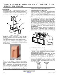
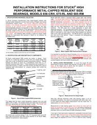
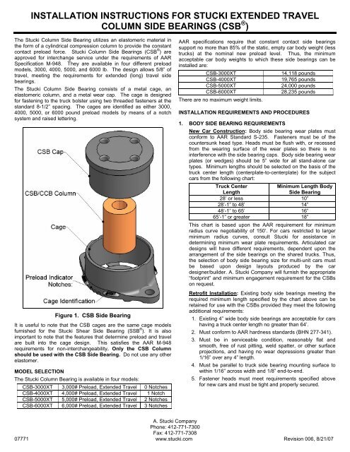
INSTALLATION INSTRUCTIONS FOR STUCKI EXTENDED TRAVELCOLUMN SIDE BEARINGS (CSB ® )The <strong>Stucki</strong> Column Side Bearing utilizes an elastomeric material inthe form of a cylindrical compression column to provide the constantcontact preload force. <strong>Stucki</strong> Column Side Bearings (CSB ® ) areapproved for interchange service under the requirements of AARSpecification M-948. They are available in four different preloadmodels, 3000, 4000, 5000, and 6000 lb. The design allows 5/8” oftravel, meeting the requirements for extended (long) travel sidebearings.The <strong>Stucki</strong> Column Side Bearing consists of a metal cage, anelastomeric column, and a metal wear cap. The cage is designedfor fastening to the truck bolster using two threaded fasteners at thestandard 8-1/2” spacing. The cages are identified as either 3000,4000, 5000, or 6000 pound preload models by means of a notchsystem and raised lettering.Figure 1. CSB Side BearingIt is useful to note that the CSB cages are the same cage modelsfurnished for the <strong>Stucki</strong> Shear Side Bearing (SSB ® ). It is alsoimportant to note that the features that determine preload and travelare built into the cage design. This satisfies the AAR M-948requirements for non-interchangeability. Only the CSB Columnshould be used with the CSB Side Bearing. Do not use any otherelastomer.MODEL SELECTIONThe <strong>Stucki</strong> Column Bearing is available in four models:CSB-3000XT 3,000# Preload, Extended Travel 0 NotchesCSB-4000XT 4,000# Preload, Extended Travel 1 NotchCSB-5000XT 5,000# Preload, Extended Travel 2 NotchesCSB-6000XT 6,000# Preload, Extended Travel 3 NotchesAAR specifications require that constant contact side bearingssupport no more than 85% of the static, empty car body weight (lesstrucks) at the nominal new preload level. Thus, the minimumacceptable car body weights to which these side bearings can beinstalled are:CSB-3000XT14,118 poundsCSB-4000XT19,765 poundsCSB-5000XT24,000 poundsCSB-6000XT28,235 poundsThere are no maximum weight limits.INSTALLATION REQUIREMENTS AND PROCEDURES1. BODY SIDE BEARING REQUIREMENTSNew Car Construction: Body side bearing wear plates mustconform to AAR Standard S-235. Fasteners must be of thecountersunk head type. Heads must be flush with, or recessedfrom the wearing surface of the wear plates so there is nointerference with the side bearing caps. Body side bearing wearplates (or wedges) should be 5” wide for all stand-alone cartypes. Minimum lengths should be selected on the basis of thetruck center length (centerplate-to-centerplate) for the subjectcars from the following chart:Truck CenterMinimum Length BodyLengthSide Bearing28’ or less 10”28’-1” to 48’ 14”48’-1” to 65’ 16”65’-1” or greater 18”This chart is based upon the AAR requirement for minimumradius curve negotiability of 150’. For cars restricted to largerminimum radius curves, consult <strong>Stucki</strong> for assistance indetermining minimum wear plate requirements. Articulated cardesigns will have different requirements, dependent upon thearrangement of the side bearings on the shared trucks. Thus,the selection of body side bearing size for multi-unit cars mustbe based upon design layouts produced by the cardesigner/builder. A. <strong>Stucki</strong> <strong>Company</strong> will furnish the appropriate“footprint” and minimum engagement requirement for the CSBson request.Retrofit Installation: Existing body side bearings meeting therequired minimum length specified by the chart above can beretained for use with the CSBs provided they meet the followingadditional requirements:1. Existing 4” wide body side bearings are acceptable for carshaving a truck center length no greater than 64’.2. Must conform to AAR hardness standards (BHN 277-341).3. Must be in serviceable condition, reasonably flat andsmooth, free of rust pitting, weld spatter, or other surfaceprojections, and having no wear depressions greater than1/16” over any 4” length.4. Must be parallel to truck side bearing mounting surface towithin 1/16” across width and 1/8” end-to-end.5. Fastener heads must meet requirements specified abovefor new cars and must be tight and properly secured.A. <strong>Stucki</strong> <strong>Company</strong>Phone: 412-771-7300Fax: 412-771-7308<strong>07771</strong> www.stucki.com Revision <strong>006</strong>, 8/21/07
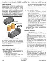
Lubrication: Following installation of side bearing columns andcaps, and prior to lowering the car body onto the trucks, installermust apply lubrication to the side bearing caps. Recommendedlubricant is any lithium-based grease. Do not apply lubricantscontaining graphite or molybdenum disulphide. Lubricantshould be applied as a “dab” approximately 1-1/2” to 2” indiameter to the center area of the wear cap. This is a one-timeonly requirement – no further lubrication of the wear caps orbody side bearings is necessary in service except in repairsituations when both the side bearing wear cap and body sidebearing wear plate are being renewed simultaneously.Level Track Requirements: Installation of side bearingsrequires that the measurements taken to determine side bearingsetup heights be performed with the car setting such that bothtrucks are positioned on reasonably level track. If track is out oflevel across gage by more than 3/16”, proper side bearing setupheights may not be achieved, and performance of the sidebearing as well as operation of the car may be adverselyaffected. Installation, therefore, may require the creation oflevel truck spotting positions by shimming track.Column Preparation for Cold Weather Installation: Toensure mating of car body and truck center plates reasonablysoon following final assembly, it is helpful to store the columnelements in an area where temperature is above 50°F (10°C)for about 24 hours prior to their installation.2. INSTALLATION OF CSB ® CAGESCSB cages may be installed prior to or following themeasurement for setup height procedures (outlined in #3following). This can be done to best suit the installer’sproduction line procedures. If cages are installed prior to gritblast, it is advisable to mask cages to prevent grit from gettinginside.Cages are fastened to the truck bolster (or alternative truck sidebearing mounting surface) using two 7/8-9 AUDITORX ® domehead Camrail ® bolts (7/8-9 TORX ® pan head Camrail ® bolts or7/8-9 socket head cap screws, grade 5 or better, are alsoacceptable). 3-1/4” length is generally suitable for standardtruck bolsters, but installer should choose length to suitapplication. Bolts are applied heads up through cages, nutsinside bolster. If non-breakaway head bolts are used, they mustbe torqued in accordance with the fastener manufacturer’sspecification to yield a clamping force between 20,000 and30,000 pounds (375-400 ft-lbs dry). Nuts should be of the selflockingtype.3. MEASUREMENT TO ACHIEVE PRESCRIBED SETUPHEIGHTObtaining the proper setup height (side bearing height at staticlevel condition) is important to ensure proper performance of theside bearings and safe operation of the car. Car must bepositioned on track meeting the requirements discussed in LevelTrack Requirements above, with both centerplates in contactwith the truck bolster bowls. Solid centerplate lube patties ordiscs must not be in place at this time. Centerplate wear liners(metal or plastic), however, must be installed before measuringfor setup height. Columns must not yet be installed in the sidebearing cages. The vertical space between the truck bolster(mounting surface for the cage) and the underside, or wearingsurface of the body side bearing, must be measured andrecorded at each location (see Figure 2). Measurements shouldbe taken as close to the midpoint of side bearing as possible,and should be taken both sides of center. If the twomeasurements differ by more than 1/16”, the average of bothshould be the recorded height from which shim adjustment willbe calculated. From each measurement, installer mustdetermine what thickness of body side bearing shim must beadded or removed to yield the specified setup height of 5-1/16”,+/- 1/16”. Note that, if nonmetallic centerbowl liners are beingused, these must be in place when the measurements for setupheights are taken, and <strong>Stucki</strong> recommends setting the sidebearings to 1/16” higher height (to 5-1/8”, +/- 1/16”) toaccommodate future compression set of the liners. Note alsothat the standard specified setup height applies to all single unit,or stand-alone cars, all drawbar connected cars, and all endtrucksof articulated multi-unit cars. Setup heights for sidebearings applied to intermediate trucks of articulated cars maybe different based upon customer or car builder requirements.Figure 2. Setup Height Measurement4. INSTALLATION OF COLUMNS AND WEAR CAPS INTOCAGESAfter all body side bearing shim adjustments have beencompleted, the columns and wear caps can be inserted into thecages to complete the installation. If cars have been runthrough grit blast on trucks with CSB cages installed, insides ofcages must be thoroughly cleaned. Columns and caps areinserted into the cages as illustrated in Figure 1. Centerplatesolid lube discs may now be installed. The car body can thenbe lowered onto the trucks. New columns will generally hold thebody from flush centerplate contact for a short period, as willsolid centerplate lube discs. The time required for the elastomerpreload to relax sufficiently to allow the centerplates to contactwill be dependent upon the car body weight and the ambienttemperature, but will normally not exceed 24 hours. The appliedlubrication of the wear caps of the CSB side bearings allows thecars to be moved through curves without problem during thisperiod. It is also important to note that, for the same reason, itis normally not valid to recheck the side bearing setup heightsuntil at least 24 hours after the elements have been installed.A. <strong>Stucki</strong> <strong>Company</strong>Phone: 412-771-7300Fax: 412-771-7308<strong>07771</strong> www.stucki.com Revision <strong>006</strong>, 8/21/07