Mobile Phone Tester Series - Aeroflex
Mobile Phone Tester Series - Aeroflex
Mobile Phone Tester Series - Aeroflex

You also want an ePaper? Increase the reach of your titles
YUMPU automatically turns print PDFs into web optimized ePapers that Google loves.
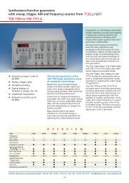
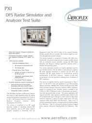
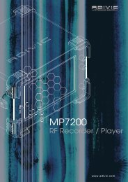
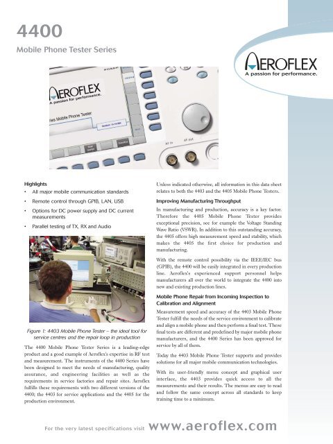
4400<strong>Mobile</strong> <strong>Phone</strong> <strong>Tester</strong> <strong>Series</strong>Highlights• All major mobile communication standards• Remote control through GPIB, LAN, USB• Options for DC power supply and DC currentmeasurements• Parallel testing of TX, RX and AudioUnless indicated otherwise, all information in this data sheetrelates to both the 4403 and the 4405 <strong>Mobile</strong> <strong>Phone</strong> <strong>Tester</strong>s.Improving Manufacturing ThroughputIn manufacturing and production, accuracy is a key factor.Therefore the 4405 <strong>Mobile</strong> <strong>Phone</strong> <strong>Tester</strong> providesexceptional precision, see for example the Voltage StandingWave Ratio (VSWR). In addition to this outstanding accuracy,the 4405 offers high measurement speed and stability, whichmakes the 4405 the first choice for production andmanufacturing.With the remote control possibility via the IEEE/IEC bus(GPIB), the 4400 will be easily integrated in every productionline. <strong>Aeroflex</strong>'s experienced support personnel helpsmanufacturers all over the world to integrate the 4400 intonew and existing production lines.Figure 1: 4403 <strong>Mobile</strong> <strong>Phone</strong> <strong>Tester</strong> – the ideal tool forservice centres and the repair loop in productionThe 4400 <strong>Mobile</strong> <strong>Phone</strong> <strong>Tester</strong> <strong>Series</strong> is a leading-edgeproduct and a good example of <strong>Aeroflex</strong>'s expertise in RF testand measurement. The instruments of the 4400 <strong>Series</strong> havebeen designed to meet the needs of manufacturing, qualityassurance, and engineering facilities as well as therequirements in service factories and repair sites. <strong>Aeroflex</strong>fulfills these requirements with two different versions of the4400; the 4403 for service applications and the 4405 for theproduction environment.<strong>Mobile</strong> <strong>Phone</strong> Repair from Incoming Inspection toCalibration and AlignmentMeasurement speed and accuracy of the 4403 <strong>Mobile</strong> <strong>Phone</strong><strong>Tester</strong> fulfill the needs of the service environment to calibrateand align a mobile phone and then perform a final test. Thesefinal tests are different and predefined by major mobile phonemanufacturers, and the 4400 <strong>Series</strong> has been approved forservice by all of them.Today the 4403 <strong>Mobile</strong> <strong>Phone</strong> <strong>Tester</strong> supports and providessolutions for all major mobile communication technologies.With its user-friendly menu concept and graphical userinterface, the 4403 provides quick access to all themeasurements and their results. The menus are easy to readand follow the same concept across all standards to keeptraining time to a minimum.For the very latest specifications visit www.aeroflex.com
Measurements cannot only be performed in manual mode but alsounder remote control. The 7310 Lector and Scriptor family of testautomation programs facilitates easy-to-use tests; these are startedwith very few mouse clicks and return a simple Pass or Fail verdict alongwith more technical details. See the Lector and Scriptor info sheet formore details.The 4400 <strong>Series</strong> is approved for service by major mobile phonevendors. These provide special software to align and calibrate thephone. In most cases the vendors adapt their control software to the4400, making use of the remote control capabilities of <strong>Aeroflex</strong>'s testers.Research and DevelopmentEngineering and R&D facilities such as design houses requiremeasurement equipment which is easy to use, and which provides highaccuracy. With the 4400 <strong>Mobile</strong> <strong>Phone</strong> <strong>Tester</strong> <strong>Series</strong>, <strong>Aeroflex</strong> offers twoinstruments with the same functionality but different performance,leaving the choice of accuracy to the customer.SPECIFICATIONSpecifications valid after 60 minutes warm-up time at ambienttemperature, specified environmental conditions and typicalmeasurement range, within a period of one year after calibration.The published accuracies are determined in accordance with GUM(Guide to the Expression of Uncertainty in Measurement) and EA(European Co-operation for Accreditation) application documentEA4/02: "Expressions of the Uncertainty of Measurements inCalibration".BASIC RF DATATwo independent synthesizers for RX and TX measurements.Frequency Range430 to 500 MHz (1)800 to 1000 MHz1700 to 2300 MHzAdditional frequency range with the 1209 Downconverter (2)529.6 to 729.6 MHz600.0 to 800.0 MHz1564.8 to 1764.8 MHz2329.6 to 2529.6 MHz2400.0 to 2600.0 MHzFrequency Resolution10 HzFrequency and Level Settling Time350 msRF In/OutN-type female connectorInput/output Impedance50 Ω1)Not available with WCDMA and TD-SCDMA(2) With 1209 Downconverter. Different input and output level ranges apply, seeseparate data sheet for the 1209 Downconverter.(3) If RX signal >–32 dBm and TX signal >10 dBm2VSWR4403 1.24405 1.15 (3) , 1.2Attenuation of Harmonics up to 4 GHz (f0 = 800 to 1000 and 1700 to2000 MHz)>40 dBAttenuation of Non-Harmonics up to 4 GHz at > 5 kHz from Carrier>43 dBTCXO FREQUENCY BASETemperature Characteristic1 x 10 -6 max.Aging Characteristic1 x 10 -6 max./year (at +25°C ±2°C)OCXO FREQUENCY BASE (OPTION)Temperature Characteristic5 x 10 -8 max.Aging Characteristic1 x 10 -7 max./yearEXTERNAL SYNCHRONIZATION INPUTInput level0 to +15 dBmImpedance50 ΩFrequency5, 10, 13 MHz (autodetection)GENERAL DATAControl InterfacesIEEE 488.2 (GPIB)LAN (RJ-45, TCP/IP)USB type A (two on the front, two on the back, for USB flash drive,keyboard and mouse connection)USB type B, for remote controlVGAMains Power Supply94 to 132 V AC187 to 264 V ACPower ConsumptionMax. 140 WOperating Temperature+5°C up to +45°CRelative Humidity
RAPID!Application programming environmentRAPID! = Run Application Programs with Integrated Developmentenvironment.RAPID!Programming language (a modern structured BASIC dialect)Programming environmentInput/Output Control from RAPID! ProgramsGPIBRS-232Parallel port (printer)Floppy and hard disk accessScreen (text-based)Keyboard, incl. bar code reader supportElements for Structured ProgrammingGlobal and local variablesFunctions, subroutinesLibrariesElements for Event-Driven ProgrammingKeyboard eventsSCPI eventsExternal interface eventsOther Programming FeaturesDirect access to SCPI command set,to control the 4400 and collectmeasurement results for postprocessingInformation hiding (program files can be protected against reading by theuser)Scripting (to create or change mobile tests easily and efficiently)Functions of Built-In Programming EnvironmentFile managerEditor (multiple files)Runtime I/O screenDebug screen, display of variables contentsGENERAL OPTIONS<strong>Aeroflex</strong> provides additional options for the 4400 <strong>Mobile</strong> <strong>Phone</strong> <strong>Tester</strong><strong>Series</strong>, facilitating tests of a mobile phone under variousconditions or against special requirements.Figure 3. Start menu for evaluation tests provided in RAPID!4470 Audio Option, 4471 Basic Codec Option and 4472 CodecExtension OptionWith <strong>Aeroflex</strong>'s 4400 <strong>Series</strong> and the Audio and Codec options, <strong>Aeroflex</strong>provides complete testing solutions for mobile phones.The Audio and Codec Options for the <strong>Aeroflex</strong> 4400 <strong>Series</strong> help tomeasure and test the audio capabilities of the mobile phone,ensuring its high quality. These options have been designed for theparticular needs of R&D, production, repair/service and qualityassurance.The options can be easily integrated in the <strong>Aeroflex</strong> 4400 <strong>Mobile</strong> <strong>Phone</strong><strong>Tester</strong>, resulting in a compact RF and AF test system.AudioThe Audio Option can test and evaluate the individual audiocomponents or the complete audio path of the mobile. There aredifferent ways to stimulate the mobile phone and to verify the audioquality.The generated signal can be fed into a loudspeaker to stimulate themicrophone; it can also stimulate the mobile at the headset input.Using the codec options, you can transmit voice signals even over theGSM traffic channel.The audio signal from the mobile can be evaluated using either thebasic audio analyzer or the unique audio spectrum analyzer. A highimpedance AF input, an auxiliary input for the microphone and thetraffic channel (using the additional codec options) can be used assources for the analysis.Figure 2: The 1209 Downconverter is an optional frequencyextension for Bluetooth, WLAN, GPS tests and <strong>Mobile</strong> TVstandards.GSM CodecsThere are two different codec options for GSM available: the 4471 BasicCodec Option for Full Rate (FR) speech and the 4472 Codec ExtensionOption for Enhanced Full Rate (EFR). These codecssupplement the audio measurements, allowing audio signals to begenerated and tested via the air interface.3
4481 AM Signal Generator OptionThe AM Signal Generator allows the tuning of certain phones inasynchronous (or non-call) mode. The modulation index and themodulation signal can be varied to support some vendor-specific AMsuppression measurements.4473 MS Power Supply OptionIn production lines and service centres, mobile phone testing isusually conducted using an external power supply. Now, <strong>Aeroflex</strong> helpsmobile manufacturers and service factories optimise their workspace,instrument control and budget by integrating the power supply into the<strong>Aeroflex</strong> 4400 <strong>Series</strong>.<strong>Aeroflex</strong>’s MS Power Supply Option enhances the functionality of the4400 <strong>Mobile</strong> <strong>Phone</strong> <strong>Tester</strong> <strong>Series</strong> by enabling engineers to eliminate theexternal power supply. With this easy-to-use add-on, therevolutionary 4400 supplies the mobile with DC power and tests RF andaudio, all from one instrument.The option was developed in consultation with mobile phonemanufacturers and service centres with the aim of improving mobilephone testing processes and environments.This innovative testing option provides a number of benefits:• Easier programming - The option employs remote control andRAPID! integration based on SCPI and 4400 standards.• Streamlined troubleshooting - Quick separation of handset andpower supply problems ensures faster problem resolution.• Minimize space and costThe MS Power Supply Option not only reduces installation andmaintenance costs but also saves money over time by reducing thenumber of devices manufacturers and service centers need to hold.The option’s simple-to-interpret graphical user interface, whichreduces both the need for training and the time taken on each test,further enhances the cost savings.• Multiple, simultaneous testing capabilitiesThe MS Power Supply Option can support GPRS applicationsbecause it is able to feed currents for the transmission of at leasttwo time slots per frame. The number of time slots is limited onlyby the current level in transmit mode.• One-box solutionThe MS Power Supply Option is shipped with a one-meter cable,designed to plug simply and easily into the power supply socket onthe front panel of your 4400. The open-ended termination on thiscable provides free adaptation into an existing test system.SPECIFICATIONSOUTPUT VOLTAGERange0 to 10 VResolution50 mVAccuracy (with constant current)±20 mVMaximum Output CurrentContinuous (
4474 MS CURRENT MEASUREMENTOPTIONIn specific test stations at manufacturing lines and repair stations,measurement of the current from the battery is a "must" in order toidentify any failure on the PCB (Printed Circuit Board). Qualityassurance measures the current in order to characterize standby andtalk times.For this range of applications the 4400 plug-in option "MS CurrentMeasurement" substitutes an external current meter and measurespower and current, which the mobile drains from the battery. The usercan choose between a numerical measurement and a unique graphicalrepresentation of the current versus time measurements. The currentchanges dynamically as the mobile’s power amplifier generates the RFbursts.In addition the option provides a statistical evaluation for minimum,maximum, average and peak value regarding the selected duration time.The duration of the graphical representation is 4.615 ms which enablesthe user to analyze a complete GSM TDMA frame.The 4474 MS Current Measurement Option is an extension of the 4473MS Power Supply Option. To connect the 4400 with the mobile, a powersupply cable is delivered with the option. An open-endedtermination on this cable provides free adaptation into an existing testsystem.Both options extend the test application area of the 4400. The 4400 isnow able to supply the mobile under test, measures RF and audioquality and the power consumption with one test instrument.SPECIFICATIONSMEASUREMENTRange0 to 400 mA or 0 to 4 AResolution (at 400 mA)0.1 mAResolution (at 4 A)1 mAAccuracy2%Offset±5 mAOutput Voltage Range0 to 10 VRecording Duration4.615 ms (1 TDMA frame)Resolution960 pointsSample Rate192 000 samples/secConnection CableA 0.5 meter long power supply connection cable with open ends for freeadaptation of user needs is delivered with the option.The benefits in brief:• Integrated current meter, e.g. to identify short-circuitsituations, eases handling for the user• The 4400 user can test RF, audio and power consumption withone test instrument• No additional external current meter necessary, this saves space intest systems• Power, peak current and average current measurementspossible• Easy-to-read numerical measurement display• Current vs. time measurements for the analysis of burst currentcharacteristics with selectable resolutions• Statistical evaluation and overload detection• Battery replacementFor the very latest specifications visit www.aeroflex.com5
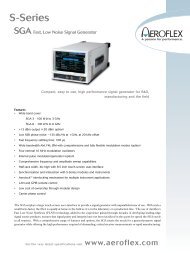
OPTIONS FOR WCDMA (UMTS) ANDHSDPAThe WCDMA offering on the 4400 consist of two main options, the4466 WCDMA/UMTS Non-Call Mode Option and the 4467WCDMA/UMTS Call Mode Option. These software options are basedupon the 4479 Baseband Processing Hardware.4466 WCDMA Non-Call Mode OptionThe Non-Call Mode Option, sometimes also known as asynchronousmode or non-signaling mode, offers all the functionality required totune a WCDMA mobile phone in a production or high level serviceenvironment. It offers all the functions necessary to generate andanalyze a WCDMA signal. This functionality is dedicated to thealignment and calibration of the Printed Circuit Board (PCB) of a 3Gmobile phone; these two steps are necessary to guarantee that themobile phone's radio frequency parameters are within the limitsspecified.Typical tests include:• Power measurements• Modulation quality measurements• Constellation display• Code domain power measurements• Spectrum measurements• TX-RX sweep calibrationTo tune the receiver of a 3G mobile phone the 4400 offers varioussignals - a Continuous Wave (CW) signal, a Frequency Modulated (FM)signal and the WCDMA-modulated signal.There are more features available, like the power staircasemeasurement or the zero-span-analyzer. The power staircase test hasbeen designed for specific measurements of the power changes; thezero-span-analyzer can perform the same in a more flexible way anddisplays power versus time, just as a spectrum analyzer does in zerospanmode. These features can be used to display nearly allsignals which are generated within the frequency range of the 4400.Overall the non-call mode functionality is mostly used through remotecontrol and in cooperation with service software controlling both thetester and the device under test.4467 WCDMA Call Mode OptionThe call mode option of the 4400 is prepared for the requirements of afinal test. These tests are based on 3GPP/FDD Release '99 and ETSIspecification TS 134.121.Call mode or signalling tests are necessary to test the behaviour of theWCDMA (UMTS) mobile phone in a network, closer to the reality.Therefore the 4400 acts as a Node B (WCDMA base station),supporting the necessary signalling exchange.All the relevant parameters, such as the configured downlinkchannels, can be configured. The 4400 supports the required callprocessing algorithm for call set up (mobile-terminated call,mobile-originated call) and also for loopback mode on one of theReference Measurement Channels (RMC); these channels arespecified for transmitter and receiver testing.The 4400 <strong>Mobile</strong> <strong>Phone</strong> <strong>Tester</strong> <strong>Series</strong> provides a long list oftransmitter measurements, which can be divided into modulationquality, power, code domain and spectrum measurements withadditional reports from the phone. Receiver measurements are alsoincluded. Fast testing on different frequency channels is supported withthe handover procedure to keep test time to a minimum.Figure 3: Receiver Sensivity Level Estimation with BER/BLERMeasurementHSDPAHigh Speed Downlink Packet Access is an optimization forUMTS/WCDMA in the Downlink.The HSDPA testing solution for the 4400 <strong>Mobile</strong> <strong>Phone</strong> <strong>Tester</strong> <strong>Series</strong>consists of two options: the 4456 HSDPA Non-Call Mode Option andthe 4455 HSDPA Call Mode Option. Each of these options requires therelated WCDMA option– and the 4479 Baseband Processing Hardwareto be installed.4456 HSDPA Non-Call Mode OptionThe HSDPA Non-Call Mode Option provides all the necessaryfunctionality to calibrate and align an HSDPA-capable device inproduction or high level service environment. For this purpose, it offersgenerator and analyzer functions with measurements asfollows:Power measurements, modulation quality, code domain power andspectrum measurements4455 HSDPA Call Mode Option4455 HSDPA Call Mode Option offers the functionality to fully test anHSDPA-capable device according to 3GPP Release 5 specification TS134 121. The 4400 simulates a radio cell with HSDPA capabilities,where the device can log onto (PS attach). Once successfullyregistered, an RMC-based connection can be established and HSDPAdata is transmitted. Based on the connection settings,different tests can be performed such as:• Power measurements (e.g. maximum power)• Modulation quality (e.g. peak and RMS error vector magnitude(EVM))• Code domain power measurements (e.g. peak code domain error(PCDE))• Receiver characteristics (e.g. maximum input level)• Receiver performance (e.g. CQI reporting, data rate throughput/BLER)6
Distortion Tolerance
Display Range80 dBResolution0.1 dBOccupied BandwidthRange1 to 6 MHzAccuracy±100 HzResolution15 kHzSPECTRUM EMISSION MASKMeasurement Filter±2.515 to ±3.485 MHz 30 kHz Gaussian±4 to ±12 MHz 1 MHz GaussianDynamic range±2.515 to ±3.485 MHz: >70 dB±4 to ±12 MHz: >65 dBResolution0.1 dBNON-CALL MODE FUNCTIONSWCDMA/HSDPA ANALYZERPower MeasurementsPeak power, mean powerSpectrum MeasurementsOccupied bandwidth (OBW), adjacent channel power leakage ratio(ACLR), spectrum emission mask (SEM)Modulation QualityError vector magnitude (EVM), magnitude error, frequency error, phaseerror, rho, I/Q offset, I/Q imbalance, constellation displayCODE DOMAIN MEASUREMENTSPeak code domain error (PCDE), code domain powerPOWER VS. TIMEZero-span analyzer (flexible power vs. time measurements)Sweep Time1 to 85 ms 1Reference Level–23 to 36 dBmFilter30 kHz, 100 kHz, 4.6848 MHzGENERATORCW, FM and WCDMA signal151 ms for 4.6848 MHz filterCALL MODE FUNCTIONSWCDMA CALL PROCESSINGSupported BandsBand I- 1920 to 1980 MHz (UL)2110 to 2170 MHz (DL)Band II- 1850 to 1910 MHz (UL)1930 to 1990 MHz (DL)Band III- 1710 to 1785 MHz (UL)1805 to 1880 MHz (DL)Band IV- 1710 to 1755 MHz (UL)82110 to 2155 MHz (DL)Band V- 824 to 849 MHz (UL)869 to 894 MHz (DL)Band VI-830 to 840 MHz (UL)875 to 885 MHz (DL)Band VIII-880 to 915 MHz (UL)925 to 960 MHz (DL)Band IX- 1749.9 to 1784.9 MHz (UL)1844.9 to 1879.9 MHz (DL)Band X- 1710 to 1770 MHz (UL)2110 to 2170 MHz (DL)Supported ProceduresUniversal Routing Update (URA), mobile originated call, mobileterminated call, call clearing by mobile and tester, inter-frequencyhandover (channel change), inter-RAT handover (to GSM/GPRS/EDGE)Reference Measurement Channels According to 3GPP TS 134121RMC 12.2, 64, 144, 384 kbpsHSDPA Specific Reference ChannelsH-Set 1 – 6 QPSK, 16QAM with AWGN and fading (PA3)Transmitter MeasurementsPeak and mean powerMin and max output powerInner loop power controlOpen loop power controlHS-DPCCH powerSpectrum MeasurementsOccupied bandwidth (OBW)Adjacent channel power leakage ratio (ACLR)Spectrum emission mask (SEM)Modulation Quality MeasurementsError vector magnitude (EVM)Magnitude errorFrequency errorPhase errorRhoI/Q offsetI/Q imbalanceConstellation displayPhase discontinuityHSDPA: Error vector magnitudePhase discontinuityRelative code domain powerRelative code domain errorCode Domain MeasurementsPeak code domain error (PCDE), code domain powerReceiver MeasurementsBER/BLER measurementsUE Info with UE Measurement ReportHSDPA: Maximum throughput testBLERDemodulation of HS-DSCHReporting of channel quality indicator (CQI)
OPTIONS FOR TD-SCDMATD-SCDMA (Time Division Synchronous CDMA) is athird-generation wireless communications standard for China,combining Time Division Multiplex Access (TDMA) technologywith a synchronous CDMA component.<strong>Aeroflex</strong>'s TD-SCDMA testing solution is based on the 4400 <strong>Series</strong><strong>Mobile</strong> <strong>Phone</strong> <strong>Tester</strong>, the 4450 TD-SCDMA Non-Call Mode Option,the 4451 TD-SCDMA Call Mode Option and the 4479 BasebandProcessing Hardware.4450 TD-SCDMA Non-Call Mode OptionThe 4450 TD-SCDMA Non-Call Mode Option can be seen as acombined signal analyzer and generator in one instrument used inR&D, production and high level service environments.The analyzer functionality provides the following features:• Power measurements, such as channel, mean, peak, off-powermeasurementsFigure 5: TD-SCDMA power measurements• Modulation quality measurements with measurements like ErrorVectorMagnitude (EVM RMS), frequency, magnitude and phase error• Constellation display• Code domain power measurements• Spectrum measurementsSignals such as Continuous Wave (CW), burst and TD-SCDMAtogether with QPSK modulation and various types of payload dataallow a flexible tuning of TD-SCDMA handset receivers.4451 TD-SCDMA Call Mode OptionThe Call Mode Option supports the functionality required for typicaltests on a TD-SCDMA mobile phone. These tests are based on the3GPP/TDD Release ’99 and ETSI specification TS 134.122 (LowChip Rate – LCR).The call processing is required to simulate a TD-SCDMA basestation and test the proper behaviour of the TD-SCDMA mobilephone in a network. The 4400 in this way acts as a Node B(TD-SCDMA base station), supporting the necessary signalling. Allthe relevant parameters, such as the configured downlink channels,can be configured. The 4400 supports the basic registrationprocedure, as well as the required call processing for the call setup(mobile-terminated and mobile-originated) and for the test loopbackmode on one of the Reference Measurement Channels (RMC); thesechannels are specified for transmitter and receiver testing.The 4400 <strong>Mobile</strong> <strong>Phone</strong> <strong>Tester</strong> <strong>Series</strong> provides a long list oftransmitter measurements, which can be divided into modulationquality, power, code domain and spectrum measurements withadditional measurement reports from the mobile phone. Receivermeasurements are also included and supported. In order to supportfast testing on various frequency channels, handover procedures arealso included – this will keep measurement time to a minimum.Figure 6: Constellation DisplayGENERAL DATAStandard3GPP-TDDSymbol Rate1.28 McpBandwidth1.6 MHzRF GENERATORModulation typeCW, burst, TD-SCDMA downlinkTD-SCDMA SIGNAL GENERATORFrequency Range800 to 1000 MHz1700 to 2300 MHzFrequency Resolution1 HzFor the very latest specifications visit www.aeroflex.com9
Output Level Range–120 to –13 dBmOutput Level Accuracy0.7 dB, typ. ±0.4 dBOutput Level Resolution0.1 dBError Vector Magnitude (EVM)58 dB, second adjacent channelDisplay Range80 dBResolution0.1 dBOCCUPIED BANDWIDTHRange1 MHz to 4 MHzAccuracy±100 kHzResolution15 kHzSPECTRUM EMISSION MASKMeasurement Filter±0.8 MHz to ±2.4 MHz 30 kHz Gaussian±2.4 MHz to ±4 MHz 1 MHz GaussianDynamic Range±0.8 MHz to ±2.4 MHz >70 dB±2.4 MHz to ±4 MHz >65 dBResolution0.1 dB10
NON-CALL MODE FUNCTIONSTD-SCDMA ANALYZERPower MeasurementsChannel power, peak/mean/off power, power on/off maskSpectrum MeasurementsModulation spectrumOccupied bandwidth (OBW)Adjacent Channel leakage power ratio (ACLR)Spectrum emission mask (SEM)Modulation QualityEVM, frequency error, magnitude error, phase error, I/Q offset, I/Qimbalance, RhoCode Domain MeasurementsPeak code domain error (PCDE), code domain spectrumGENERATORSignal TypeCW, burst, TD-SCDMAModulationNone, QPSKDownlink Timeslots1 to 6Payload DataPN9, PN15, PN23, all 0s, all 1s, 1010..., 1100..., 11110000,1...10...0Data Rate (Reference Measurement Channel – RMC)12.2 kbpsCALL MODE FUNCTIONSTD-SCDMA CALL PROCESSINGSupported Bands1900 to 1920 MHz (UL & DL)2010 to 2025 MHz (UL & DL)1850 to 1910 MHz: (UL & DL)1930 to 1990 MHz: (UL & DL)1910 to 1930 MHz: (UL & DL)Supported ProceduresRegistration, mobile originated call, mobile terminated call, callclearing by mobile and tester, inter-frequency handover (channel change)Reference Measurement Channels according to 3GPP TS 34.122RMC 12.2 kbps (single code and multicode)RMC 64 kbpsTransmitter MeasurementsPeak and mean power, min and max power, inner loop power control,open loop power control, Transmit ON/OFF Time maskSpectrum MeasurementsOccupied bandwidth (OBW), adjacent channel power leakage ratio(ACLR), spectrum emission mask (SEM)Modulation Quality MeasurementsError vector magnitude (EVM), magnitude error, frequency error, phaseerror, rho, I/Q offset, I/Q imbalance, constellation displayCode Domain MeasurementsPeak code domain error (PCDE), code spectrumReceiver MeasurementsBER/BLER measurementsUE Info with UE Measurement Report(e.g. UE power, P-CCPCH RSCP, path loss)OPTIONS FOR CDMA2000The CDMA2000 system options for the 4400 <strong>Series</strong> enable users inR&D, manufacturing and service to test subscriber terminals which arebased on the cdmaOne and CDMA2000 technologies. The 4447CDMA2000 1xRTT Non-Call Mode Option supports asynchronousmeasurements and the 4448 CDMA2000 1xRTT Call Mode Optionsupports synchronous measurements, so the combination of the bothallow the user to perform alignment as well as functional testing ofterminals.Supported features are:• cdmaOne and CDMA2000 call processing including registration,MS/BS originated call, MS/BS termination, handovers• Fast power measurements including Min/Max power, open looppower, gated power, closed loop power and access probe power• Modulation quality measurements including waveform quality andcode domain measurements• Receiver performance testing including receiver sensitivity anddynamic range using the FER feature• AM generation for calibration of terminals supporting ZIF (zerointermediate frequency) based chipsetsThe CDMA2000 System Option supports the following bands: 0-USCellular, 1-US PCS, 2-TACS, 3 JTACS, 4-Korean PCS, 5-NMT-450, 6IMT 2000, 8-1800 MHz, and 9-900 MHz.Figure 7: Basic Screen CDMA2000For the very latest specifications visit www.aeroflex.com11
Figure 8: Modulation Quality MeasurementRF GENERATORCDMA GENERATORLevel Range (AWGN Off)–120 dBm to –15 dBmLevel Range (AWGN On)–120 dBm to –27 dBmLevel Accuracy (AWGN Off), (–110 dBm to –15 Bm)4403 ±1.4 dB4405 ±0.9 dB, typ. ±0.6 dBLevel Resolution0.1 dBWaveform Quality (rho)>0.97Typ. >0.99Carrier Feedthrough1.8 MHzAWGN, Level Range Relative to CDMA Signal+5 to –10 dBAWGN Level Accuracy (relative to signal)±0.5 dBCODE CHANNELSSector AF-PICH, F-SYNC, F-FCH–5 dB to –32 dBF-QPCH+2 to –5 dB relative to PilotF-OCNSLevel calculated by 4400Sector BF-PICH, F-FCH–5 dB to –32 dBF-OCNSLevel calculated by 4400AMPS GENERATORLevel Range–120 dBm to –15 dBmLevel Accuracy4403 ±1.4 dB4405 ±0.9 dB, typ. ±0.6 dBLevel Resolution0.1 dBModulationFM or noneFM Modulation TypesMod A 5970 Hz, 6000 Hz, 6030 HzMod B 1 kHz or offRF ANALYZERCDMA/AMPS POWER METERCDMA Level Range–70 dBm to +36 dBmAMPS Level Range–40 dBm to +36 dBmLevel Resolution0.1 dBLevel Accuracy4403 ±1.2 dB4405 (–10 dBm to +36 dBm) ±0.5 dB(–60 dBm to –10 dBm) ±0.6 dB(–70 dBm to –60 dBm) ±0.7 dBMODULATION QUALITY FOR CDMA2000Level Range–30 dBm to +36 dBmFrequency Error Range±1 kHzResolution1 HzAccuracy (relative to freq. base)±10 HzWAVEFORM QUALITYRange0.9 to 1.0Accuracy±0.003TIME OFFSETRange±5 µsAccuracy±100 nsCODE DOMAIN MEASUREMENTS (1XRTT channels)Code Channels16 16W 0 to W 15Code Power Range0 to 40 dBc (relative to total power)12
Code Power Resolution0.1 dBCode Power Accuracy±0.1 dBNumber of Code Channels1 to 6Timing Range0 to 200 nsTiming Resolution1 nsTiming Accuracy±2 nsCode Domain Power Range±3.75 dB (relative to reverse pilot)Code Domain Power Resolution0.1 dBCode Domain Power Accuracy±0.1 dBMODULATION SPECTRUMDisplay Range80 dBResolution Bandwidth5 kHz, 10 kHz, 30 kHzSpan (selectable)±2.5 MHz, ±1.25 MHz, ±500 kHzACPMDisplay Range80 dBFrequencies According to IS-98D up to 2.5 MHz from Centre FrequencyMeasurementsSpectrum due to modulationMODULATION ANALYZER FOR AMPSLevel Range–15 dBm to +36 dBmFrequency Error Range±5 kHzResolution1 HzAccuracy (relative to freq. base)±20 HzDeviation Range0 to 30 kHzDeviation Resolution1 HzDeviation Accuracy±5%Audio Deviation Filter300 kHzSAT Frequency Range±5 HzST Frequency Range±5 HzSAT & ST Frequency Resolution1 HzSAT & ST Frequency Accuracy±0.1 HzNON-CALL MODE FUNCTIONSCDMA GENERATORSignal typeContinuousModulationNone, BPSK/QPSKUser-definable parameters for CDMA cell simulationSID, NID, MCC, MNC, PN offsetCDMA ANALYZERSupported Signal TypesOQPSK, HPSKSupported transmitter measurements power gated power, waveformquality, code domainAMPS GENERATORSignal TypesContinuousModulationNone, FMAMPS ANALYZERSupport Signal TypesFMSupported Transmitter MeasurementsPower, frequency error, SAT & ST frequency and deviation, audio deviation,SINAD – requires Audio OptionCALL MODE FUNCTIONSCDMA2000 CALL PROCESSINGSupported CDMA2000 bandsband 0 – US cellular (ch 1 to 1023)band 1 – PCS band (ch 1 to 1199)band 2 – TACS band (ch 1-1000, 1329-2047)band 3 – JTACS bandband 4 - Korean PCS (ch 1 to 599)band 5 – NMT-450band 6 – IMT-2000 (ch 1 to 1199)band 8 – 1800 MHz (ch 1 to 1499)band 9 – 900 MHz (ch 1 to 699)Supported ProceduresRegistrations, mobile-originated call, mobile-terminated call, intracellhandover, cross-band handover, call clearing by MS, call clearing by4400SPECIAL FUNCTIONSCall State DiagramMS Information Display<strong>Mobile</strong> ID Number (MIN), Equipment Serial Number (ESN), IMSI (class 0and 1), type, slot class, slot index, power class, transmit mode, digitsdialedCommon Control Channel ParametersSID, NID, MCC, MNC, PN OffsetAccess Channel ParametersNominal power, initial power, power step, number steps, requestFor the very latest specifications visit www.aeroflex.com13
sequences, response sequences, timeout, preamble lengthPaging RateFullRadio Configuration CombinationsF-RC1/R-RC1, F-RC2/R-RC2, F-RC3/R-RC3, F-RC4/R-RC3,F-RC5/R-RC4Service Options1 – 9.6 kbps voice, 2 – 9.6 kbps loopback, 3 – EVRC voice, 9 – 14.4kbps loopback, 17 – 14.4 kbps voice, 55 – RC1, RC2, RC3, RC4,RC5 loopback, 32768 – 14.4 kbps voiceReverse Link Power Control ModesAlternating, all up, all down, activeFundamental Channel ParametersWalsh code, data rate, pattern (PN15, voice loop back or canned),voice loopback delayFundamental channel data rates – forwardRC1 - 1.2, 2.4, 4.8, 9.6 kbpsRC2, RC5 - 1.8, 3.6, 7.2, 14.4 kbpsRC3, RC4 - 1.5, 2.7, 4.8, 9.6 kbpsFundamental channel data rates - reverseRC1 - 1.2, 2.4, 4.8, 9.6 kbpsRC2,RC4 - 1.8, 3.6, 7.2, 14.4 kbpsRC3 - 1.5, 2.7, 4.8, 9.6 kbpsCDMA2000 TRANSMITTER MEASUREMENTSPower MeasurementsMinimum/maximum RF power, open loop power (level and timing), gatedoutput power, access probe power, closed loop power (min./max./rangeonly), stand-by powerModulation Quality Measurementsrho, frequency error, rms vector error, time offset, amplitude imbalance,code domain power (graphical and data), code channel timeoffset, codechannel phaseCDMA2000 RECEIVER MEASUREMENTSReceiver PerformanceSensitivity, dynamic range (frame error rate)Demodulator PerformanceDemodulation of forward traffic with AWGN<strong>Mobile</strong> ReportedFER, pilot strengthAMPS CALL MODE FUNCTIONSAMPS CALL PROCESSINGSupported ProceduresHandoff CDMA to analog, handoff analog to analog, power level change,call clearing by MS or 4400AMPS Transmitter MeasurementsPower, frequency error, SAT & ST frequency and deviation, Audiodeviation, SINAD – requires Audio OptionAMPS Receiver MeasurementsReceiver sensitivity with SINAD (requires Audio Option)OPTIONS FOR 1XEV-DOThe 1xEV-DO offering on the 4400 <strong>Mobile</strong> <strong>Phone</strong> <strong>Tester</strong> <strong>Series</strong>consist of two main options, the 4452 1xEV-DO Non-Call Mode Optionand the 4453 1xEV-DO Call Mode Option.These software options are based upon the 4479 Baseband ProcessingHardware.4452 1xEV-DO Non-Call Mode OptionThe Non-Call Mode Option, sometimes also known as asynchronousmode or non-signaling mode, offers all the functionality required totune a 1xEV-DO Rev.0 or Rev. A mobile phone in a production or highlevel service environment. It provides all the functions required to analyzea 1xEV-DO signal. This functionality is dedicated to thealignment and calibration of the Printed Circuit Board (PCB) of a1xEV-DO mobile terminal; these two steps are necessary toguarantee that the mobile terminal's radio frequency parameters arewithin the limits specified.Typical tests include:• Power measurements• Modulation quality measurements• Code domain power measurements• Spectrum measurementsOverall the non-call mode functionality is typically used through remotecontrol and in cooperation with service software controlling both thetester and the device under test.4453 1xEV-DO Call Mode OptionThe 4453 1xEV-DO Call Mode Option enables users to perform a functionaltest on a 1xEV-DO Revision 0 or Revision A mobileterminal. The functional test consists of establishing a connection tothe terminal in a similar manner as a connection with a live network.Once a connection is establish, the appropriate RF transmitter andreceiver measurements may be performed.The Call Mode Option allows the user to setup the forward linksignaling parameters and traffic channel parameters, thus allowing theuser to simulate their specific network. Once the signaling parametersare setup the user may perform one of the followingsignaling procedures:• AT Session Open• AT & AN Connection• AT & AN Release• AT & AN Session Close• HandoverOnce the terminal is in a connection state, an array of transmitter andreceiver test may be performed. The transmitter test consist of:minimum/maximum RF power, access probe power, closed loop power(min./max./range only), stand-by power, modulation quality measurementsincluding rho, frequency error, rms vector error, time offset,amplitude imbalance and code domain error. The receiverperformance may be verified by utilizing the FTAP/RTAPapplications to test sensitivity and dynamic range via a packet error ratemeasurement.14
RF ANALYZERFigure 9: EVDO Basic Menu with Call State DiagramFigure 10: Overview of the transmitter quality parametersSPECIFICATIONSRF GENERATORLevel Range–120 dBm to –15 dBmLevel Resolution0.1 dBLevel Accuracy(–110 dBm to –15 dBm) ±0.7 dBTyp. ±0.4 dBWaveform Quality (rho)>0.97Typ. >0.99Carrier Feedthrough
Resolution Bandwidth15 kHz, 30 kHzSpan (selectable)±2.5 MHz±500 kHzACPMDisplay Range80 dBFrequencies according to IS-98DUp to 2.5 MHz from centre frequencyMeasurementsSpectrum due to modulationNON-CALL MODE FUNCTIONSMeasurementsPower measurementsModulation quality measurementsRhoFrequency errorRms vector errorAmplitude imbalanceCode domain powerModulation spectrumCALL MODE FUNCTIONSSupported RevisionsRev. 0, Rev. ASupported Bandsband 0 - US cellular (ch 1 to 1023)band 1 - PCS band (ch 1 to 1199)band 2 - TACS band (ch 1-1000, 1329-2047)band 3 - JTACS band (ch 1-799, 801-1039, 1041-1199, 1201-1600)band 4 - Korean PCS (ch 1 to 599)band 5 - NMT-450 (ch 1-300, 1039-1473, 1792-2016)band 6 - IMT-2000 (ch 1 to 1199)band 8 - 1800 MHz (ch 1 to 1499)band 9 - 900 MHz (ch 1 to 699)Supported ProceduresAT Session OpenAT & AN ConnectionAT & AN ReleaseAT & AN Session CloseHandoverTerminal informationHardware IDHardware ID typeSession seedUATI 024UATI color codeAccess ParametersOpen loop adjust (0 to 255 dB)16Preamble length (0 to 7 frames)Probe initial adjust (-15 to +16 dB)Probe num step (1 to 15)Probe power step (0 to 7.5 dB)Probe sequence max (1 to 15)Reverse Channel Gain ParametersAck channel (-3 to +6 dB)DRC channel (-9 to +6 dB)Data offset nominal (-3.5 to 4.0 dB)Data offset rate (for various rates)General ParametersControl channel numberTotal RF powerPN offset (0 to 511)Call ParametersPhysical Layer SubtypeApplicationFTAP/FETAP rateRTAP/RETAP rateACK channel bit fixed mode attribAT directed packetsReverse closed loop power controlAT max powerMAC indexTransmitter MeasurementsPower measurementsMinimum/maximum RF powerModulation quality measurementsRhoFrequency errorRms vector errorTime offsetAmplitude imbalanceCode domain powerReceiver MeasurementsReceiver performance sensitivityDynamic range (packet error rate)
OPTIONS FOR GSM, GPRS AND EDGEThe 4400 <strong>Mobile</strong> <strong>Phone</strong> <strong>Tester</strong> <strong>Series</strong> supports GSM and itsenhancements GPRS and EDGE with different basic options:the GSMnon-call mode and call mode options, the GPRS non-call mode and callmode options, and the EDGE non-call mode option and call modeoptions.GSM System OptionsWorldwide the GSM standard is being applied in four differentfrequency bands, all of which are supported by the GSM systemoptions.The 4457 GSM Call Mode Option offers a signaling mode in which the4400 is able to emit a signal similar to that of a GSM base station.Various signaling parameters can be adjusted to test a GSM mobilephone under different conditions.The parameter menu allows signaling parameters to be easily changed.From the GSM cell parameters, across the definition of SMS messageclass, to the call set up procedure details, a lot of parameters areaccessible in the 4400. A range of measurements are supported to testfrequency and phase error, power, spectrum, and various receiverquality parameters.Figure 11: GSM Basic ScreenThe call mode option includes a generic test script to run testsautomatically, without user intervention. This test script consists of afinal test of a GSM mobile phone operating in one or several of theGSM frequency bands, which are GSM 850 (U.S. cellular band), GSM900, GSM 1800 and GSM 1900 (U.S. PCS band).The generator/analyzer mode of the 4458 GSM Non-Call Mode Optionprovides basic signal generation capabilities as well asfrequency and phase, burst (power) and spectrum measurements. Thisfunctionality is not limited to GSM channels but available for the wholefrequency range supported by the 4400.GPRS System OptionsGPRS (General Packet Radio Service) adds higher data ratecapabilities to GSM by combining a packet data protocol with bundlingof multiple time slots. The 4462 GPRS Call Mode Option allowstesting of the packet data protocol capability as well as themultislot transmit and receive quality during a connection. Testswithout the connection setup can be done with the 4454 GPRSNon-Call Mode Option.Users who need to test both GSM and GPRS in call mode andnon-call mode, can also use the 4463 GSM/GPRS System Optioncombining the capabilities of all the four system options.EDGE System OptionsA further increase in data throughput is achieved with EDGE(Enhanced Data rates for the Global Evolution), also called EnhancedGPRS. EGPRS introduces a higher modulation format (8-PSK) whichrequires new tests and measurements.The modulation quality for EDGE-enabled mobile phones is expressedin Error Vector Magnitude (EVM), origin offset and I/Q imbalance.RF GENERATORFigure 12: RF Generator/Analyzer ModeLevel Range–120 dBm to –10 dBmLevel Accuracy (–110 dBm to –10 dBm)4405 0.7 dB, typ. 0.3 dB4403 0.9 dB, typ. 0.4 dBLevel Resolution0.1 dBPhase Error Rms2.3°, typ. 1.1°RF ANALYZERPeak Power Level Range–10 dBm to +36 dBmDynamic Range72 dBUsable Down To–30 dBmPhase and Frequency MeasurementsFor the very latest specifications visit www.aeroflex.com17
Graphical DisplayPhase Error vs. TimeMarker Functions2 markers, difference indicationVertical Display Range±2°, ±5°, ±10°, ±20°, ±50°Horizontal Display Range150 bit periodsFREQUENCY ERRORDisplayCurrent/average/min./max.Range±100 kHzResolution1 HzAccuracy at 800 MHz to 1000 MHzRMS EVMDisplayCurrent/average/min./max.Range0 to 50%Resolution0.1%Accuracy
Level RepetitionDisplay Range4405 0.01 dB80 dB4403 0.03 dBFrequenciesLevel ResolutionAccording to ETSI GSM 11.10 up to 1.8 MHz from centre frequency0.01 dBMeasurementsRelative Accuracy of 4405Spectrum due to modulation1 dB at –60 dBcSpectrum due to switching transients3 dB at –72 dBcNON-CALL MODE FUNCTIONSGRAPHICAL DISPLAYASYNCHRONOUS RF GENERATORMeasurementCarrier Frequency SelectionPower vs. timeBy frequency or channel numberMarker FunctionsSignal Types2 markers, difference indicationContinuous, burstPower vs. Time Display ModesModulationFull burst, edges, flat partNone, GMSK, AM (optional)Corner PointsTraining Sequence8 measurement points on the burst0 to 7 or noneSelectable RangeBurst Contents–10 bits to +160 bitsFixed bit patterns, PRBS (PN-9, PN-15, PN-23)AccuracyASYNCHRONOUS RF GENERATORSee relative accuracy(Additional specifications for GPRS Non-Call Mode Option)ResolutionSignal Type0.1 dBContinuous, burst, multislotTIMING ADVANCE AND TIMING ERROR MEASUREMENTSelectable channel combinationsSetting RangeRaw GMSK signal0 to 63 bit periodsPDTCH (channel comb. 13)Measurement ResolutionBCH + PDTCH (channel comb. 5 on time slot 0,0.1 µsChannel comb. 13 on other time slots)Measurement RangePDTCH Content± half a time slot (relative to 4400 timing)RLC/MAC header + data payloadMODULATION SPECTRUMMultislot PDTCH OperationGraphical Display1 time slot generated and duplicatedPower vs. frequencyPDTCH Data PayloadDisplay RangePN-9, PN-15, PN-23, 1010...80 dBMultislot Power LevelResolution BandwidthIndividually selectable for each time slot10 kHz, 30 kHzASYNCHRONOUS RF ANALYZERSpan (selectable)Carrier Frequency Selection±1.8 MHzBy frequency or channel number±500 kHzSupported Signal Type±200 kHzGMSK-modulated burst signalMarker FunctionsGMSK-modulated continuous signal2 markers, difference indicationTime Synchronisation of MS with 4400Statistical FunctionsNot requiredCurrent, averageRF Power ConditionsACPM (ORFS) OPTION>–20 dBmGraphical DisplaySupported Transmitter MeasurementsBar chart, power vs. frequencyPeak powerFor the very latest specifications visit www.aeroflex.com19
Burst power (full range)Corner pointsFrequency/phase error measurementsSpectrum measurementsASYNCHRONOUS RF ANALYZER(Additional specifications for GPRS Non-Call Mode Option)In multislot mode, the specified measurement accuracy applies to thetime slot with the highest power level.Maximum Number of Tme SlotsUp to 4 adjacent time slotsSupported Transmitter MeasurementsSame as for GSM, displayed results for selectable time slot, results viaSCPI for one selectable slot or for all time slotsASYNCHRONOUS RF ANALYZER(Additional specifications for EDGE Non-Call Mode Option)In multislot mode, the specified measurement accuracy applies to thetime slot with the highest power level.Maximum Number of Time SlotsUp to 4 adjacent time slotsSupported Transmitter MeasurementsFrequency error, RMS EVM, peak EVM 95th percentile, origin offset, I/Qimbalance displayed results for selectable time slot, results via SCPI for 1selectable of for all time slotsCALL MODE FUNCTIONSSupported BandsGSM 850 (channels 128 to 251)P-GSM (channels 1 to 124)E-GSM (channels 975 to 1023, 0 to 124)R-GSM (channels 955 to 1023, 0 to 124)GSM 1800 (channels 512 to 885)GSM 1900 (channels 512 to 810)GSM CALL PROCESSINGSupported ProceduresLocation update<strong>Mobile</strong>-originated call<strong>Mobile</strong>-terminated callIntracell handoverCross-band intracell handoverCall clearing by MSCall clearing by 4400Open loop, closed loop proceduresEarly or late assignmentSMS to mobile (idle mode)SMS to mobile (on TCH/FS)SMS from mobile (idle mode)Special FunctionsCall state diagramPaging testReduced signallingTCH SlotSelectable, range 2 to 620GPRS CALL PROCESSINGTime slot selection automatic, according to multislot classSupported ProceduresGPRS attach/detachRouting area updateDownlink TBF establishmentUplink TBF establishment(Using ETSI-defined GPRS test mode command) reduced signallingUplink Data Mode According to GSM 04.14 test mode a)(Without data loopback in the mobile)Uplink Power Control MethodClosed loopEDGE CALL PROCESSINGTime Slot SelectionAutomatic, according to multislot classSupported ProceduresEDGE attach/detachUplink TBF establishmentETSI test mode A onlyGPRS Transmitter MeasurementsThe measurement accuracy specified for the base unit applies to thetime slot with the highest power level.Supported Number of Time SlotsTransmitter measurements: 1 through 4RF Power ConditionsAt least 1 time slot at >–20 dBmMax. adjacent slot power difference: 30 dBPower MeasurementsPeak power for selectable time slotMin., max., average, current values8 corner points for selectable time slotPower vs. time for selectable no. of time slotsFrequency/phase Error MeasurementsMeasurements for selectable time slotMin., max., average, current valuesSpectrum MeasurementsModulation spectrum (for selectable slot)Spectrum due to modulation (selectable slot)Spectrum due to switching transientsEDGE TRANSMITTER MEASUREMENTSThe measurement accuracy specified for the base unit applies to thetime slot with the highest power level.Supported Number of Time SlotsTransmitter measurements: 1 through 4RF Power ConditionsAt least 1 time slot at >–20 dBmMax. adjacent slot power difference: 30 dBPower MeasurementsPeak power for selectable time slotMin., max., average, current valueS8 corner points for selectable time slotPower vs. time for selectable no. of time slots
MODULATION QUALITY MEASUREMENTSFrequency error, RMS EVM, peak EVM95th percentile, origin offset, I/Q imbalanceMin., max., average, current valuesSpectrum MeasurementsModulation spectrum (for selectable slot)Spectrum due to modulation (selectable slot)Spectrum due to switching transientsGSM RECEIVER MEASUREMENTSSupported MeasurementsBit Error Rate (BER)Residual Bit Error Rate (RBER)Fast Bit Error Rate (FBER, C loop)Frame Erasure Rate (FER)Selectable PatternsFixed bit patterns, PRBS (PN-9, PN-15, PN-23)Displayed ResultsCurrent, average, min., max.Number of SamplesBER 1000 to 106 bitsRBER 10 to 106 bitsFast BER 100 to 106 bitsSupported ChannelsTCH/FS, TCH/EFSGPRS RECEIVER MEASUREMENTSDisplayed ResultsMinimum, maximum, average BLER/BERCoding SchemeCS-1DataPRBS (PN-9, PN-15, PN-23)BLER-BCS MeasurementNumber of time slots Up to 4Concurrent TX tests NoNumber of blocks 10 to 999BLER-USF MeasurementNumber of time slots Up to 4Concurrent TX tests Yes, up to 4 time slotsNumber of blocks 10 to 999EDGE RECEIVER MEASUREMENTSDisplayed ResultsMinimum, maximum, average BLERCoding SchemeCS-1BLER-USF MEASUREMENTNumber of time slotsUp to 4Concurrent TX testsNumber of Blocks10 to 999TCH LOOPBACK IN THE 4400Speech LoopbackFull rate, enhanced full rateData Loopback9.6 kbit/s, transparent data14.4 kbit/s, transparent dataORDERING DETAILS<strong>Aeroflex</strong> 4403 <strong>Mobile</strong> <strong>Phone</strong> <strong>Tester</strong> AG 101 105<strong>Aeroflex</strong> 4405 <strong>Mobile</strong> <strong>Phone</strong> <strong>Tester</strong> AG 101 104System Options4445 GSM/GPRS Call Mode Option AG 897 2974446 GSM/GPRS Non-Call Mode Option AG 897 2984447 CDMA2000 1xRTT Non-Call Mode AG 897 299Option4448 CDMA2000 1xRTT Call Mode Option AG 897 3004449 EDGE Non-Call Mode Option AG 897 3014450 TD-SCDMA Non-Call Mode Option AG 897 2554451 TD-SCDMA Call Mode Option AG 897 2564452 1xEV-DO Non-Call Mode Option AG 897 2874453 1xEV-DO Call Mode Option AG 897 2884454 GPRS Non-Call Mode Option AG 897 3024455 HSDPA Call Mode Option AG 897 3044456 HSDPA Non-Call Mode Option AG 897 3034457 GSM Call Mode Option AG 897 3054458 GSM Non-Call Mode Option AG 897 3064460 GSM/GPRS/EDGE Hardware Option AG 248 7104462 GPRS Call Mode Option AG 897 3074463 GSM/GPRS System Option AG 248 7124464 CDMA2000 1xRTT Hardware Option AG 248 7114466 WCDMA/UMTS Non-Call Mode Option AG 897 2484467 WCDMA/UMTS Call Mode Option AG 897 2494468 EDGE Call Mode Option AG 897 3084479 Baseband Processing Hardware AG 248 6907312 Lector Enhanced AG 897 3107315 Scriptor AG 897 311General Options4473 MS Power Supply Option AG 248 355Yes, up to 4 time slots4474 MS Current Measurement Option AG 248 356For the very latest specifications visit www.aeroflex.com21
4477 OCXO AG 214 028GSM Options1103 USIM and GSM Test SIM card AG 860 1641104 Test Micro USIM Card (3FF) AG 860 1474470 Audio Option AG 248 3604471 Basic Codec Option AG 248 3644472 Codec Extension Option AG 897 1564475 ACPM (ORFS) Option AG 897 1634481 AM Signal Generator Option AG 897 165CDMA Options4470 Audio Option for CDMA-only units AG 248 653WCDMA Option1103 USIM and GSM Test SIM card AG 860 1641104 Test Micro USIM Card (3FF) AG 860 147AccessoriesCarrying case AG 300 808Rack mount set AG 378 2604916 Antenna Coupler AG 248 6414921 RF Shield AG 248 346RF Shield and Antenna Coupler package AG 248 34822
For the very latest specifications visit www.aeroflex.com23
CHINA BeijingTel: [+86] (10) 6539 1166Fax: [+86] (10) 6539 1778CHINA ShanghaiTel: [+86] (21) 5109 5128Fax: [+86] (21) 5150 6112CHINA ShenzhenTel: [+86] (755) 3301 9358Tel: [+86] (755) 3301 9356FINLANDTel: [+358] (9) 2709 5541Fax: [+358] (9) 804 2441FRANCETel: [+33] 1 60 79 96 00Fax: [+33] 1 60 77 69 22GERMANYTel: [+49] 8131 2926-0Fax: [+49] 8131 2926-130HONG KONGTel: [+852] 2832 7988Fax: [+852] 2834 5364INDIATel: [+91] 80 [4] 115 4501Fax: [+91] 80 [4] 115 4502KOREATel: [+82] (2) 3424 2719Fax: [+82] (2) 3424 8620SCANDINAVIATel: [+45] 9614 0045Fax: [+45] 9614 0047UK StevenageTel: [+44] (0) 1438 742200Fax: [+44] (0) 1438 727601Freephone: 0800 282388USATel: [+1] (316) 522 4981Fax: [+1] (316) 522 1360Toll Free: 800 835 2352As we are always seeking to improve our products,the information in this document gives only a generalindication of the product capacity, performance andsuitability, none of which shall form part of any contract.We reserve the right to make design changeswithout notice. All trademarks are acknowledged.Parent company <strong>Aeroflex</strong>, Inc. ©<strong>Aeroflex</strong> 2010.www.aeroflex.cominfo-test@aeroflex.comPart No. 46891/392, Issue 1, 07/10