Validation of a Hybrid Modeling Software (PSAT) Using ... - Autonomie
Validation of a Hybrid Modeling Software (PSAT) Using ... - Autonomie
Validation of a Hybrid Modeling Software (PSAT) Using ... - Autonomie

You also want an ePaper? Increase the reach of your titles
YUMPU automatically turns print PDFs into web optimized ePapers that Google loves.
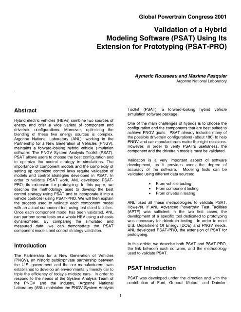
Chrysler for the Partnership for a New Generation <strong>of</strong>Vehicle (PNGV).Forward-Looking Model<strong>PSAT</strong> is a powerful modeling tool that allows users torealistically evaluate not only fuel consumption andexhaust emissions for more than 20 different cycles, butalso vehicle performances. Moreover, one <strong>of</strong> the mostimportant characteristics <strong>of</strong> <strong>PSAT</strong> is that it is a forwardlookingmodel, meaning <strong>PSAT</strong> allows users to modelreality with real commands. <strong>PSAT</strong> is called a commandbasedmodel. In fact, we estimate the necessary wheeltorque to achieve the desired speed by sending realcommands to the different components, such as throttlefor engine, displacement for clutch, gear number fortransmission, or mechanical braking for wheels. In away, we model a driver who follows a pre-defined speedcycle. Moreover, as components react to the commandsas in reality, we can implement advanced componentmodels, take into account transient effects (such asengine starting, clutch engagement/disengagement, orshifting) or develop realistic control strategies.Conversely, in a backward-looking model, componentscannot be controlled as in reality. The desired vehiclespeed goes from the vehicle model back to the engine t<strong>of</strong>inally determine how each component should be usedto follow the speed cycle. Because <strong>of</strong> this modelorganization, quasi-steady models can only be usedand, consequently, transient effects cannot be taken intoaccount. Therefore, an accurate control application isnot possible with a backward-looking model.Looking toward the future, to be able to study transienteffects and the interaction between components withaccurate control commands, ANL developed a forwardlookingmodel: <strong>PSAT</strong>.allowing users to choose the most appropriateconfiguration related to their requirements.<strong>PSAT</strong> flexibility and reusability is based upon severalcharacteristics, as described below.Components ModelsOrganization FormatIn order to easily exchange the models and implementnew ones, a common format, based on Bond Graph, isused between the input/output <strong>of</strong> the power ports, asshown in Figure 1. The first ports are used for theinformation:• Input: components commands (i.e., on/<strong>of</strong>fengine, gear number, etc…)• Output (sensors): simulated measures(i.e., torque, rotational speed, current, voltage,etc.)The second ports carry the effort (i.e., voltage, torque),and the last ones the flow (i.e., current, speed).EffortFlowCommand fromController (PTC)MODELInfo to PTCEffortFlowFlexibility And ReusabilityIn a world <strong>of</strong> growing competitiveness, the role <strong>of</strong>simulation in vehicle development is constantlyincreasing. Because <strong>of</strong> the number <strong>of</strong> possible hybridarchitectures, the development <strong>of</strong> this new generation <strong>of</strong>vehicles will require accurate, flexible simulation tools.Such a simulation program is necessary to quicklynarrow the technology focus <strong>of</strong> the PNGV to thoseconfigurations and components that are best suited forachieving these goals. Therefore, the simulation shouldbe flexible enough to encompass the wide variety <strong>of</strong>components and drivetrain configurations.<strong>PSAT</strong> includes more than 150 predefined configurations,including conventional vehicles, parallel hybrids, serieshybrids, fuel cell hybrids and power split hybrids. Usersalso have the possibility to choose two, four, and twotimes two-wheel drive. Such a capability is only possibleby building all these drivetrain configurations accordingto user’s inputs and component models from the libraries2 Effort = Torque, Voltage… Flow = Speed, Current… Fig. 1: Global Formalism for the Input/Output <strong>of</strong> theModels <strong>Using</strong> Bond GraphUse <strong>of</strong> Library –To ensure that the models we are using are the lastones changed or are not modified, we decided to use alibrary in which all the models are saved. Librariesenable users to copy blocks into their models fromexternal libraries and automatically update the copiedblocks when the source blocks change.
Use <strong>of</strong> Masks – based upon the component (e.g., mc formotor/controller). In fact:<strong>Hybrid</strong> electric drivetrain configurations can be verydifferent from one another and also be rapidly complex.Often, one component can be used several times, suchas the electric motor for the Precept from GeneralMotors or the Prius from Toyota. In order to solve theproblem <strong>of</strong> versioning, we decided to mask the differentcomponent models, allowing us to reuse the samemodel several times, as shown in Figure 2.••••••The component model name is defined as‘compo’_cm (e.g., mc_cm)The initialization file is ‘compo’_init,The scaling file is ‘compo’_scale,The calculation file is ‘compo’_calc,The parameter used to choose whether we scale isgui_scale_’compo’,The parameter used to scale the component isUse <strong>of</strong> GOTO-FROM Format –gui_’compo’,To simplify the model, we decided to use the GOTO-FROM format. As far as the models are concerned, allthe GOTO-FROM blocks are local and located at theupper level <strong>of</strong> the model (no blocks are located in thesubsystems). To facilitate the work for Hardware In theLoop (HIL) (Control Desk access to the parameters andvariables by using the Tags), the name <strong>of</strong> the Tags aredefined using specific rules.Use <strong>of</strong> common nomenclature for variable names –<strong>PSAT</strong> names have been parameterized and followspecific rules. At the component level, all the variablesand parameters also follow established rules and arenamed according to the component and the type <strong>of</strong> datathey represent. At the s<strong>of</strong>tware level, the names areExample <strong>of</strong> Drivetrain Configuration - ParallelConfiguration Example –As an example, it is interesting to look at a <strong>PSAT</strong> parallelconfiguration model to understand the benefit <strong>of</strong> using alibrary and standard format (Figure 3).The driver output is a torque demand at the wheels,which is proportional to an accelerator or brake pedalcommand. This demand is sent to the powertraincontroller, which decides how each component <strong>of</strong> thedrivetrain should operate. Indeed, we make a choiceconcerning the blending between the different energysources, such as when and how to start the engine orshift a gear.The same model can be used for differentcomponentsFig. 2: Use <strong>of</strong> Mask Allows Reuse <strong>of</strong> the Same Models3
Figure 3: <strong>PSAT</strong> single shaft parallel hybridThe powertrain controller will send specific commands toeach drivetrain component: torque to the electric motor,throttle to the engine, displacement to the clutch, gearnumber to the transmission, and mechanical brake tothe wheel.Then, the mechanical power from the engine and theelectrical power from the motor via the battery aresummed. And in fact, both mechanical and electricalpowers are used to propel the vehicle.As alreadymentioned, each component block has three inputs andthree outputs and is linked to the library. Thesecomponents models are reusable and perform as inreality. We can also use these components for controldevelopment: the first input will be the command, andthe first output will be the information from the sensors.Powertrain Controller Models<strong>PSAT</strong> powertrain controllers, in charge <strong>of</strong> commandingthe different components, have a generic structurecommon to all configurations. By using the acceleratorpedal and the information (sensors) coming from thecomponent models, we evaluate the constraints <strong>of</strong> thesystem, such as the maximum available torque <strong>of</strong> theengine. We then take those limits into account to definethe optimized control strategy, which allows us to usethe powertrain components to minimize fuelconsumption and emissions. Finally, we take thetransients into account by defining the actions necessaryto satisfy the control strategy demands. For instance, if4 the control strategy decided to shift gear with a manualtransmission, we must cut <strong>of</strong>f the engine ignition,declutch, engage the neutral gear, engage the new gear,clutch, and inject once again. These steps must happensuccessively and lead to a modification <strong>of</strong> the demandspreviously sent by the control strategy.Within <strong>PSAT</strong> powertrain controller, different strategiescan be selected within a particular powertrain model.Indeed, as the strategy has an important impact on thefuel consumption, it is interesting to switch betweendifferent control strategies for comparison. For instance,the engine start can be based on different parameters,such as vehicle speed, power demand, torque demand,level <strong>of</strong> State Of Charge (SOC) or a combination <strong>of</strong>these. In order to evaluate the impact <strong>of</strong> these differentstrategies, we can select and compare them using thesame components models. This also allows us to easilyimplement new strategies.<strong>PSAT</strong>-PRO Introduction<strong>PSAT</strong>-PRO: generic and reusable<strong>PSAT</strong>-PRO must be generic and reusable enough tocontrol any kind <strong>of</strong> configurations (conventional orhybrids). The structure <strong>of</strong> <strong>PSAT</strong>-PRO has been
developed to be the same with any configuration. Threemain blocks compose <strong>PSAT</strong>-PRO model:• Test procedure,• Control command system,• Physical system.Users can define commands to apply to the system inthe test procedure. Then, the test procedure sends thecommand bus to the control command system, which isin charge to effectively apply those commands to eachcomponent in accordance with the system constraints.The physical system represents the vehicle modelcomposed by the components models, either Digital toAnalog (DAC) and Analog to Digital Converters (ADC),depending on the process phase (simulation or rapidprototyping). In fact, the vehicle model should reactexactly as the actual system as we send the samecommands. Differences come from the converters: whenthe user controls the actual system, the commands mustbe converted to communicate with the actuatorscontrollers. The data sent by the sensors must betranslated in a digital format to be able to use themeasures. Figure 4 shows the three main blocks <strong>of</strong> the<strong>PSAT</strong>-PRO model.The command bus goes from the test procedure,through the control command system, to the physicalsystem. The physical system reacts by sending themeasure bus to the control command system throughthe test procedure. <strong>Using</strong> ControlDesk, we have accessto the commands and the measures in only one block:the test procedure.The test procedureThe command bus is created in the test procedure, andthe measure bus is received. For each actuator, wehave a command, or several, depending on the modeused. For instance, a motor can be controlled in torqueor in speed mode if a speed regulation exists in themotor controller. So in this case, we create a torquecommand, a speed command, and a mode command inthe bus command. This bus command will be modifiedlater in the control command system to process theinformation.The control command systemThe control command system is the brain <strong>of</strong> the system,as each component control is decided here. It includesseveral functions:1) As the command and the measure buses go throughthe control command system, a function to continuouslycheck if measures reach commands has beendeveloped. If not, a warning is sent. With this function,we also check if the commands are possible (i.e., if theuser asks commands in accordance with thecomponents constraints). We can also check if the5 measures are not above the constraints (i.e., overspeed, over heat, etc.). In each possible case, we senda warning to the emergency function, which modifies thecommands in order to follow the right emergencyprocedure corresponding to the warning.2) The components constraints are calculated in theconstraints function, which takes into account eachcomponent <strong>of</strong> the power train and their interaction. Forinstance, the engine constraints can affect the motorrange depending <strong>of</strong> the gear ratio.3) A parameter function has been developed in order tocalculate the values needed but not measured or notmeasurable, such as the SOC.4) The control command system also includes afunction, which is in charge <strong>of</strong> defining the systemstatus, such as the motor’s direction.5) To decide how to satisfy the users’ demands in anoptimal way, we include the <strong>PSAT</strong> control strategy andtransient block as a function. The details on how toincorporate the control strategy explained later in thispaper.6) Before sending the commands, a saturation functionis in charge to limit the commands with the appropriateconstraints to ensure we always send acceptablecommands.The physical systemThe physical system receives the commands from thecontrol command system. The physical system model isbuilt using the <strong>PSAT</strong> structure and components modelsdescribed previously. When users want to use RapidPrototyping, the components models are replaced by theactual components, and a DAC and ADC are added.The physical system is shown in Figure 5. The buscommand is converted to send analog values to theactuators controllers through the dSPACE boardoutputs. The converted analog values coming from thedSPACE board inputs create the measures bus.From <strong>PSAT</strong> <strong>Modeling</strong> to <strong>PSAT</strong>_PRO Prototyping– a Generic ProcessAs <strong>PSAT</strong> is a forward-looking model, it is well suited toaccurately control the powertrain components.Moreover, because <strong>PSAT</strong> includes many configurations,users can develop their own control strategies for thespecific powertrain studied. Then, <strong>PSAT</strong>-PRO controls<strong>of</strong>tware allows us to download it in the vehiclecontroller. In this section, we describe in detail the threesteps necessary to reach this goal:• Simulation• Hardware In the Loop (HIL)• Rapid prototyping
Fig. 4: <strong>PSAT</strong>-PRO model and real physical systemscmd_signal_conditionningmes_signal_conditionning1Command Bus1Measures BusFig. 5: <strong>PSAT</strong>-PRO Physical System for Rapid Prototyping6
The purpose <strong>of</strong> <strong>PSAT</strong>-PRO is to allow users to go frommodeling, using <strong>PSAT</strong>, to prototyping, for any kind <strong>of</strong>vehicle or configuration. As with <strong>PSAT</strong>, <strong>PSAT</strong>-PROmust also be generic and reusable. Moreover, boths<strong>of</strong>twares must be linked to directly integrate the controlstrategy optimized in <strong>PSAT</strong>. Finally, we explain how thecomparison between the test data and the simulationresults can provide modeling validation andimprovement.A Process In Three StepsSimulation<strong>Using</strong> <strong>PSAT</strong>, we simulate the vehicle performance inorder to define the best drivetrain, select the appropriatecomponent technology and size, and develop the controlstrategy in accordance with the specifications. In <strong>PSAT</strong>-PRO, we model the physical system exactly as in reallife, including signal conditioning or a dynamometermodel for testing the powertrain on a test stand. Thegoal is here to minimize the modifications <strong>of</strong> <strong>PSAT</strong>component models to later facilitate the validation <strong>of</strong>those models. To verify the performance <strong>of</strong> the physicalsystem model that will be later be controlled on a benchor in a vehicle, a simulation phase must be performed,following the test procedure decided upon earlier.Hardware In the LoopOnce the <strong>PSAT</strong>-PRO model has been verified, Real-Time Workshop is used to automatically generate Ccode from Simulink block diagrams. Generated code isapplied in a variety <strong>of</strong> applications such as real-timeembedded control, DSP design, HIL, and stand-alonesimulation. The generated C code is portable and runson many floating-point processors. Once the <strong>PSAT</strong>-PRO model is downloaded on the processor, we canapply commands, observe in real time, and capture datafrom sensors using ControlDesk. ControlDesk isdSPACE's new experiment s<strong>of</strong>tware, which providestools for controlling, monitoring, and automating realtimeexperiments. The development <strong>of</strong> controllers isthen more effective.In this phase, we verify the test procedure in real time inorder to finish the control checking. In fact, the control isdownloaded in a microcontroller running at 10 Hz andthe physical system in another microcontroller runningfaster. The two systems communicate together exactlyas in reality using the appropriate signals. The fastermicrocontroller has to exactly represent, in real time, theactual system behavior. The control strategy can thenbe checked in a safe way.Rapid PrototypingAfter control is checked both in simulation and in realtime, the last phase consists <strong>of</strong> replacing the modeledcomponent with the real ones from the test stand or the7 car. <strong>Using</strong> ControlDesk, <strong>PSAT</strong>-PRO proposes agraphical user interface to control each component <strong>of</strong> ahybrid powertrain. Figure 6 provides an example <strong>of</strong> the<strong>PSAT</strong>-PRO ControlDesk layout.<strong>PSAT</strong>-PRO is linked to <strong>PSAT</strong>The Physical SystemThe physical system model is built using the <strong>PSAT</strong>components models library. In fact, libraries enableusers to copy blocks into their models from externallibraries and automatically update the copied blockswhen the source blocks change. Libraries allow users toaccess models provided by others (such as <strong>PSAT</strong>) toensure that their models automatically include the mostrecent versions <strong>of</strong> these blocks. By using similarcomponent models as in <strong>PSAT</strong>, we then facilitate thevalidation process <strong>of</strong> the different models.The Control StrategyAs described before, the <strong>PSAT</strong>-PRO control commandsystem includes several functions. One function is thecontrol strategy developed in <strong>PSAT</strong>. As both s<strong>of</strong>twaresuse the same structure, the <strong>PSAT</strong> control strategy is“plug and play”. We simply need to copy the controlstrategy and the transient block previously developed forsimulation purposes into the specific control that willlater be used for HIL or rapid prototyping. It is veryinteresting to develop a control strategy based onsimulation and to test its efficiency in real life. Onceagain, using this methodology, we facilitate thevalidation process.As <strong>PSAT</strong>-PRO is linked to <strong>PSAT</strong>, it becomes easy tointegrate any <strong>PSAT</strong> control strategy in the <strong>PSAT</strong>-PROcontrol command system. <strong>PSAT</strong>-PRO allows users todirectly integrate the control strategy optimized in <strong>PSAT</strong>for any kind <strong>of</strong> configurations.Calibration ProcessSimulation Results And MeasuresThe calibration process is used to improve the physicalsystem model accuracy. The principle is simple: as weuse the same test procedure for each step (Simulation,HIL, rapid prototyping), the physical system, real orsimulated, should react exactly the same way. In onehand we have the simulation results, and in the otherhand, we have the measures. In order to compare theresults and to analyze the differences, the measurescollected are transformed in the right format and thenusing graphical tools, differences are analyzed andexplained.
8 Figure 6: Example <strong>of</strong> <strong>PSAT</strong>-PRO ControlDesk’s Layout
A Closed Loop ProcessIf necessary, the model is modified in order to improveits accuracy and to be closer to reality. After themodifications, we rerun the test procedure in simulationand compare again the results and the measures. Thisloop can be performed several times depending on theprecision level required.Physical System Model CalibrationWhen we perform a test in the rapid prototyping phase,we save the commands from the test procedure. So, insimulation, we are able to apply these commands to thephysical system model. In this way, we are sure thedifferences can come only from the physical systemmodel, as we use the same control command system.Data AcquisitionWith the ControlDesk data management tool, we captureall the data used on the model. This means we haveaccess to the commands bus and the measures bus.For each test performed, we are able to save a file in aMatlab format containing the measures and thecommands. We then integrate the data in our Simulinkmodel to perform the same test in Simulation. Then, weuse a program based on graphical analysis to comparethe results. So, we are able to compare the differencesbetween the simulation results and the rapid prototypingresults (measures).ConclusionBecause <strong>of</strong> the number <strong>of</strong> possible hybrid architectures,the development <strong>of</strong> this new generation <strong>of</strong> vehicles willrequire simulation tools. Moreover, the complexity <strong>of</strong> thisnew generation <strong>of</strong> vehicles imposes the use <strong>of</strong> anintelligent control. The PNGV System Analysis Toolkit(<strong>PSAT</strong>) allows users to choose the appropriateconfiguration, component sizes, and technology and tooptimize the control strategy in simulation for a widerange <strong>of</strong> HEVs. But to control the real vehicle using thisoptimized control strategy, a more complex controlcommand system is needed. The number <strong>of</strong>components to control increases the control complexity.That’s why three steps are necessary to complete theintegration <strong>of</strong> the control in the vehicle. <strong>PSAT</strong> and<strong>PSAT</strong>-PRO tools <strong>of</strong>fer users the unique possibility todevelop their own control strategy, optimize it, integrateit in a prototype, perform tests, calibrate the model, andevaluate the efficiency <strong>of</strong> their control strategy.Moreover, as <strong>PSAT</strong> and <strong>PSAT</strong>-PRO share the sameorganization and models, this process is reusable andcan be applied to any kind <strong>of</strong> vehicles.AcknowledgmentsThe authors are grateful for the support given by theU.S. Department <strong>of</strong> Energy (DOE) for funding our work,the Partnership for a New Generation <strong>of</strong> Vehicles(PNGV) and USCAR for their support and guidance.ReferencesControlDesk 2.0. Experiment Guide. DSPACE GmbH.DeCharentenay, F.; Delhom, M.; and Rault, A.. 1996.Seamless Mechatronic Design <strong>of</strong> an Electric VehiclePowertrain Convergence 96, pp 413-421.Karnopp, D.; Margolis, D.; and Rosenberg R. 1990.System Dynamics: A Unified Approach, 2 nd ed. JohnWiley & Sons, Inc., New York.Matlab V5.3.1/Simulink V3.0 Users Guide. TheMathworks, Inc.Rimaux, S., Delhom, M., Combes, E., and Rault, A.1998. <strong>Hybrid</strong> Vehicle Powertrain: <strong>Modeling</strong> and Control.Rousseau, A., and Pasquier, M., “<strong>Validation</strong> Process<strong>of</strong> a System Analysis Model: <strong>PSAT</strong>”. SAE Paper 01-P183.Rousseau, A., and Larsen, R., 2000, Simulation and<strong>Validation</strong> <strong>of</strong> <strong>Hybrid</strong> Electric Vehicles <strong>Using</strong> <strong>PSAT</strong>. GPCConference, Detroit, Mich., June 6-8.ContactsAymeric RousseauResearch EngineerCenter for Transportation Research(630) 252-7261E-mail: arousseau@anl.govMaxime PasquierResearch EngineerEnergy Systems Division(630) 252-9717E-mail: mpasquier@anl.gov9