HYPERSTATIC SENSOR INSTALLATION MANUAL - Thor Guard, Inc.
HYPERSTATIC SENSOR INSTALLATION MANUAL - Thor Guard, Inc.
HYPERSTATIC SENSOR INSTALLATION MANUAL - Thor Guard, Inc.

Create successful ePaper yourself
Turn your PDF publications into a flip-book with our unique Google optimized e-Paper software.
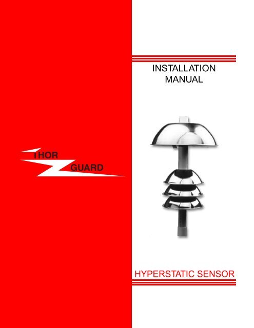
<strong>INSTALLATION</strong><br />
<strong>MANUAL</strong><br />
<strong>HYPERSTATIC</strong> <strong>SENSOR</strong>
<strong>HYPERSTATIC</strong> <strong>SENSOR</strong> <strong>INSTALLATION</strong><br />
Choosing the Sensor Location<br />
The location of the Sensor will be dependent upon the desired location of the THOR GUARD<br />
console, the type of existing roofing material, the design of the roof, and the proximity of other<br />
equipment that may adversely affect the performance of the system. If a roof location is not<br />
possible, the Sensor may be mounted on a post or pole, as long as it has a clear view of the<br />
atmosphere. The following should be considered during the pre-installation survey as to locating<br />
the Sensor:<br />
· As close to the console as possible (200’ Max.).<br />
· At least 10’-15’ from lightning rods.<br />
· At least 15’-20’ from air conditioning units, vents, fans, etc.<br />
· At least 20’-30’ from other antennas; e.g. TV. VHF, etc.<br />
· As far from the trees as possible to discourage birds and spiders.<br />
· Outside a 30-degree angle from light poles or trees (trees absorb electrostatic field).<br />
· As far as possible from electric charger units or large transformers.<br />
· A metal roof can steal the energy from the Sensor so call the factory for advice.<br />
· High enough so that curious hands cannot inadvertently touch the Hyperstatic Plate<br />
thereby setting off the system.<br />
· MAKE SURE THAT ANY MAST OR TRIPOD UTILIZED TO MOUNT THE <strong>SENSOR</strong> IS<br />
NOT GROUNDED.<br />
· <strong>SENSOR</strong> MUST BE ACCESSIBLE FOR REGULAR CLEANING.<br />
Running the T riaxial Cable<br />
You have been supplied with a predetermined length of special triaxial cable which should accommodate<br />
your installation. Hopefully the pre-installation survey correctly estimated your needs. The<br />
path available for the cable will also dictate the final location of the Sensor and Console. Apart<br />
from avoiding the obvious obstacles, attention should be given to the following:<br />
· The cable does not carry any AC power, so in most instances it won’t be necessary to<br />
enclose it in conduit. However, local ordinances should be reviewed and requirements<br />
adhered to, always.<br />
· When routing the cable, do not parallel lightning rod grounding wires.<br />
· Avoid sharp bends, metal edges, or anything that might tear outer jacket.<br />
· Conceal and secure as much as possible.<br />
· Avoid pulling too tightly and stretching the cable.<br />
· Take care to NOT damage connector by forcing it through tight places.<br />
NOTE: IF YOU ALSO PLAN TO INSTALL A VOICE OF THOR ALARM SYSTEM IT WOULD<br />
BE ADVISABLE TO ALSO RUN THE COMM-LINK CABLE (6 COND.) TO THE ROOF AT THE<br />
SAME TIME YOU RUN THE TRIAXIAL CABLE.<br />
<strong>HYPERSTATIC</strong> <strong>SENSOR</strong> <strong>INSTALLATION</strong><br />
7/99<br />
1
<strong>HYPERSTATIC</strong> <strong>SENSOR</strong> <strong>INSTALLATION</strong><br />
Mounting Instructions<br />
1. Choose the location and run the sensor cable (above).<br />
2. Select the mounting technique and prepare for installation (above).<br />
3. If mounting on a 1” galvanized pipe glue the enclosed reducer to sensor bottom.<br />
4. CABLE: You have been provided with a predetermined length of triaxial cable. If this cable<br />
needs to be spliced, refer to page 9 (Sensor cable splice).<br />
5. Carefully thread the sensor onto the pipe stub and tighten.<br />
6. Coil any excess cable as a service loop and tie-wrap to something solid.<br />
7. After the THOR GUARD console is installed, and the sensor cable is attached, refer to<br />
testing the sensor in the Operators Manual.<br />
Maintenance and Cleaning<br />
Clean the Sensor on the roof of all dirt that may have accumulated on all of the white plastic PVC<br />
parts, any cobwebs between the large stainless steel dome (on top) and round plate, and any<br />
excess dirt on the plate, itself. This should be accomplished with ONLY clean paper towels (dampen<br />
only with water), as cleaning rags may contain solutions that will contaminate the surfaces.<br />
Then dry the area cleaned with other paper towels. The large dome may be slightly tilted to allow<br />
your hand entry, but care should be taken to avoid damage to any of the small, wire connections.<br />
NOTE: REGULAR CLEANING OF THE <strong>SENSOR</strong> WILL MINIMIZE FAILURES. SOME<br />
ENVIRONMENTS WILL NECESSITATE MORE CLEANING.<br />
7/99<br />
1. Disconnect the power to the THOR GUARD Console so the cleaning does not produce a<br />
false reading and inadvertently activate the external alarms.<br />
2. Return to the THOR GUARD Console, reconnect power and push the TEST button to<br />
verify operation.<br />
<strong>SENSOR</strong> MUST BE ACCESSIBLE FOR REGULAR CLEANING<br />
LARGE DOME<br />
<strong>HYPERSTATIC</strong><br />
PLATE<br />
CABLE<br />
<strong>SENSOR</strong> ASSEMBLY<br />
3<br />
RUBBER WASHER<br />
AREAS TO CLEAN (PVC)<br />
Use clean damp paper towels,<br />
clean sensor, allow to dry
The Voice of THOR external air horn alarm warning system may include the following components:<br />
7/99<br />
1. Master Alarm Control (MAC) or VOT Base Console (VOT-BC), with a connector cable to<br />
complete the link with the THOR GUARD Console.<br />
2. Specified length of Comm-Link cable: Penn #3021, 6 cond., 18 awg, Shielded Type CM<br />
or CL3 75C[UL], or equivalent to link Base Console with Base Driver.<br />
3. VOT Base Driver (VOT-BD) including transmitter, battery, and transmitting antenna/strobe<br />
light kit.<br />
4. VOT Horn Clusters (VOT-HC) with specified length of compressor power cable.<br />
5. VOT Remotes (VOT-RC ) including receiver, battery, and receiving antenna/strobe light kit.<br />
Installation<br />
Master Alarm Control (VOT-MAC)<br />
1. Position the MAC on top of the THOR GUARD console but DO NOT connect the power<br />
adapter to AC as yet. It would be a good idea to now refer to the MAC Operations Manual!<br />
2. Plug the VOT/THOR GUARD Connector Cable into the output of the<br />
THOR GUARD (5 pin) and the input of the MAC (6 pin).<br />
3. If you did not run the Comm-Link before (with the Sensor cable) it needs to be run now.<br />
4. Connect “like” colored wires to pigtail with connector as provided (solder and tape<br />
securely).<br />
5. Apply power and make Menu selections ( see MAC Operations Manual).<br />
4
VOT Base Driver (VOT -BD) & Hor n Cluster (VOT -HC)<br />
The L150 or the VOTMAC is used to control the VOTBD. You have been supplied a “pigtail” cable that<br />
connects to the rear of the console in the location VOTBD. Solder & tape each wire from the Comm-Link<br />
cable to the pigtail. The VOTBD must be installed before connecting Comm-Link cable to the console.<br />
The VOT Base Driver controls the base VOT-HC and contains the RF Computer/Transmitter to<br />
transmit to the VOT- R C ’s. The Base should be located within the lengths of the cable supplied to the Horn<br />
Cluster and to the RF antenna. Excess compressor cable should be removed. Do not alter the RF cable<br />
length. The RF antenna may be mounted on the same mast (pipe) that holds the base VOT-HC or, if<br />
utilized, one of the tripod legs, or mounted separately. The standard length for both the compressor cable<br />
and the RF cable is 18Ft. Cable lengths of 40Ft. are available for both RF and compressor cable. When<br />
securing cables, if using staples, do not attach tightly, as damage may occur.<br />
N O T E: You will need to access the VOT-BD box to check/change the battery and the<br />
Computer/Transmitter so it needs to be accessible.<br />
1. The positioning of the Base Horn Cluster to achieve maximum coverage will probably be the<br />
controlling factor (remember, sound rises, so higher is not really better). The individual horns<br />
may be adjusted to optimize coverage.<br />
2. Determine the type of mounting hardware required for the location selected (above) as well as<br />
the length of 1” pipe to be utilized to mount the Horn Cluster.<br />
3. Screw the Horn Cluster onto the 1” pipe after feeding the attached compressor power cable<br />
down the pipe.<br />
4. Mount the Base Antenna (if there are to be remotes) to the 1” pipe or otherwise, per the<br />
instructions in kit.<br />
5. Attach the entire assembly to the desired mounting location. Allow for a service loop leaving<br />
the pipe.<br />
6. Mount the VOT-BD box. The Comm-Link cable from the VOT-MAC below should already be<br />
available at this location. Remove 1Ft. gray insulation from this cable. Cut off brown wire.<br />
7. Run Compressor Power Cable (18Ft. provided) and the VOT-MAC Comm-Link Cable into the<br />
VOT-BD box through inputs (bottom of box) and secure the RF cable connector to the<br />
connector provided outside. Insure the RF connector is correctly seated and tighten firmly.<br />
8. Solder and tape Comm-Link White, Blue, and Green wire to the matching colors of the<br />
three-conductor right angle plug provided. Then plug right angle phone jack into the slot on the<br />
left side of the Transmitter.<br />
9 . Insert the Red and Black battery charger wires to the Relay Bracket in the appropriate slots marked<br />
“solar”.<br />
10. Insert Compressor Power Cable ends into marked slots on Relay Bracket; match colors as<br />
marked.<br />
11.Horn Set 1 (Red + Black -), Horn Set 2 (Orange + Blue -).<br />
12. If supplied, attach strobe light to the top of the Relay Bracket where labeled. Observe<br />
correct colors.<br />
13.Connect Red (+) lead to 12-volt battery. Insure tight connection.<br />
14. R e t u rn to the MAC and apply power. Then re t u rn to Base Driver and turn on the<br />
Computer/Transmitter by pushing the blue side button on the right side of the transmitter. The<br />
Center Bar on the display will blink if correctly connected. A letter “E” blinking will indicate a<br />
connection problem. Check your wire splice, is right angle plugged in firmly? If you then press<br />
and hold the “Horn Test” (black button located on transmitter) for 5 seconds, the horns should<br />
sound. If a strobe light is attached, the light will turn on. Release button to stop test. You may<br />
also press the blue button on the Relay Bracket to perform the same test.<br />
15.After Remotes are installed test the entire system (Red Alert), and re-test regularly!<br />
7/99<br />
5
VOT Base<br />
VOTBD<br />
Solar VOTRC or<br />
Transmitter VOTBC<br />
1. Battery: The Black (-) cable will arrive attached. Connect Red (+) cable to the battery.<br />
2. Phono Jack: Connect to corresponding white, blue & green wires on comm-link cable.<br />
3. Relay Board: Connect the power cables for the horn cluster as marked on board, the<br />
red (+) and black (-) 12V power wires from the comm-link cable, and the green power plug.<br />
Turn power on by depressing blue switch on the Transmitter. When you apply power the LED<br />
will display the coding for your RF signal then return to a space bar (-) in the center of the<br />
display. When sending RF: #1 = All Clear; #2 = Red Alert<br />
3. Green Power Plug: This cable connects the transmitter to the Relay Board. The function of<br />
each wire is: RED - +12VDC Power, BLACK - Ground, WHITE – Strobe Enable (low),<br />
Green – Horn Enable (low)<br />
4. Install antenna and connect cable to bottom of the box.<br />
PROBLEM: Green Power Plug is in place but the Transmitter will not power up: (a.) Engage<br />
On/Off switch once or twice to insure that nobody has turned the transmitter off. (b.) Check battery<br />
power with voltmeter. Also check to insure outside power is to the box (red & black wires on<br />
solar connection) and that the battery is being properly charged (Red light on Relay Bracket board<br />
is on. (c.) Call Service.<br />
PROBLEM: Transmitter seems to be transmitting the signal, but the horns don’t sound: (a.) Do<br />
the horns sound when you push the Horn Test button on the transmitter (hold down for 5 seconds)?<br />
(b.) Do you hear a clicking sound from the Horn Bracket indicating the relays are engaging<br />
when you depress the Horn Test button? If not: (1.) Does your battery maintain at least 10 volts<br />
when you push the Horn Test button while measuring the battery leads with a voltmeter? No?,<br />
then replace it.<br />
PROBLEM: Transmitter is not transmitting: (a.) Check battery and verify power to the transmitter<br />
and that the LED displays a bar (-). (Note: If phono jack RF link to base is not in place then the<br />
LED will display an “E”, indicating no connection to base). (b.) Check all antenna leads (bottom of<br />
box and on left side of transmitter) to insure proper connection. (c.) Run through other checks<br />
(above) and if it still won’t operate call Service.<br />
PROBLEM: Horns do not complete cycle: Battery is probably low. Please check with voltmeter.<br />
7/99<br />
6
VOT Remote (VOT -RC) & Hor n Cluster (VOT -HC)<br />
Each VOT Remote should be located where the horns are in the clear and will offer the best<br />
coverage, and where there is a reasonable “line of site” for the RF antenna to the Base<br />
(VOT-BD) antenna. To insure consistent performance, install the antenna so that it is not located<br />
under trees because leaves absorb RF signal when wet.<br />
The installation should be performed in the same manner as the Base VOT-HC and the VOT-BD,<br />
with an effort to make the Compressor Power cable between the VOT-RC and the VOT-HC as<br />
short as possible. When securing cables, if using staples, do not attach tightly to RF cable,<br />
damage may occur.<br />
7/99<br />
1. A post mount (see enclosed diagram) or pipe mount is the most efficient and flexible<br />
manner for mounting a remote. If mounting on a shelter or rest station a tripod or standoff<br />
will normally be utilized (see mounting the Sensor). Follow any electrical codes that are<br />
required.<br />
2. The remote will be powered by AC (VOTRCE has a 5Ft, 3 cond. power cable) or a solar<br />
panel (VOTRCS).<br />
3. If solar is used, position 20W solar panel on mounting bracket and face South. Position<br />
panel so that the power cable will pass through the left black strain relief on the box and<br />
connect to top of the relay board.<br />
4. “Dedicated” AC is not a requirement because this is a 12 volt system and draws very little<br />
amperage. But a reliable source of AC is important; otherwise the battery will lose charge<br />
and not activate the horns. Satellite sprinkler control locations are often utilized as the<br />
source for power. For safety, the power cable should be connected directly to a 115AC<br />
electrical outlet. For solar remote, insert wire red & black wires into marked slots on top of<br />
relay board. (Solar is preferred for reduced maintenance).<br />
5. Attach R F cable, Insert Compressor power cable Install the VOT-HC and RF antenna as with<br />
the instructions for the Base Driver horn cluster (above) steps 1 - 5. The only exception is<br />
that step #8 will obviously not be necessary because there is no Comm-Link cable.<br />
Connect Red (+) cable to the battery.<br />
6. If supplied, connect strobe light to top of relay board, using left black strain relief. Tighten<br />
strain relief.<br />
7. If remote is powered by electric, turn “ON” AC switch, check for Green light next to the<br />
switch to come on.<br />
7
7/99<br />
8. Turn “ON” Receiver switch and watch for the proper cycle of the system monitoring LED.<br />
This will first display the RF code, and then you should see a blinking bar (-) in the center.<br />
A Red light on the relay board will be on when the battery is charging.<br />
9. You may test the horns by pressing the black button on the Receiver and holding for 5<br />
seconds, or instantly by pushing the blue button on the Relay Board. If attached, the strobe<br />
light will come on.<br />
VOTRC Solar<br />
SOLAR POWER HOOKUP<br />
8<br />
VOTRC Solar PC Board
7/99<br />
VOTRC<br />
Electric Remote<br />
1. Battery: The Black (-) cable will arrive attached. Connect Red (+) cable to the battery.<br />
2. Relay Board: Connect the power cables for the horn cluster as marked on board. Connect<br />
strobe wires and solar panel wires as required. Press blue “horn test” button on relay<br />
board.<br />
3. Turn power on by depressing blue switch on the receiver.<br />
When you apply power, the LED will display the coding for your RF signal then return to a<br />
blinking space bar (-) in the center of the display. When receiving RF: #1 = All Clear;<br />
#2 = Red Alert. During the MAC “RF” test, the numbers “989” should be displayed which<br />
indicates that the receiver is receiving the transmission without sounding horns or light.<br />
4. Green Power Plug: This cable connects the receiver to the relay board. The function of<br />
each wire is:<br />
RED - +12VDC Power, BLACK – Ground, WHITE – Strobe Enable (low), Green – Horn<br />
Enable (low).<br />
9<br />
VOTRC<br />
Electric PC Board
PROBLEM: Green Power Plug is in place but the Receiver will not power up: (a.) Engage Blue<br />
On/Off switch once or twice to insure that nobody has turned the receiver off. (b.) Check battery<br />
power with voltmeter. Also check to insure outside power is to the box (either solar or local AC)<br />
and that the battery is being properly charged. (c.) Place positive voltmeter lead on Power Plug<br />
Red, Negative on Black. Should show approx. 12 volts. (d.) Call Service for technical support.<br />
PROBLEM: Receiver seems to be receiving the transmitted signal, (display has a blinking<br />
number) but the horns don’t sound: (a.) Do the horns sound when you push the blue horn test<br />
button on the relay board? (b.) Do you hear a clicking sound from the Horn Bracket indicating the<br />
relays are engaging when you depress the Horn Test button? If not: (1.) Does your battery<br />
maintain at least 10 volts when you push the Horn Test button while measuring the battery leads<br />
with a voltmeter? No?, then replace it. (c.) Apply horn cable to the battery directly, checking each<br />
set of horns, Horn Set 1(Red +, Black -), Horn Set 2 (Orange +, Blue -). Replace the Horn cluster<br />
if weak or defective horn set. If there are multiple remotes, exchange receiver with a known good<br />
Remote, otherwise request a replacement.<br />
PROBLEM: Receiver is not receiving the transmitted signal or does not work consistently:<br />
(a) Make certain antenna is clear from tress. (b.) Check all antenna leads (bottom of box and<br />
on left side of receiver) for proper connection. Check battery & verify power to the receiver, and<br />
correct display. (Note: You can switch Receiver with another one that you know is working to<br />
verify antenna operation.)<br />
PROBLEM: Horns do not complete cycle: Battery is probably low. Please check with voltmeter.<br />
7/99<br />
10
VOTBDNH & VOTRCNH<br />
The VOTBDNH is for locations where there are no base horns. There is 40Ft. of RF cable<br />
included.<br />
Attach the box to the sensor mounting bracket if possible. When securing cable, if using<br />
staples, do not attach tightly, as damage may occur. Do not alter the RF cable length.<br />
VOTBDNH<br />
1. Mount the box to the selected location using “U” bolts or lag screws.<br />
2. After the antenna has been mounted at the selected location, remove the black grommet<br />
from the box. Place the cable inside the grommet and reattach to box. Secure the RF<br />
connector to the transmitter. If desired, apply RTV to the opening.<br />
3. Remove 1Ft. of gray insulation from the Comm-Link cable. Bring cable into box, secure<br />
with bushing.<br />
4. Attach wires to the edge of the board in each of the marked location. (Power /Comm-link).<br />
Lift the white lever and press wire in and then push lever down. Cut brown wire off.<br />
5. If supplied, connect strobe light as indicated on pc board.<br />
6. The cable to the VOTMAC needs to be spliced and connected now. Apply power to the<br />
VOTMAC & then press the blue power button to turn on the transmitter.<br />
7. The display will indicate the RF site and then display a blinking (-). A letter “E” indicates a<br />
wiring problem.<br />
7/99<br />
VOTBDNH Box<br />
11<br />
VOTBDNH PC Board
The VOTRCNH is for locations where there is a requirement for a strobe light only. There is 40Ft.<br />
of RF cable included. When securing cable, if using staples, do not attach tightly, as damage<br />
may occur. Do not alter RF cable length. To insure constant performance, install the antenna so<br />
that it is not under trees. They absorb RF signals when wet.<br />
VOTRCNH<br />
1. Power to the box will come from a wall mount AC adapter with 6Ft. of cable. The enclosed<br />
strobe light has 40Ft. of cable. Locate the box where AC is available and the RF antenna<br />
(40Ft.) will reach. The strobe light cable can be lengthened as required.<br />
2. Remove the black grommet. Install the RF cable & the power cable in the opening.<br />
Reattach the grommet to the box. Connect the RF antenna to the Receiver and the power<br />
plug to the PC board.<br />
3. Connect the strobe wires to the connector as labeled, using either strobe output.<br />
4. Press the blue power button to turn on the receiver.<br />
5. The display will indicate the RF site and then display a blinking (-).<br />
6. To test the strobe light, press the black button on the receiver for 5 seconds. Release to<br />
turn off.<br />
7/99<br />
VOTRCNH PC Board<br />
12<br />
VOTRCNH Box
<strong>INSTALLATION</strong> INSTRUCTIONS<br />
THOR GUARD ANTENNA PACKAGE<br />
The enclosed antenna(s) have been tuned to the RF frequency of your transmitter and remotes.<br />
This kit should include the following items:<br />
1. (1) white antenna.<br />
2. 18’ RG58 antenna cable.<br />
3. 12” aluminum mounting-bracket with antenna & cable connectors attached.<br />
4. Approx. 8’ of insulated ground plane wire with screw connector on one end.<br />
5. Mounting “U” bolts to mount to 1” galvanized pipe holding the horn cluster.<br />
Firmly screw white antenna into its receptacle on mounting bracket.<br />
Firmly screw one end of the RG58 antenna cable onto the connector beneath the white antenna.<br />
After mounting “mounting bracket” tie-wrap to galvanized pipe and attach other end to<br />
receptacle in gray Hoffman Box.<br />
Attach the 8’ ground plane wire by its screw to the mounting bracket in the hole provided next<br />
to the four “U” bolt mounting holes. It is important that this wire be fully extended down the<br />
pole (and along the ground or roof if necessary). It may be secured by the same tie-wraps on<br />
the pole utilized to secure the antenna cable above. This wire however, should be run on the<br />
opposite side of the pole, if possible.<br />
Mount the “mounting bracket” on either the 1” galvanized pipe (utilizing the 2 “U” bolts) or<br />
directly to a wood post using screws, if desired. This should be located as high as possible<br />
under the horn cluster with the antenna passing between two of the horns.<br />
NOTE: Coat antenna and ground plane connections with a light amount of RTV.<br />
7/99<br />
13
<strong>SENSOR</strong> CABLE SPLICE<br />
1. Cut a piece of cable approximately 8” long and set it aside.<br />
2. Strip 3” of the black outer cover of triaxial cable.<br />
3. Push down braided wire to loosen, then carefully separate and twist into a single, bushy<br />
piece.<br />
4. Strip clear sheath leaving approximately 3/4” from the base of the braid above and<br />
remove aluminum foil cover. Duplicate step #3, only braid the wires on the opposite side<br />
of the cable.<br />
5. Strip white center cable 3/4” from inner braid leaving approximately 1” of solid copper<br />
wire exposed. Trim 1/2” of this center conductor so outside braids will overlap.<br />
6. If needed, repeat above preparation with opposite side of cable.<br />
7. Hook two center conductors together and hot solder (rosin core 60/40). Tape over solder<br />
connection.<br />
8. Repeat solder connection with shorter of the 2 braids and tape to insure good insulation<br />
and NO contact with another wire conductor.<br />
9. Repeat with outer braid.<br />
10. Now take 8” piece of cable (from step #1, above) and tape to outside of the entire splice<br />
to provide support.<br />
NOTE: It is very important that the solder be applied hot so that it flows and electrically<br />
bonds with each element. It is also important that the solder be applied smoothly with no points<br />
that might penetrate the tape sheathing and ground with another conductor.<br />
7/99<br />
2.<br />
3.<br />
4.<br />
3/4”<br />
5<br />
3/4”<br />
9.<br />
7.<br />
8.<br />
14