installation instructions ed300 icemaker adapter kit (p/n 629087952)
installation instructions ed300 icemaker adapter kit (p/n 629087952)
installation instructions ed300 icemaker adapter kit (p/n 629087952)

Create successful ePaper yourself
Turn your PDF publications into a flip-book with our unique Google optimized e-Paper software.
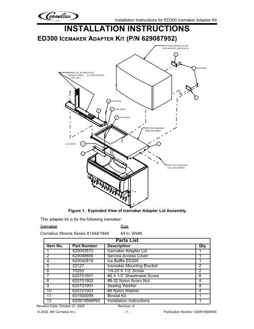
Installation Instructions for ED300 Icemaker Adapter KitINSTALLATION INSTRUCTIONSED300 ICEMAKER ADAPTER KIT (P/N <strong>629087952</strong>)POSITION ICEMAKER FLUSHWITH REAR OF ADAPTER LID57(8-PLACES)MANUAL FILL ACCESS DOORSHOWN AT OPEN & CLOSE POSTIONREF. ONLY6(2-PLACES)528(4-PLACES)9(4-PLACES)POSITION ICEMAKERBASE ON GASKET(4-PLACES)1014USE THE (4) EXISTING8-32 X 3/8 SCREWSThis <strong>adapter</strong> <strong>kit</strong> is for the following <strong>icemaker</strong>:IcemakerSizeCornelius Xtreme Series X1444/1844 44 in. WidthParts ListItem No. Part Number Description Qty.1 620043570 Icemaker Adapter Lid 12 620048806 Service Access Cover 14 620042919 Ice Baffle ED300 15 22127 Icemaker Mounting Bracket 26 70250 1/4-20 X 1/2” Screw 27 620701601 #8 X 1/2” Sheetmetal Screw 88 620701902 #8-32 Nylon Acorn Nut 49 620701901 Sealing Washer 410 620701903 #8 Nylon Washer 411 631500099 Binstat Kit 112 620919566INS Installation Instructions 1Revision Date: October 21, 2002Figure 1. Exploded View of Icemaker Adapter Lid AssemblyRevision: A© 2002, IMI Cornelius Inc. - 1 - Publication Number: 620919566INS
Installation Instructions for ED300 Icemaker Adapter KitCAUTION: Disconnect electrical power to the dispenser before proceeding with theIcemaker Adapter Kit <strong>installation</strong>.WARNING: The dispenser must be secured with 3/8-16 bolts (6) to the counter beforeinstalling this Icemaker Adapter Kit. Refer to the <strong>installation</strong> manual and Fig. 2 for thecounter mounting template.Refer to Fig. 1 for the following procedure:1. Remove the plastic ice storage hopper covers (2) that were shipped with the unit.2. Remove the (2) screws from each side of the dispenser cabinet. Position the <strong>icemaker</strong><strong>adapter</strong> lid on the dispenser and use the (4) cabinet screws to secure the lid to the cabinet.3. Install the ice baffle (item 4) to the <strong>adapter</strong> lid as shown in Fig. 1.4. Remove the <strong>icemaker</strong> front panel and position the <strong>icemaker</strong> on the gasket provided on the<strong>adapter</strong> lid. The <strong>icemaker</strong> should be flush with the rear fo the <strong>adapter</strong> lid. Important: Do notslide the <strong>icemaker</strong> into position on the lid. Lift and set the <strong>icemaker</strong> base onto the<strong>adapter</strong> lid to avoid damaging the gasket seal.5. Using the <strong>icemaker</strong> mounting brackets (item 5) as templates, drill .147 diameter holes (drillsize 26) into the <strong>icemaker</strong> cabinet and the <strong>adapter</strong> lid. Use caution so as not to drill intoany <strong>icemaker</strong> component (condenser, tubing, ETC.). Secure the mounting brackets to the<strong>icemaker</strong> and <strong>adapter</strong> lid with the #10 sheetmetal screws (item 7) provided in the <strong>kit</strong>.6. Follow the <strong>icemaker</strong> manufacturer’s <strong>instructions</strong> provided with the bin thermostat <strong>kit</strong> toinstall the support rod on the <strong>icemaker</strong> base and to route the thermostat capillary tube.Important: The bin thermostat support rod and capillary tube must not interfere withagitator rotation. Complete the <strong>icemaker</strong> <strong>installation</strong> procedure.7. Check that the automatic agitation timer located in the dispenser’s electrical control box isset for automatic fill cube ice. The control box is located behind the merchandiser. Removethe merchandiser by lifting up on the sides to disengage the mounting “hooks” from the cabinetslots and rotating forward. Refer to the label in the control box for setting the agitationtimes.8. Install the service access cover (item 2) on the adaper lid (item 1) with the 1/4-20 screws(item 6) provided in the <strong>kit</strong>. Check for proper operation of the door; it should be free to openby lifting up on the door handle to the left open position.9. The unit is now ready for operation.Publication Number: 620919566INS - 2 - © 2002, IMI Cornelius Inc.
Installation Instructions for ED300 Icemaker Adapter Kitø 7/16(6) PLCS44 3/81 13/1640 3/44 1/220 3/82 9/1616 1/81 5/16OPENING18 5/81221 1/4*1529 3/431 1/2REMOVABLESINK8 1/26 11/163 1/28 5/81522 3/83 3/16TO FRONT OF DRIP TRAYON COUNTERTOPTO FRONT TOP OFDRIP TRAYRECOMMENDED COUNTER OPENING SIZE 12” X 15”FOR UTILITIES AND BEVERAGE TUBING.Figure 2. Mounting Template© 2002, IMI Cornelius Inc. - 3 - Publication Number: 620919566INS