INSTALLATION INSTRUCTIONS - IMI Cornelius
INSTALLATION INSTRUCTIONS - IMI Cornelius
INSTALLATION INSTRUCTIONS - IMI Cornelius

You also want an ePaper? Increase the reach of your titles
YUMPU automatically turns print PDFs into web optimized ePapers that Google loves.
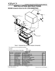
<strong>IMI</strong> CORNELIUS INC One <strong>Cornelius</strong> Place Anoka, MN 55303-6234Telephone (800) 238-3600 Facsimile (612) 422-3246<strong>INSTALLATION</strong> <strong>INSTRUCTIONS</strong>ICE BANK CONTROL KIT (P/N 569000257)FORVANGUARD 245 POST–MIX OVERCOUNTER DISPENSERS(P/N 417306000XXXXX AND 417308000XXXXX)Read and understand these instructions thoroughly before installing this kit. Retain these instructions as part ofyour equipment manual.NOTE: This Ice Bank Control Kit (P/N 569000257) is to be installed on Vanguard 245 Post–Mix Dispensers(P/N 417306000XXXXX and 417308000XXXXX).NOTE: Only qualified personnel should install this Kit.Loose-Shipped PartsItemNo. Part No. Name Qty.1 440000902 Ice Bank Control Module (see NOTE 1) 12 560003999 Mounting Bracket, Ice Bank Control Module (see NOTE 1) 13 440000903 Probe, Ice Bank Control (see NOTE 2) 14 560003811 Probe Bracket, Coil (see NOTE 2) 15 560003595 Probe Holder (see NOTE 2) 16 189955000 Pop Rivet (see NOTE 2) 17 560003812 Jumper Wire “A”, Main 18 560003813 Jumper Wire “B”, Agitator Motor 19 560003814 Jumper Wire “C”, Compressor 110 560003815 Jumper Cable, (Two–Conductor) 111 164884002 Power Relay, 120 VAC, 60 Hz (see NOTE 3) 112 325282000 Screw, Self Drilling, Hx. Hd.; No. 8–18 Thread X 1/2-in. Long 813 569000258 Installation Instructions 114 690945000 Wire Tie 415 560003826 Relay Cover (see NOTE 3) 116 3847 Black Lead Wire, 12–in. Long 1<strong>IMI</strong> <strong>Cornelius</strong> Inc; 1999November 11, 1999569000258
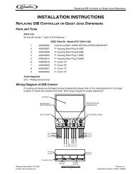
RESTORING UNIT TO OPERATION1. Install drop–in refrigeration assembly back in the Unit.2. Plug in the drop-in refrigeration assembly power cord and electric dispensing valves power cord.3. Fill water tank with water, then install plastic plug in water fill hole.4. Plug Unit power cord into electrical outlet. Test Unit for proper operation.5. Install hood on Unit and secure with screw.GLOBAL ICE BANK CONTROL (GIBC) THEORY OF OPERATIONOnce electrical power is supplied to the Unit, the agitator motor will start. There will be a three-minute time delaybefore the refrigeration compressor and the condenser fan motor will start. This three-minute time delay willtake place each time electrical power to the Unit is interrupted.The Unit will continue to operate until ice covers all three stainless-steel pins on the ice bank control probe. Theice bank control module senses this by measuring the difference in electrical resistance between the water andthe ice. When the ice on the evaporator coil becomes thick enough, it covers the three stainless-steel pins onthe ice bank control probe. The control module senses there is enough ice and turns the refrigeration compressorand the condenser fan motor off.The Unit remains turned off until the the ice bank control three stainless-steel pins are free of ice. Once thishappens, the ice bank control module starts the refrigeration compressor and the condenser fan motor.5690002584
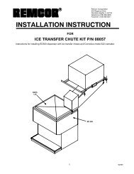
ICE BANK CONTROL MODULEWIRING HARNESSCONNECTOR (BLACK)UNIT FRONTCOIL NO. 2TIE WRAP THEPROBE’S ELECTRICALWIRE HERE5-IN.COIL NO. 3COIL NO. 2CABLE TIE (ITEM 20)(TWO PLACES)COIL NO. 3NOTE: ICE BANK CONTROL PROBE MUSTBE INSTALLED INSIDE OF NO. 2 AND NO. 3EVAPORATOR COILS AS SHOWN.FIGURE 1. PARTS IDENTIFICATION5 569000258
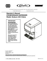
569000258*TWO LEADCONDUCTOR(BLACK)**6BLACK JUMPERWIREBLK OR BRNWHT OR BLU* DISCONNECT ICE BANK CONTROL ELECTRICAL WIRES FROMCOMPRESSOR AND TERMINAL BLOCK TERMINALS, THEN DISCARD OLD ICEBANK CONTROL.*DISCONNECT “RIBBED TO WHITE” JUMPER WIRE CONNECTED BETWEENCOMPRESSOR AND TERMINAL BLOCK, THEN DICARD JUMPER WIRE.*DISCONNECT GRN OR GRN/YEL WIRE CONNECTED BETWEEN GROUNDSTUD AND POWER CORD GROUND TERMINAL. DISCARD GRN OR GRN/YELWIRE.FIGURE 2. WIRING DIAGRAM (OLD ICE BANK CONTROL SHOWN)
178937 56900025817FIGURE 3. WIRING DIAGRAM (NEW ICE BANK CONTROL SHOWN)16CONNECTOR10TWO-LEADCONDUCTOR(BLACK 10)POWER(ITEM 11)