Stratabox⢠Marine Geophysical Instrument
Stratabox⢠Marine Geophysical Instrument
Stratabox⢠Marine Geophysical Instrument

Create successful ePaper yourself
Turn your PDF publications into a flip-book with our unique Google optimized e-Paper software.
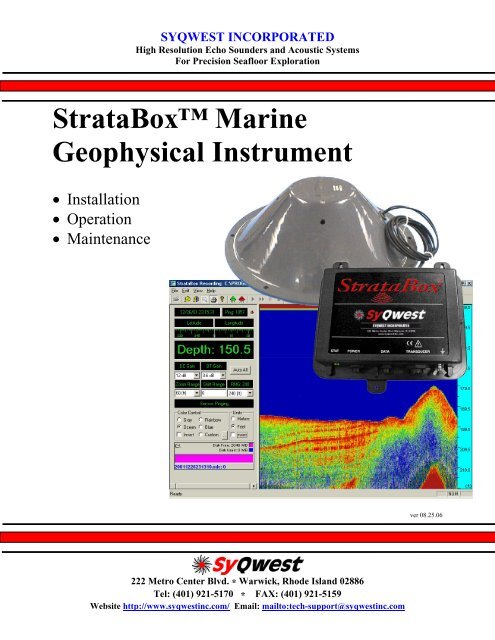
SYQWEST INCORPORATEDHigh Resolution Echo Sounders and Acoustic SystemsFor Precision Seafloor ExplorationStrataBox <strong>Marine</strong><strong>Geophysical</strong> <strong>Instrument</strong>• Installation• Operation• Maintenancever 08.25.06222 Metro Center Blvd. * Warwick, Rhode Island 02886Tel: (401) 921-5170 * FAX: (401) 921-5159Website http://www.syqwestinc.com/ Email: mailto:tech-support@syqwestinc.com
TABLE OF CONTENTS1.0 INTRODUCTION..............................................................................................................................1-11.1 GENERAL INFORMATION............................................................................................................1-11.2 ABOUT THIS MANUAL ...............................................................................................................1-11.3 ECHO SOUNDING PRINCIPLES ....................................................................................................1-21.3.1 Underwater Acoustics........................................................................................................1-21.3.1.1 Decibels..........................................................................................................................1-21.3.1.2 Sound Propagation .........................................................................................................1-21.4 SPECIFICATIONS .........................................................................................................................1-71.4.1 StrataBox Sensor Specifications ........................................................................................1-72.0 INSTALLATION...............................................................................................................................2-12.1 - STRATABOX SYSTEM INSTALLATION OVERVIEW ...................................................................2-12.1.1 - Getting Started................................................................................................................2-22.1.2 - Installing the StrataBox Electronics................................................................................2-32.1.3 - Installing the StrataBox Transducer................................................................................2-52.1.4 - Electrical Connections...................................................................................................2-112.2 - STRATABOX PC SOFTWARE INSTALLATION .........................................................................2-143.0 OPERATION .....................................................................................................................................3-13.1 STRATABOX PC SOFTWARE ......................................................................................................3-13.1.1 - The Main Window............................................................................................................3-13.1.2 – The Menu Bar .................................................................................................................3-53.1.2.1 – The File Menu.............................................................................................................3-53.1.2.2 – The Edit Menu ..........................................................................................................3-113.1.2.3 – The View Menu ........................................................................................................3-113.1.2.4 – The Help Menu .........................................................................................................3-134.0 MAINTENANCE...............................................................................................................................4-14.1 – POST (POWER ON SELF TEST) ...............................................................................................4-14.2 – LED INDICATOR......................................................................................................................4-14.3 – FIRMWARE UPDATE ................................................................................................................4-14.3.1 – Connection ......................................................................................................................4-24.3.2 – Firmware Update File ....................................................................................................4-24.3.3 – StrataBox PC Software Firmware Update......................................................................4-24.4 – TROUBLESHOOTING ................................................................................................................4-34.4.1 – StrataBox Sensor Troubleshooting .................................................................................4-34.4.2 – StrataBox PC Software Troubleshooting........................................................................4-3TABLE OF CONTENTS I
TABLE OF FIGURESFigure 1-1 Absorption Coefficient Versus Frequency ..........................................................................1-3Figure 1-2 Acoustic Beam Pattern.........................................................................................................1-6Figure 2-1 System Interconnect Diagram..............................................................................................2-2Figure 2-2 Bulkhead Mounting the Sensor Unit ...................................................................................2-5Figure 2-3 Transducer Mounting Ring..................................................................................................2-7Figure 2-4 Over The Side Transducer Mounting..................................................................................2-8Figure 2-5 StrataBox Sensor Unit Connections...................................................................................2-11Figure 2-6 StrataBox Sensor Power Connector ..................................................................................2-12Figure 2-7 StrataBox Sensor Data Connector.....................................................................................2-13Figure 2-8 StrataBox Sensor Transducer Connector .........................................................................2-13Figure 2-9 Printer Port.........................................................................................................................2-14TABLE OF TABLESTable 2-1 Basic Equipment .....................................................................................................................2-2Table 2-2 Accessories and Options.........................................................................................................2-3Table 2-3 Portable Transducer Installation Parts ................................................................................2-7Table 2-4 StrataBox System Cables .....................................................................................................2-11TABLE OF CONTENTS II
STRATABOX Operations and Maintenance Manual1.0 INTRODUCTION1.1 General InformationThe StrataBox is a portable, low power, high-resolution, and water-resistant marine sediment imaginginstrument capable of delivering 6 cm of marine sediment strata resolution with bottom penetration of upto 40 meters. It is designed exclusively for inshore and coastal geophysical marine survey up to 150meters of water depth and operates at 10 kHz. Included with the StrataBox product is the following:• StrataBox Sensor Unit• StrataBox Transducer Assembly• StrataBox Installation CD• StrataBox ManualStrataBox Sensor Unit provides all of the transmit/receive electronics, and all of the signal processingfunctions. It is powered from a 10-30VDC source and consumes 8 watts of power. It interfaces to theHost PC via a single COM port. The mechanical case for the Electronics Unit is Water Resistant to theEN60529 IP65 Specification and is also UV Stable and Chemical Resistant.The StrataBox Transducer Assembly is a Line-in-Cone type transducer with an anodized aluminumring attached. The ring provides a means to affix the transducer to the appropriate mounting hardware.The transducer itself provides 300 Watts of Low Frequency energy for bottom penetration of up to 40meters (sediment dependent). It is lightweight and well suited for portable applications.The StrataBox Installation CD will install the PC software used to configure, control, and acquire datafrom the StrataBox Sensor device. It will also include this manual in PDF format and any Release Notesthat have been generated.A hardcopy of the StrataBox Manual is also included so that the user may learn to install, operate, andmaintain the StrataBox Equipment and Accessories. The manual also includes a section on acoustictheory.The StrataBox PC software was designed for use with the Windows 98 operating system, but shouldoperate under Windows 95/ME/NT/2000/XP also. We recommend the software be used on a PC with aprocessor speed of at least 266 MHz. The software requires at least 1 available Serial Port for connectionto the StrataBox instrument, and optionally, additional Serial Ports for NMEA Navigation/GPS Input,NMEA Depth Out, and External Annotation. The software features Navigation Input, ExternalAnnotation, Data Storage, Zoom Modes, Thermal Printer output, Automatic/Manual Eventing, and more.The StrataBox software interface is divided into two fields. The Controls field is located on the left andcontains navigation/depth information, configuration buttons, and system status. The Data field islocated on the right and contains the actual acoustic echo data.1.2 About This ManualThis manual contains important information regarding acoustic theory, installation, operation andmaintenance of your new equipment. The user should take sufficient time to read the entire manual andto understand the full functionality of the StrataBox Sensor and PC Software.The manual is organized into four chapters:1) An introduction (this section), which provides a system overview and basic outline of echosoundingacoustics.INTRODUCTION 1-1©2006 SyQwest Incorporated
Operations And Maintenance ManualSTRATABOX 2) Installation, which provides details on how to properly mount all of the StrataBox Systemcomponents. Details on installing the StrataBox PC Software package are included also.3) Operational instructions describing how to operate the StrataBox Sensor unit and the StrataBox PCSoftware.4) Maintenance, which provides information on replaceable parts and troubleshooting guidelines.The user should pay attention to notes that are displayed in a gray box. These notes contain importantinformation regarding installation and use of the StrataBox System. An example is given below:NOTE: Important operation and installation information is provided in gray boxesthroughout the manual.1.3 Echo Sounding PrinciplesBasic echo sounding principles that should be understood by all operators of hydrographic equipment areprovided in this section.1.3.1 Underwater Acoustics1.3.1.1 DecibelsThe scale most often used to describe a measurement unit of sound is the decibel (abbreviated “dB”). Thedecibel system was selected for a number of reasons. First, it is a logarithmic system, which is useful fordealing with large changes in measured quantities. Decibel units make multiplication and division simplebecause they are reduced to an addition and a subtraction operation respectively. Secondly, forunderwater acoustics, the primary concern is ratios of power levels and signal levels rather than absolutenumeric values.Transducer calibration values are typically provided in units of decibels, including source level, receivesensitivity and directivity index. These transducer calibration values are outlined later in this section.These quantities are used to predict performance levels of a given transducer used with a sonar system.1.3.1.2 Sound PropagationThe sea, together with its boundaries, forms a remarkably complex medium for the propagation of sound.Figure 1-2 shows the interaction of a transmitted sound source and the water. Both signal loss andinterference result from interactions with boundaries and components within the water column, causingthe source to be delayed, distorted and weakened. The main components affecting sound propagation arespreading loss and attenuation loss.Spreading LossAs a transmitted pulse of sound leaves the transducer, it spreads out in all directions. At the transmissionpoint, the sonar puts a fixed amount of energy into the water. As the pulse travels away from thetransducer, it occupies a greater and greater volume. This effect is called spherical spreading. Thegeneral rule is that the intensity of the sound falls off as the square of the distance traveled. In respect totypical acoustic measurements, this mathematically becomes a loss of 6 decibels for each doubling of thedistance.INTRODUCTION 1-2©2006 SyQwest Incorporated
STRATABOX Operations and Maintenance ManualFor echo sounders, the distance actually traveled is two times the distance to the seafloor from the sourcetransducer (from the transmission source, to the bottom and back again). This results in a significantsource of signal loss for the system receiving the sound pulse, which must be compensated for at thereceiver. Typically a Time Varied Gain (TVG) amplifier is used to correct for spherical spreading loss inan acoustic receiver. A TVG amplifier works by applying an increasing amount of gain to the returnsignal as time of travel increases.Attenuation LossAttenuation of sound energy in the oceans comes from three factors: absorption, scattering (orreverberation) and bottom loss. Sound absorption takes place at two levels; one, absorption in the actualseawater medium, and two, absorption into the seafloor. Primary causes of absorption are viscosity andthermal conductivity in the molecules of water as the sound travels. At the molecular level, absorption isprimarily related to frequency. At high frequencies- 500 kHz, for example, a loss of 0.14 dB/meteroccurs in seawater, while at 50 kHz the loss is only 0.014 dB/meter. This is a major concern whenselecting a transducer required to meet specified depth criteria. A graph showing the attenuation lossversus frequency is shown in Figure 1-1.Figure 1-1 Absorption Coefficient Versus Frequency©2006 SyQwest IncorporatedINTRODUCTION 1-3
STRATABOX Operations and Maintenance ManualCavitation is a result of the pressure on the face of the transducer reducing to a level that permits thewater to boil (i.e. turn from a liquid to a gas). This is directly related to the flow around the transducer asdescribed above. Cavitation is also related to the depth, source level, and frequency of the transducerbeing used. As the depth of the transducer increases, static pressure increases to levels that will preventcavitation from occurring. If the transducer is mounted properly, with flow noise and cavitation levelsconsidered, this phenomenon should never affect an echo sounder.Cavitation may also occur on a ship’s propeller. As the speed of the water increases over the surface ofthe propeller, turbulence causes changes in the static pressure of the water. At this point, if the pressure islow enough, boiling will occur. This process releases a large quantity of bubbles into the water, causingnoise that can affect the performance of an echo sounder. Care should be taken to mount a transducer asfar as possible from this noise source.Ambient NoiseAmbient noise is always present in the ocean. This noise is caused by both natural or human-madeevents. For echosounding principles, ambient noise sources that are significant include hydrodynamicboundaries, ocean traffic and biological transmitters.Hydrodynamic noise results from natural phenomenon such as wind, waves, rain or currents. The levelsproduced vary greatly, but are largely related to the sea state level. In severe storms, hydrodynamic noisecan reach levels that make reception of a transmitted signal very difficult, if not impossible.Ocean traffic noise is dependent on the number of ships, the distance from noise sources, and the currentpropagation conditions due to thermoclines and sea state. Ocean traffic generally produces acoustic noisethat is not within the frequency bandwidth of most navigational echo sounders, except when ships passvery near to the receiving transducer.Biological noise producers include marine life such as shrimp, fish, and mammals. Mechanicalmovements of crustaceans, with their hard shells, may produce significant noise when in large schools.Likewise, certain fish species produce noise by reflecting noise off their swim bladder.Transducer PropertiesProperties of a chosen transducer affect sonar performance which directly relates to depth measurements.The source level, directivity index, and beam width of a transducer have a relationship with how the sonarsystem performs under different conditions.Source LevelSound is created by a transducer from a mechanical vibration of the ceramic material of which underwatertransducers are made. The movement of the transducer face creates alternating regions of high and lowpressure, resulting in an acoustic wave. The amount of energy transmitted into the water column isdefined as the acoustic source level. A source level is expressed in units of decibels that describe theintensity of sound relative to a reference intensity at one unit distance from the sound source. For theuser, a source level is useful for selecting a transducer for a particular use.The amount of movement on the face of the transducer is linearly related to the voltage difference createdacross the ceramics of the transducer. Normally it would seem desirable to put as much power into thewater as possible to achieve maximum depth performance. Cavitation, however, which results from highsource levels and small transducer depths below the sea surface, is generally the limiting factor whendriving a transducer. The electrical and mechanical design of the transducer, which has a maximumrecommended input power level, must also be considered.©2006 SyQwest IncorporatedINTRODUCTION 1-5
Operations And Maintenance ManualSTRATABOX Beam WidthThe beam width of a transducer is described as the width of the main lobe of a transmit pattern. Thewidth is usually measured between the -3 dB points on either side of the beam pattern. Shown in Figure1-2 is a transmit beam pattern for a 125 kHz transducer. The shape of the transducer beam pattern is aresult of the transducer design. An array of ceramic elements, or a single ceramic element, emits sound atgiven frequency. The spacing of the elements and the frequency being used can control the shape of thebeam pattern. At the center of the beam pattern is the main lobe of the transducer, with a width of 7degrees (centered at zero degrees). The -3 dB point is shown as a dashed line on the graph. The sidelobes of this transducer are the smaller lobes, approximately 18 dB below the level of the main lobe.Figure 1-2 Acoustic Beam PatternThe width of a beam is important for calculating how small an object the system can detect. If twoobjects fall within the main beam the object will appear as one object when it is received by the system.Thus, a narrow beam width is required for navigational echo sounders so it is capable of discriminatingsmall objects.The size of the transducer sidelobes (smaller beams off to the side of the main lobe) is important indetermining how the system will behave on steep slopes. On steep slopes, transmitted acoustic energyfrom the side lobes will be received first and reveal a signal that looks like the actual bottom. In reality,the bottom is directly below the ship, and as seen by the main lobe, is much deeper. For this reason, it isimportant to select a transducer which has reduced sidelobes.INTRODUCTION 1-6©2006 SyQwest Incorporated
STRATABOX Operations and Maintenance ManualDirectivity IndexThe directivity index measures the ability of a transducer to reject noise from extraneous sources. In theocean, noise may be coming from all directions, but a narrow beam transducer will only “hear” noisewithin the beam width pattern. A sonar systems signal to noise ratio (SNR) will be affected by the abilityof a transducer to reject unwanted noise, and thus is related to the directivity index. The higher thedirectivity index of a transducer, the better the ability to reject unwanted noise.1.4 Specifications1.4.1 StrataBox Sensor SpecificationsUnits Feet or MetersDepth Ranges0-15, 0-30, 0-60, 0-120, 0-240, 0-450 Feet0-5, 0-10, 0-20, 0-40, 0-80, 0-150 MetersShift Range0-450 Feet in 1 Foot increments0-150 Meters in 1 Meter incrementsZoom Range15, 30, 60, 120, 240 Feet5, 10, 20, 40, 80 MetersZoom Modes Bottom Zoom, Bottom Lock Zoom, Marker Zoom, GUI Zoom (Playback Only)DisplayNormal Data, Zoom Data, Navigation, Depth, Command/Status, Color Controlfor Data: 4 Selections or Custom (User Input), Data Color Invert possibleStrata Resolution 6 cm with 40 Meters of bottom penetrationDepth Resolution 0.1 Feet, 0.1 MetersDepth Accuracy ± 0.5%Speed of Sound 1500 Meters/Second, 4800 Feet/SecondGeographic PositionNMEA 0183, GLL, GGA, RMC, VTG, VHW, HDTSelectable Baud Rates (RS-232): 4800, 9600, 19200, 38400Data Interface SYQWEST StrataBox Interface, 57600 Baud (RS-422)Printer Output Centronics (Parallel Port) interface to TDU Series Thermal PrintersShallow WaterOperation< 2.5 Meters; bottom type dependantTransmit Rate Up to 10 Hz, depth and operator mode dependantEvent Marks Periodic, External, and/or Manual (Periodic selectable in 1 minute intervals)Data File OutputStores Depth, Navigation, and Graphic Data in ODC format (Proprietary)Normal and Zoom Data stored is Pixel data and can be played back and/or printedData File PlaybackFiles can be played back and/or printed at Normal or Fast-Forward speed, withPause and GUI Zoom availableFrequency Output 10 KHzTransmit OutputPower300 Watts (Pulsed), 1000 Watts capableInput Power 10-30 Volts DC, Nominal power 8 Watts, Reverse Polarity and Over VoltageProtectedDimensions 25.4 cm (10”) Length, 15.876 cm (6.25”) Width, and 6.25 cm (2.5”) HeightWeight 0.9 kg (2.0 lbs)-25°C to +60°C Operating Temperature (-55°C to +90°C Storage)Environmental Water Resistant to EN60529 IP65EMC meets EN60945 Emissions; CE Compliant©2006 SyQwest IncorporatedINTRODUCTION 1-7
Operations And Maintenance ManualSTRATABOX THIS PAGE INTENTIONALLY LEFT BLANKINTRODUCTION 1-8©2006 SyQwest Incorporated
STRATABOX Operations and Maintenance Manual2.0 INSTALLATION2.1 - StrataBox System Installation OverviewThis section presents instructions for initial setup and installation of the StrataBox Sensor. Physical andelectrical installation details are provided for connecting, mounting, and getting started with theStrataBox. A summary is given of the software installation and setup procedure as well.Although the StrataBox Sensor is designed to deliver the highest levels of quality and performance, it canbest attain those standards when the equipment has been properly installed. Because of the great varietyof vessels that will employ the StrataBox Sensor, it is not feasible to provide complete and detailedinstructions that will fit all installation possibilities. Therefore, this section will provide practicalguidelines to assist the user in planning a typical installation of the StrataBox System aboard the vessel.Shown in Figure 2-1 is a system-interconnecting diagram. Optional items are shown with dashed lines. Aminimum operational system configuration requires:1. PC running Windows 98 (Windows 95/ME/NT/2000/XP should work as well, Pentium II @266MHz or greater)2. StrataBox Sensor Unit3. StrataBox Transducer Assembly4. StrataBox Cables (Power, Data, Transducer)5. 10-30 Volt DC Power Source (8 Watts)6. Transducer Mounting HardwareThe GPS, NMEA Depth Out, and External Eventing connections are optional but, if used, will require thePC to have additional COM ports. For many portable PC’s additional COM ports may be installed viaone of the PCMCIA expansion slots.The TDU Printer, if used, is attached via the PC’s Printer Port.©2006 SyQwest IncorporatedINSTALLATION 2-1
Operations And Maintenance ManualSTRATABOX Figure 2-1 System Interconnect Diagram2.1.1 - Getting StartedUnpacking and InspectionUse care when unpacking the unit from it’s shipping carton to prevent damage to the contents. It is alsorecommended that the carton and the interior packing material be saved even after the unit has beeninstalled on the vessel. In the unlikely event that it is necessary to return the unit to the factory, theoriginal carton and packing material should be used. Verify that all parts described in the next sectionhave been shipped with the unit.Basic EquipmentThe following (Table 2-1) is a list of the basic equipment supplied with the StrataBox <strong>Geophysical</strong><strong>Instrument</strong> (P04400):PartNumberItemQuantityP04403 StrataBox Sensor Unit 1P04462 StrataBox Transducer Assembly 1P04412 Power Cable (10 feet) 1P04413 Data Cable (10 feet) 1P04415 Transducer Cable (30 feet) 1P04421 StrataBox Software CD 1P04425 StrataBox Manual 1Table 2-1 Basic EquipmentINSTALLATION 2-2©2006 SyQwest Incorporated
STRATABOX Operations and Maintenance ManualAccessories and OptionsThe following items are available to complement and enhance the operation of the StrataBox Profiler.Please contact your authorized SYQWEST distributor or visit our web site for information and assistancein obtaining any of these items.ProductCodeItemQuantityP02553 TDU-850 Thermal Printer 1P03100 TDU-1200 Thermal Printer 1P03120 TDU-2000F Thermal Printer 1P03050 12 Channel DGPS System w/ Combo Antenna 1P04465 Over-the-Side Mounting Kit 1Table 2-2 Accessories and Options2.1.2 - Installing the StrataBox ElectronicsInstructions are provided in this section regarding the physical installation of the StrataBox Sensor Unitand the PC that is used for the User Interface. Guidelines are provided for locating and/or mounting theStrataBox Sensor unit and the PC. The installer should refer to Section 2.1.4 for information on electricalhookup.Selecting a Location for the ElectronicsThe StrataBox Sensor Unit is designed for portable, marine applications but maybe used in permanentinstallations as well. The user must determine if the StrataBox Sensor Unit is to be mounted on the vesselor just placed in a convenient place on-board the vessel. Either way the appropriate location for the unitneeds to be determined. The following considerations should be investigated before deciding upon alocation:1. User Supplied Personal ComputerThe first step in the equipment location process is to determine the optimum place for viewing the data.The unit should be positioned to provide the optimum viewing angle and within easy reach of the operatorwhenever possible. This will vary depending on the size of the vessel and type of Personal Computer(Desktop or Laptop) but is most important to insure the comfort and success of the user. The locationselection should consider that standard PC displays are not easily readable in direct sunlight. Adequatespace for the computer and any peripherals that need to be connected should be considered as well.Finally, provisions need to be made to properly secure the equipment for the worst sea conditions thatmay be encountered.2. Cable Lengths.Both the Data Interface Cable and the DC Power Cable supplied with the product are 10 feet long. Thus,the Sensor Unit must be installed within 10 feet of both the user supplied Personal Computer and a 10-30VDC Power Source. The unit must also provide adequate access for cabling termination withoutbinding, and allow suitable space for servicing the equipment. (If necessary, the data cable may beextended beyond 10 feet. See Section 2.1.4 for more information)©2006 SyQwest IncorporatedINSTALLATION 2-3
Operations And Maintenance ManualSTRATABOX 3. Water Resistance.The Sensor Unit has passed the EN60529 IP65 Water Resistance Standard which insures that the unit iscompletely sealed and is Splash Proof. The unit should NOT however be installed in an area where theunit may be submerged in water.4. Environmental.The operating temperature of the StrataBox Sensor is –25C to +60C thus the operating temperature rangeof the PC is likely the limiting factor for temperature. The unit has also passed all of the EN60945emission tests (radiation and immunity). For optimum system performance it is still recommended thatthe installer mount or place the Sensor unit in an area that is at least several feet away from any otherelectronic equipment or machinery on the vessel. The unit should also be mounted or placed in an areathat won’t be exposed to water if practical.Mounting the Sensor UnitThis section outlines the steps for mounting the Sensor Unit. Refer to Figure 2-2 while installing. Theunit may be mounted either horizontally or vertically. The keyhole slots make installation in hard toreach areas easier, but be sure to tighten all mounting hardware securely. Insure that adequate room is leftfor installing and removing the cable connections. Also, verify that the status indicator (labeled STAT) isvisible.Step 1) Confirm that the area behind the intended-mounting surface on the bulkhead is clear ofequipment, panels, electrical cables, conduits, hydraulic, air, water lines or pipes.Step 2) Using the Sensor Unit as a template mark a drill point for each of the mounting holes. Insure thatthe marks for the keyholes are placed in the smaller, slotted areas.Step 3) Drill four (4) holes that will work with the mounting hardware that has been selected (notsupplied). The 4 holes on the Electronic unit are .195 inches in size (#8 size Screw recommendedfor installation).INSTALLATION 2-4©2006 SyQwest Incorporated
STRATABOX Operations and Maintenance ManualFigure 2-2 Bulkhead Mounting the Sensor Unit2.1.3 - Installing the StrataBox TransducerGeneral TransducerThe StrataBox is equipped with a single lightweight, Line-in-Cone transducer that is designed forportable, over-the-side mount applications. It may also be used in permanent installations but will need tobe mounted in a water filled seachest in those installations. Before installing the transducer, the installershould read and understand the appropriate section below to insure that all of the installation issues areconsidered.Selecting a Location for the TransducerThe location of the transducer is very important for maintaining reliable bottom tracking and optimumsubbottom performance of the equipment. Avoid installing transducers in locations where the transducerwill be subjected to turbulent water, air bubbles, or vibration. The best clear water location on mostvessels meeting these criteria is approximately 1/3 the length of the vessel, aft from the bow.For many portable applications and some permanent applications it is not practical to mount thetransducer in the forward section of the vessel. For these applications the transducer can be located in theaft third of the vessel; away from and forward of shafts and propellers, clear of hull openings, sea chests,outlets or protuberances. It is preferable to mount the transducer on the side of the hull where thepropeller blades are normally moving downwards. The upward motion of the propeller can generatepressure waves, which push air bubbles up against the hull. By mounting the transducer on the downwardside, the hull will tend to protect the transducer from this effect.©2006 SyQwest IncorporatedINSTALLATION 2-5
Operations And Maintenance ManualSTRATABOX The transducer should be mounted adjacent to the ship’s centerline. The radiating face should be flushwith the hull and, wherever practical, the face should be parallel to the waterline. A maximum deadriseangle of 3 degrees is allowable.The transducer must be mounted such that it will always remain submerged during operation. Thus, thedepth of the transducer should take into account the location on the vessel and the worst case sea stateconditions. Turbulent flow across the radiating face of the transducer and/or the presence of air bubbleswill degrade system performance significantly as well and must be considered.The area selected for mounting must provide sufficient space for access to the transducer and cable, andfor routing cable and conduit. In addition, there should be sufficient room to permit use of the necessarytools to facilitate the installation-mounting requirements. Ideally, the location would provide a relativelydirect cable run to the site of the StrataBox Sensor Unit.The cable path from the Electronics to the transducer should be routed as far as possible from otherelectrical cables. Although the cable is shielded, the acoustic reply from the transducer can be on theorder of microvolts, thus any cable crosstalk emissions can cause a decrease in acoustic sensitivity.Handling TransducersThe transducer is the heart of the StrataBox system and, in spite of its appearance and size, is a delicateinstrument. Although it is designed to be in contact with and survive tough marine environments, itshould not be dropped or mishandled during the installation. Caution is advised when handling thetransducer to prevent any damage to the transducer face or radiating surface.The Line-in-Cone transducer is comprised of a large ceramic, cylindrical ring element affixed to a plasticcone with baffling. The Transducer Mounting Ring is provided to make it easy to secure the StrataBoxTransducer to a mounting surface. This assembly also provides protection for the Transducer and shouldbe affixed to the transducer at all times. The transducer and mounting assembly should be as clean andsmooth as possible so the path of the sounding energy is uninterrupted. The transducer face must not bepainted with lead based bottom paint. In portable applications the transducer and mounting assemblyshould be cleaned with fresh water after use.WARNING: Do not expose the transducer to any solvents when cleaning any excesssealants. Strong solvents may damage the face of the transducer.INSTALLATION 2-6©2006 SyQwest Incorporated
STRATABOX Operations and Maintenance ManualØ16.38 (416mm) Dia.Ø0.50 (12.7mm) Dia. (2 PLcs.)MOUNTING RINGSPIDER MOUNT(REFERENCE)PIPE FLANGE 1" DIA PIPEMOUNTING HOLESØ0.404 (10.26mm) THRU, 6 PLACESEQ. SPACED ON A Ø15.13(384.3mm)B.C.Ø5.5" (139.7mm) Dia.5.75"(146mm)ASSEMBLYFigure 2-3 Transducer Mounting RingAlso, when handling the transducer, avoid lifting or pulling on the transducer cable. Although the cableappears thick and substantial, the internal cable wiring could be damaged by stress from the sheer weightof the transducer and cause a malfunction at the most inopportune time.Portable Transducer InstallationPortable installations of the StrataBox transducer for most survey vessels will be of the over-the-side pipemount type. This type of installation is achieved with the following list of materials:Part Number Item QuantityP02590 StrataBox Transducer 1P04462 StrataBox Transducer Mounting Assembly 1User Supplied Silicone grease or petroleum jelly (Vaseline®) 1User Supplied Pipe coupling 1User SuppliedPipe with threads to match the pipe coupling and length to giveproper transducer depth1User Supplied Pipe coupling adapter 1User Supplied Support Lines or cables 2User Supplied Pipe Clamps to affix the Pipe to the 4x4 1 (or 2)User Supplied Pressure Treated 4x4x (Ship’s Beam Width + 2 feet) 1User Supplied Large “C” Clamps to affix the 4x4 across the beam of the vessel 2User Supplied Protective Pads or Carpet Remnants 2User Supplied Mild Household Detergent (i.e.,dishwashing liquid) 1Table 2-3 Portable Transducer Installation Parts©2006 SyQwest IncorporatedINSTALLATION 2-7
Operations And Maintenance ManualSTRATABOX Refer to Figure 2-4 below while reading and implementing the Installation procedure listed below.Figure 2-4 Over The Side Transducer MountingINSTALLATION 2-8©2006 SyQwest Incorporated
STRATABOX Operations and Maintenance ManualCAUTION: Never pull, carry or hold the transducer by the cable as this may severinternal connections.Installation Procedure:1. Apply silicone grease or petroleum jelly to the threads of the pipe to facilitate later disassembly.2. Twist the pipe coupling onto the pipe.3. Push the transducer cable through the pipe. Alternately after the transducer is attached, clamp thecable to the outside of the pipe using cable clamps.4. Apply silicone grease or petroleum jelly to the transducer stem. Insure that the grease does not smearthe face of the transducer.5. Attach 2 lines or cables to the Transducer Mounting Assembly. These lines or cables will support thepipe from the force of the water when the boat is underway.6. Attach the Pipe Clamp(s) near the end of the 4x4 insuring that there is enough clearance for thetransducer to hang over the side of the vessel.7. Place the 4x4 across the beam of the vessel near the stern and fasten it to the gunnels with the CClamps. Use the Protective Pads or Carpet Remnants to protect the gunnels of the vessel. Insure thatthe 2 foot extra length of the 4x4 extends beyond the beam of the vessel on the appropriate side andthat the Pipe Clamp(s) attached to the 4x4 are on the extra length as well.8. Attach the Transducer/Pipe Assembly to the 4x4 using the Pipe Clamps. Insure that the transducer isdeep enough into the water that sea conditions will not cause the transducer to get to the surface.9. Fasten the line(s) or cable(s) fore and aft with sufficient tension to support the pipe when the boat isunderway.10. Route the cable to the instrument being careful not to tear the cable jacket. To reduce electricalinterference, separate the transducer cable from other electrical wiring. Coil any excess cable andsecure it in a place with zip-ties to prevent damage.Portable Transducer MaintenanceAquatic growth can accumulate rapidly on the transducer's surface reducing its performance in weeks.Clean the surface, keeping it free of marine growth and petroleum residue, with a soft cloth and mildhousehold detergent. Inspect the cable periodically for kinks, abrasions and cuts. Repair any damageusing an approved waterproofing cable repair system. Inspect connections for indications of corrosion.WARNING: NEVER USE SOLVENTS!Certain cleaners, gasoline, paint, sealants and other products may contain strongsolvents, such as acetone, which can attack many plastics dramatically reducingtheir strength. Clean surface of transducer with a mild detergent only.Permanent Transducer InstallationFor some applications it may be necessary and/or convenient to mount the StrataBox Transducerpermanently in the hull of the vessel. Due to the construction of the StrataBox Transducer it may NOT bedirectly affixed to the hull of the vessel. A Seachest Installation is required. Guidelines for performing aSeachest installation are described in the following sections.©2006 SyQwest IncorporatedINSTALLATION 2-9
Operations And Maintenance ManualSTRATABOX Seachest Transducer InstallationInterior Seachest installations are best suited for solid fiberglass hulls to permit a minimum attenuation ofacoustic reply signals. Hulls of other type material types may be considered but most other hull types willrequire that a Seachest design be built into the hull with an acoustic window across the face of theenclosure (i.e. a significant hole must be cut out of the hull).Inside mounting to the hull does minimize drag to allow faster survey speeds, however, significant loss ofsubbottom performance may result due to the attenuation loss in the hull.Locate the transducer where the hull is solid fiberglass resin to maximize sound transmission. Do notlocate over balsa wood core material. Consult the hull manufacturer if you are unsure of the core materialor the best location. Never bond large resin housings directly to the hull; always use a liquid-filled box.In any permanent installation the intended final configuration should be tested before it is implemented, ifpossible.For more information regarding the installation of a Seachest or other permanent transducer mount, referto our website at http://www.syqwestinc.com/support/install/xducer.htm, or contact us directly.INSTALLATION 2-10©2006 SyQwest Incorporated
STRATABOX Operations and Maintenance Manual2.1.4 - Electrical ConnectionsWARNING: Be sure to turn the vessel power off at the main switchboard beforeproceeding with the installation. If power is left on or turned on during theinstallation, then fire, electrical shock or other serious injury may occur.There are 3 connections that need to be made to the StrataBox Sensor Unit and the PC for the systemfunction properly. The user also has the option of connecting a GPS input and/or a Thermal Printer. Thesections below describe the connection details for each.All electrical connections to the StrataBox Sensor unit are to the side of the unit. Refer to the sections oneach individual connector for information on connector type, recommended cable and wiring specifics.Figure 2-1 at the beginning of the chapter shows the overall systems interconnect for the system.Figure 2-5 StrataBox Sensor Unit ConnectionsFigure 2-5 shows the basic connections to the unit. In all installations, all of the connections must bemade for the unit to function. As shown above, there is a status indicator (STAT) and there are 3connectors from left to right: DC Power (3 pins), Data Interface (8 Pins), and the Transducer (10 Pins). Agrounding screw, located to the right of the Transducer connector, is provided to connect the StrataBox tothe vessel’s earth ground system. The cables supplied with the StrataBox are ready to plug into theStrataBox Sensor Unit. No user wiring is necessary. The cables associated with the StrataBox SensorUnit are listed below (Table 2-4). The user should make sure that, after wiring is complete, each plug isfirmly attached to the unit via the twist-lock mechanism.Part Number Item QuantityP04412 DC Power Cable (10 feet) 1P04413 Data Interface Cable (10 feet) 1P04415 Transducer Cable (30 feet) 1Table 2-4 StrataBox System Cables©2006 SyQwest IncorporatedINSTALLATION 2-11
Operations And Maintenance ManualSTRATABOX DC Power ConnectionBefore installing the power connection to the unit, the installer must first insure that the DC power sourceis in the range of 10-30VDC and is capable of providing 8 watts of power to the unit. Although theStrataBox Sensor unit is reverse polarity and over-voltage protected, it is always required that the powermains be turned off during system wiring for both personal and equipment safety.The Power Cable supplied with the system is 10 feet long, and includes 3 conductors. The wires in thepower cable must be connected as follows:REDBLACKWHITE– Positive DC Voltage (Fused Lead), DC IN+– DC Return, DC IN-– Earth Ground, SHLDThe Positive DC Voltage lead includes a 3 Amp in-line Fuse. In the unlikely event that the fuse is blownit should be replaced with a fuse of the same amperage. Installing an incorrect fuse can result in damageor fire to the unit if it is not operating properly.The Power Connector on the Sensor Unit is shown below in Figure 2-6.Figure 2-6 StrataBox Sensor Power ConnectorElectrical wiring standards require that the StrataBox Sensor Unit be properly attached to a solid chassisground via the ground stud on the bottom of the unit, or the Earth Ground wire (WHITE) in the powercable. When connecting to the ground stud, a tinned copper braided wire (0.190 gauge or greater) isrecommended.NOTE: Connecting the Earth Ground is required for optimum system performance andsafe operation. The white wire in the power cable OR (BUT NOT BOTH) a groundwire to the unit ground stud is needed. Connecting both the white wire and theground stud to earth ground may degrade performance due to induced groundloops.INSTALLATION 2-12©2006 SyQwest Incorporated
STRATABOX Operations and Maintenance ManualData Interface ConnectionThe Data Interface cable supplied with the StrataBox is 10 feet long. It includes 8 conductors and an RS-422 to RS-232 conversion block. This block connects directly to the COM port of the PC and derives itsinput power from the DTR and/or RTS signal lines from the PC. For nearly all applications, the DataInterface can be connected as supplied.If the 10 foot length of cable is not enough, the Data Interface Cable may be extended by using astandard, 1 to 1, 9 pin D to 9 pin D extension cable. This cable must be connected between the RS-422side of the conversion block and the 9 pin D connector attached to the Data Interface cable. Theextension cable must be shielded to guard against interference. The Data Interface Connector on theSensor Unit is shown below in Figure 2-7Transducer ConnectionFigure 2-7 StrataBox Sensor Data ConnectorThe StrataBox transducer wiring is comprised of 2 cable sections.The first cable section is 6 feet long and is directly connected to the ceramic inside the transducer. Thereis a waterproof inline connector at the end of this cable section suitable for connection in a floodedseachest or in seawater.The second cable section is 30 feet in length and has the waterproof mate to the first cable section on oneend and a 10 pin connector on the other end that mates to the Transducer connector on the StrataBoxSensor Unit. Only 3 of the pins on the 10 pin connector are wired to the unit. They are defined as:WHITE - Transducer +BLACK - Transducer –GREEN - Transducer ShieldThe Transducer Connector on the Sensor Unit is shown below in Figure 2-8.Figure 2-8 StrataBox Sensor Transducer Connector©2006 SyQwest IncorporatedINSTALLATION 2-13
Operations And Maintenance ManualSTRATABOX GPS ConnectionConnecting a GPS or other Navigation input to the PC running the StrataBox software allows the userto store and annotate Date, Time, Position, and Heading information to the Acoustic data returns.The StrataBox PC Software supports the NMEA 0183 protocol on a 2 nd COM port that is softwareselectable by the user. When selecting a PC to use with the StrataBox system the user should insure thatPC hardware supports 2 COM Ports if a Navigation input is desired (the StrataBox Sensor/PC interfacerequires 1 COM port). For Portable PC’s, a PCMCIA COM port card can often be used to provide a 2 ndCOM port.The user should refer to the GPS NMEA 0183 output connection information in their GPS Manual as wellas the PC COM port wiring information in their PC Manual to insure that the Navigation input is wiredcorrectly.Printer ConnectionThe StrataBox PC Software allows the user to interface to the all of the SYQWEST TDU ThermalPrinters. The connection is established through the PC’s Parallel Printer Port (25-pin D-Type) as shownbelow in Figure 2-9. Once the software has been started, all displayed acoustic data can be printed to theTDU in either Acquisition or Playback mode.Figure 2-9 Printer PortThe standard TDU Printer cable is provided with the printer and is 12 feet long and does not require anyuser wiring. Installers must locate the printer accordingly.2.2 - StrataBox PC Software InstallationThis section describes how to install the StrataBox PC software package. It is assumed that the reader hasa working knowledge of installing Windows 95/98/2000/NT® software. The installation software islocated on the CD-ROM disc included with your StrataBox.NOTE: It is recommended that you exit all running applications before inserting the CDand beginning the installation.To install the PC software, insert the StrataBox CD into an available drive. If Auto Insert Notification isenabled on the CD-ROM drive, then the StrataBox PC installer will begin automatically. If the CD doesnot auto-start, simply execute the SETUP.EXE file in the root directory of the CD.Once the installer is running, it will verify that your operating system is compatible with the StrataBoxsoftware, and then it will check which version of the Windows Installer program is installed in yoursystem. If the Windows Installer program is not found or out of date, it will update it and prompt you torestart your computer. Once restarted, the StrataBox installation will continue automatically.INSTALLATION 2-14©2006 SyQwest Incorporated
STRATABOX Operations and Maintenance ManualThe InstallShield Wizard will guide you through the next step where you have the option of choosing aninstall directory. By default, the StrataBox PC software is installed in the Program Files folder under thesub-directory ODEC.In the next step, you may choose a Typical, Minimal, or Custom installation. Selecting Typical willperform a complete install of both the StrataBox application and Sample Data for playback. A Minimalinstallation will only install the StrataBox application. Additionally, you can choose Custom to manuallyselect what you would like installed. Click the next button to continue to the next step.The rest of the installation process consists of verifying your settings and clicking the install button.Also, once the installation is complete, you can check the Launch the program box to execute theStrataBox software as soon as you close the installer. If not, you can run the StrataBox PC software byusing the Windows Start button to find the StrataBox menu under Programs, or simply double-click onthe StrataBox icon located on your Desktop.©2006 SyQwest IncorporatedINSTALLATION 2-15
Operations And Maintenance ManualSTRATABOX THIS PAGE INTENTIONALLY LEFT BLANKINSTALLATION 2-16©2006 SyQwest Incorporated
STRATABOX Operations and Maintenance Manual3.0 OPERATION3.1 StrataBox PC SoftwareThis section describes how to operate the StrataBox Sensor using the PC Software package included withyour StrataBox.3.1.1 - The Main WindowThe StrataBox Main interface is divided into two fields, the Controls and Status field, and the Datafield. The vertical window boundary between the fields may be positioned by the user as desired.The Controls and Status field is located in the left portion of the window. It provides access to all of theuser controlled parameters. Specifically, the Controls and Status field includes digital depth, ananimated compass with heading marks in degrees, GPS Position, Time/Date, Ping Count, available diskspace (for data storage), and StrataBox Sensor status.The Data field is located in the right portion of the window. It displays the actual echo data. The Datafield can be viewed in either Normal or Zoom mode. In Normal Mode, the entire Data field is used fordisplaying non-zoomed bottom data. In Zoom Mode, the Data field is divided in half to show zoomeddata on the left and normal bottom data on the right. While echo data is being shown in either mode, theuser may use the mouse to obtain a digital depth value anywhere in the water column by pointing andclicking. See the below picture and table for more info. (The picture reflects the software in Zoom mode)NOTE: The current on-screen bottom image in both Zoom and Data windows will be lostupon resizing the window©2006 SyQwest IncorporatedOPERATION 3-1
Operations And Maintenance ManualSTRATABOX 1. The ToolbarQuick access to common StrataBox functions. From left to right they include:Open A Playback FileInsert Text AnnotationInsert Manual Event MarkToggle Playback ZoomToggle TDU Printer On or OffGet StrataBox Software And Version InfoStarts the StrataBox Sensor PingingStops the StrataBox Sensor PingingPlayback a Previously Recorded FileToggle Fast Forward/Normal PlaybackPause PlaybackStop PlaybackNOTE: Playback buttons are available in Playback mode only and will be disabledotherwise.2. Navigation/Depth DisplayThese indicators provide navigation and digital depth info to the user in real-time. Navigation/Depthinformation includes the digital depth, current Date/Time, global position, and ping count.The digital depth is shown to 1 decimal place in both Feet and Meters and is displayed in a large font tomake viewing easier from a distance. The depth value is updated once per ping and will show -.- if thedepth is not found or invalid.The Date/Time shown is based on the user’s PC clock by default and can be displayed in Local time orGMT (See User Preferences in Section 3.1.2.1). If the PC is connected to a GPS receiver that is receivingvalid navigation data, the Date and Time on the user’s PC can be synchronized to the UTC Date/Timetransmitted from the GPS (See “Configure NMEA I/O” in Section 3.1.2.1 for more information).Position info is also provided when a GPS receiver is connected to the PC and the StrataBox Software isconfigured and receiving valid GPS data. When GPS Position data is not available, the display will show“Latitude N/A” and “Longitude N/A”. If the StrataBox PC Software is receiving position data, it will beprovided in Decimal Minutes format. (i.e. 41° 22.74402’ N, 71° 36.25902’ W)OPERATION 3-2©2006 SyQwest Incorporated
STRATABOX Operations and Maintenance ManualThe ping count is included to provide the user with a means of estimating how fast the StrataBox Sensoris pinging, and also for how long. The ping count is reset to zero when any of the following events occur:- The StrataBox PC Software is restarted.- A Recording or Playback file has begun.- The StrataBox Sensor has temporarily lost power and reset.In addition, the StrataBox software features an animated compass which displays the current heading.The compass is located underneath the GPS position information.3. Gain and Auto ControlsThe Gain controls consist of 2 pull-down menus which control the StrataBox Sensor’s gain settings. TheStrataBox Hardware gain is controlled by the DC Gain control and can be set either from 0-75 dB, or toAuto Mode. The BT Gain controls the Bottom Triggered gain which allows the user to amplify acousticreturns in the sub-bottom sediments. The BT Gain is first applied at the bottom depth value andincreases over time at the selected dB/unit increment. It can be set from 0.1 - 2.0 dB/unit (Either Feet orMeters, depending on which is currently enabled) in 0.1 increments. For example, consider thefollowing:Bottom Depth is 40.0 metersRange is set to 0 - 80 metersBT Gain is set to 0.5 dB/mDC Gain is set to 30 dBFrom 0 – 40 meters, the total gain will remain 30 dB as set by the DC Gain control. After 40 meters,however, the total gain will increase by 0.5 dB every meter, giving you 35 dB of total gain at 50 meters,40 dB at 60 meters, etc. The BT Gain can only apply up to 30 dB of additional gain.Depressing the Auto All button sets the StrataBox Sensor to automatically choose the best Range (Referto next section for more information on Range) and hardware Gain settings, making bottom trackingeasier for the user. Clicking the Auto All button again will toggle the StrataBox back to manual mode.The BT Gain is not auto-controlled in Auto All mode. This allows the user to select the BT Gain bestsuited to the bottom features present for their application.NOTE: When in Auto All mode, the DC Gain control is not available and will be controlledby the StrataBox automatically. While the control is disabled, it will indicate whichhardware gain setting that the Sensor has chosen.4. Range, Zoom Range, and Shift ControlsThe Range control allows you to choose a manual range for the StrataBox Sensor. It includes 6 rangesettings presented in either Feet or Meters.The Zoom Range control has 5 settings which are used to set the range of the Zoom window. Thesevalues will be in either Feet or Meters depending on which units are currently selected.©2006 SyQwest IncorporatedOPERATION 3-3
Operations And Maintenance ManualSTRATABOX The Shift Range control allows you to choose a manual offset to the start depth on the graphic display.The user enters an integer value, in either Feet or Meters depending on which is currently selected, to setthe top of the water column. The water column viewed will reflect the shift depth at the upper limit of thedisplay and will extend the entire range amount.For example, if a range of 0 – 80 meters is selected, and a Shift value of 10 is selected, the water columnrange will become 10 – 90 meters. The Shift value cannot exceed 450 feet, or 150 meters. It will alsoNOT be available nor have any effect while in Auto All mode.NOTE: When in Auto All mode, the Range control is not available and will be controlledby the StrataBox automatically. While the Range control is disabled, it willindicate the current Range setting that the Sensor has chosen. Shift Range will alsonot be available nor have any effect in Auto All mode.5. Sensor StateThis indicator shows the current state of the StrataBox Sensor. There are a total of 6 different states:UnknownPower OnInitializingIdlePingingPlaybackPost Failure- No communication is present between the Sensor and PC Software.- Power has been applied to the StrataBox and the Sensor has beguncommunicating.- The StrataBox software is handshaking with the Sensor to establish a reliableconnection.- A connection between the PC and the StrataBox Sensor has been established,but no commands have been received yet.- The StrataBox Sensor is transmitting and receiving real-time bottom data.- The PC Software is displaying previously recorded data from a playback file.- The StrataBox Sensor did not pass the initial Power On Self Test. This errorwill always include an error code.6. Color Palette and Unit ControlsThe StrataBox PC Software allows you to choose from 4 standard color palettes by clicking on one of theradio buttons located in the Color Control section. If you wish to create your own palette, you can do soby selecting Custom and clicking on the button to right of it. You can also reverse the current palette byusing the Invert box.Along side the Color Control is the Units control. You can choose to display depth and range informationin Feet or Meters. You can also check the Milliseconds box to display range and zoom range scale bars inMilliseconds rather than Feet or Meters.7. File Capture StatusThis unique feature allows the user to view the Recording status when capturing data to a hard disk. Thestatus shows the drive letter of the destination drive as well as a graph depicting how much free/usedspace is present on that drive. During recording, the current file size will be shown also.OPERATION 3-4©2006 SyQwest Incorporated
STRATABOX Operations and Maintenance Manual8. Range MarkersThese scalebars show the full range of the data windows and are based in the current unit selected. Also,if GUI Zoom is activated, two slider bars will be visible on the right scalebar. They are used to specifythe GUI zoom window boundaries. In addition, when Marker Zoom is enabled, a single slider bar willappear and is used to specify where the water column will begin in the marker zoom window.9. Mouse Depth FieldsThese fields are where the actual echo return data appears in the StrataBox PC Software. By using themouse, the user may obtain a digital depth value anywhere in the water column by pointing the mousecursor and clicking the left mouse button. A window will appear containing the digital depth value in feetor meters, depending on which has been selected. This window may be conveniently moved anywhere onthe screen and will remain open until it is closed. Each time the user points and clicks in a Mouse DepthField, this window will re-open unless it is already open.NOTE: To fine-tune in on a depth value, the user may point, click the left mouse button,and HOLD it down while slowly moving the mouse pointer. The digital depthshown in the Mouse Depth display will be continuously updated until the mousebutton is released.3.1.2 – The Menu BarThe StrataBox PC Software has 4 menus on the menubar including File, Edit, View, and Help. Most ofthe StrataBox Software Preferences and Navigation configuration are accomplished through these menus.3.1.2.1 – The File Menu©2006 SyQwest IncorporatedOPERATION 3-5
Operations And Maintenance ManualSTRATABOX Start RecordingCreates a new file on the specified hard disk for capturing acquisition data. If the StrataBox Sensor isalready pinging, then the software will start the data recording immediately. The filename is based on thedate/time in the following format:YYYYMMDDhhmmss.odc - This represents the path to a directory where the recorded files should be stored. Referto User Preferences in this section for information on manually setting the path.YYYY - 4-digit YearMM - 2-digit MonthDD - 2-digits Dayshh - 2-digits for Hoursmm - 2-digits for Minutesss - 2-digits for Seconds.odc - ODEC’s Proprietary File ExtensionNOTE: Once recording is started, this option will become “Stop Recording”.Open for PlaybackOpens a previously recorded file for reviewing. All other Playback functions are controlled by thecoinciding buttons in the toolbar. Playback filenames are created based on the date/time. (Refer to theabove section for more information)Configure Sonar PortThis menu allows you to choose which PC COM port the StrataBox Sensor is connected to. Inaddition, you can enable/disable communication to the sensor by toggling the “Enable Serial IO”check box.OPERATION 3-6©2006 SyQwest Incorporated
STRATABOX Operations and Maintenance ManualConfigure NMEA I/OThis menu allows the user to configure the StrataBox software to receive NMEA 0183 navigationalinformation from a GPS receiver, or equivalent. The user may also use this menu to select an outputformat for digital depth. Both the GPS NMEA 0183 and NMEA Depth Out functions operate on the oneCOM port chosen by the user. An adapter from SYQWEST may be required to use both functionssimultaneously. Using the “Enable Serial IO” checkbox, you can enable/disable NMEA Input/Output.When enabled, you can choose the appropriate PC COM port and communication parameters.Most GPS units are setup to use 8 Data bits, No Parity, 1 Stop bit, and either 4800 or 9600 Baud. Inaddition, you must choose which NMEA format the software will use to collect navigational data. Makesure you choose a format compatible with your GPS receiver. Check your GPS manual for moreinformation.The “Synchronize System Time to GPS Time” option is provided as a means to synchronize the internalPC clock to the UTC Date/Time from the GPS. The RMC Sentence is the only one which includes GPSDate and Time and so this option is only available when the RMC Sentence is selected for “NMEAPosition”. It will be disabled otherwise.The user may also choose to enable digital depth output by selecting one of the 3 output formats,including NMEA DPT, NMEA DBT, or SYQWEST’s PMC. The PMC format is fully compatible withthe Bathy-500MF output format and can be interfaced to any third party software, such as HyPack, whichsupports the Bathy-500MF. To disable digital depth output, simply select OFF under “NMEA DepthOut”.NOTE: Since Navigation Data Input and Digital Depth Output both use the same COMPort, both devices must use the same communication parameters, such as BaudRate, Data Bits, Parity, and Stop Bits.©2006 SyQwest IncorporatedOPERATION 3-7
Operations And Maintenance ManualSTRATABOX Configure EventsThis menu is used to configure eventing and annotation. Events may be generated by using the toolbarbutton, or the corresponding menu option “Insert Event Mark” under the Edit menu. An event is avertical marker which appears on both the screen and printer. A number of real-time parameters may beincluded with the events as derived by the user. These parameters are shown in the previous pictureunder “Annotate Event Mark With...”. In addition, the user may choose between 3 Eventing triggermethods including, Manual, Periodic, or External. When in “Manual Eventing”, event marks are insertedonly when one is requested by the user using one of the methods described above. “Periodic Eventing”allows the StrataBox software to insert events at a specific interval, depending on the number of minutesentered by the user. While in periodic mode, the user may still insert manual event marks in addition tothe periodic ones. “External Eventing” has been implemented as means of allowing third party software,such as HyPack, to remotely generate Event marks and annotation in the StrataBox software. It can beconfigured by enabling the “External Eventing” option and setting the communication parameters such asCOM Port, Baud Rate, Start Bits, Stop Bits, and Parity to match the configuration of the third partysoftware. The StrataBox software accepts external annotation/eventing with the same format that theBathy-500MF uses. That format is as follows:(CTRL F) (CTRL A) (Annotation String) (CTRL D)(CTRL F)OPERATION 3-8- Generates an event mark containingthe text in the Annotation String- Generates an empty event/fix mark©2006 SyQwest Incorporated
STRATABOX Operations and Maintenance ManualNOTE: External Eventing requires an additional free COM Port. If there are no moreavailable COM Ports on your PC, contact SYQWEST for an expansion card.NOTE: Periodic Eventing is not available when External Eventing has been enabled.NOTE: All event marks and text annotation shown on the screen are inserted BETWEENthe acquired bottom data so that there is no loss of information.Configure Thermal PrinterThis menu allows you to configure a thermal printer for use with the StrataBox software. It supports 3different models from the Raytheon/SYQWEST TDU series, including the TDU-850, TDU-1200, and theTDU-2000.In addition to Enabling or Disabling the printer, there are a number of other options available to the user.These settings only affect the thermal printout, not the on-screen display. They include:• Display Negative Image- Enabling this option will invert the gray scale colors on the thermal printout.• Flip Rasters Left to Right or Top to Bottom- Enabling this option will print a mirror image of the event/annotation marks. Thisoption is to be used in conjunction with the L/R dip switch located on the back of theTDU Printer (Refer to your TDU Manual for more information). By default, the switchis set to the L position and so this option should not be enabled. However, if the dipswitch is set to R, enable this option to print the event/annotation marks correctly.©2006 SyQwest IncorporatedOPERATION 3-9
Operations And Maintenance ManualSTRATABOX • Print Grid Lines and Range Markers- Enabling this option will print the data along with 4 grid lines and periodic rangemarkers.• Print Annotation Text Transparently- By default, this option is not enabled and annotation is printed with a solid backgroundso that the text is always readable. This will cause some bottom data not to be shownon the printout, but will still be present on the display and recording file (if recording ison). Enabling this option will print annotation text without a solid background. Thismay make annotation text hard to read when printed over bottom data.• Repeat Raster Count- A Repeat Raster Count can be entered between 1 and 10. The default count is 1 Raster.Increasing this value will cause the printout to be stretched horizontally. This option isuseful when using a TDU-1200 or TDU-2000 printer which has a finer verticalresolution. (i.e. Pixels are small)User PreferencesThis menu allows you to configure recording and playback options. By selecting “Playback filescontinuously”, the current playback file will repeat from the beginning when it reaches the end. TheStrataBox software stores recorded data files in the same directory as the application by default, however,you can select an alternate location by clicking the “Browse” button and specifying another directory.Additionally, you can limit the maximum recorded file size by enabling the “Automatic File Size” option.If the recording file reaches the specified size, it will create additional files to save the remaining data.This option is useful if your data will be transferred to removable media where space is limited.The “Time Display” control allows the user to specify which Time Zone the Date/Time should bebased on. The Date/Time shown on the display will also be the value recorded to a file if recording isactive. Choosing “Local Time” will enable whichever Time Zone is currently selected in the Windowsoperating system. (Refer to your Windows User Guide for more information regarding Time Zones).Selecting “UTC Time” will display Date/Time information based on the GMT Time Zone.OPERATION 3-10©2006 SyQwest Incorporated
STRATABOX Operations and Maintenance ManualIn addition, both the Local Time and UTC Time zones can be synchronized to GPS Timeprovided that a GPS Receiver is connected to the StrataBox PC Software and configured correctly.(Refer to Configure NMEA I/O in Section 3.1.2.1 for more information)Recent FilesExitThe StrataBox software keeps a list of the 4 most recently opened playback filenames for easyaccess. These filenames are found between the “User Preferences” and “Exit” menu options.Clicking one will immediately begin playback of the file.You can exit the StrataBox PC Software by either using the “Exit” on this file menu, or by simplyclicking on the windows default close button.3.1.2.2 – The Edit MenuInsert Event MarkSelecting this option will generate and insert a formatted event mark on the display, in therecorded file (if recording is on), and if enabled, the thermal printout. The event mark contentscan be configured by selecting “Configure Events…” under the File menu. In addition, an eventmark can also be inserted by clicking the corresponding toolbar button. (See Section 3.1.1)Insert AnnotationSelecting this option will allow you to enter a custom text message to be inserted on the display,the recorded file (if recording is on), and if enabled, the thermal printout. In addition, annotationtext can also be inserted by clicking the corresponding toolbar button. (See Section 3.1.1)3.1.2.3 – The View Menu©2006 SyQwest IncorporatedOPERATION 3-11
Operations And Maintenance ManualSTRATABOX ToolbarSelecting this will toggle the toolbar on and off. (Refer to Section 3.1.1 for more information ontoolbar).Status BarSelecting this will toggle the Status Bar on and off. The Status bar is located at the bottom of theStrataBox application and displays extended information about a particular button or function.Raster View / Wiggle TraceThe StrataBox software allows the user to display bottom information in two formats, Rasterview or Wiggle Trace. In Raster view, bottom information is depicted graphically with bottom intensitybeing represented by the different colors in a specified color palette. In Wiggle Trace view, the bottominformation is shown ping by ping with acoustic energy being represented horizontally.NOTE: Wiggle Trace mode is only available in the Normal display. All zoom data willappear in Raster mode.Enable GUI ZoomThis option allows the user to digitally scale bottom data from a playback file and can function asa manual zoom. This feature was included in order to provide a method to zoom in on bottom datapreviously recorded without one of the StrataBox Sensor’s enhanced zoom modes enabled. Whenenabled, two zoom bars will appear on the scalebar of the Normal Data window. These bars can bedragged up or down in order to set the GUI zoom range. Data displayed in GUI Zoom is derived fromrecorded Normal data.Display ModesThe StrataBox Sensor features an enhanced multi-mode zoom. It provides a smooth, magnified highresolutionwindow of the bottom. The enhanced zoom modes are acquired in real-time and aredisplayed/recorded at higher sample rates than the Normal data (assuming the zoom range is smaller thanthe normal range).There are 4 display modes available with StrataBox software, including 3 Zoom modes, and 1 withoutany zoom. They include:NormalThis mode displays the normal bottom data by itself without any zoom information. When selected, thismode will use the entire viewing area.Bottom ZoomWhen selected, this mode will split the viewing area in half. The left side will be used to show zoominformation, and the right side for normal bottom data. Bottom Zoom mode centers the zoom displayaround the current depth allowing you to follow it up and down the water column at a high resolution. Inaddition, the user can use the Zoom Range Control to zoom in or out. The Zoom Range value representsthe zoom range in whichever units are currently selected. When the zoom window moves up or down totrack the bottom, it does so in Zoom Range / 2 increments.OPERATION 3-12©2006 SyQwest Incorporated
STRATABOX Operations and Maintenance ManualBottom Lock ZoomThis mode functions the same way as Bottom Zoom, however it does not show the bottom movingthrough the water column. Instead, it will lock the bottom to the upper portion of the zoom view so thatthe user may continuously monitor sub-bottom information.Marker ZoomLike in the other modes, Marker Zoom provides a high-resolution zoomed view of the watercolumn, however in this mode, the user can specify where in the water column the zoom range will begin.This is accomplished by dragging the marker zoom bar up or down the normal view scalebar to the pointyou want the zoom range to begin. The start of the zoom range can be observed at the top of the zoomwindow while you drag the marker zoom bar, but the marker zoom isn’t set until the mouse button isreleased.3.1.2.4 – The Help MenuThis menu includes a software Help guide along with an About StrataBox option. Clicking itwill display a window with information such as the StrataBox software version and SYQWEST companyinformation. In addition, the software will request and display Hardware/Firmware version informationfrom the StrataBox Sensor providing the Sensor is connected and communicating properly.©2006 SyQwest IncorporatedOPERATION 3-13
STRATABOX Operations and Maintenance Manual4.0 MAINTENANCE4.1 – POST (Power On Self Test)Each time power is applied to the StrataBox Sensor, it performs a series of self-tests to ensure that it isworking optimally. The tests occur as follows:Test 1 – Initialization TestChecks overall functionality of the sensor hardware to verify it is operational.Test 2 – RAM TestVerifies that the system RAM is operational.Test 3 – Serial EPROM TestVerifies that the Serial EPROM is operational and it’s checksum is valid.Test 4 – Flash Memory TestVerifies that the Flash Memory is working and it’s checksum is valid.If Test 1, 2, or 3 fail, the Sensor’s green LED will blink rapidly at 4 Hz indicating an error. TheStrataBox Sensor will not be operational and the user should contact SYQWEST’s Support Dept. forassistance. If the Sensor fails Test 4, the green LED will blink normally at 1 Hz, but will not functionuntil it is reprogrammed. The StrataBox PC Software will detect this problem and notify the user. (Referto Troubleshooting Section 4.4)If the Sensor passes these tests, the green LED will blink at 1 Hz indicating that it’s working and waitingfor communication with the PC and StrataBox PC Software.4.2 – LED IndicatorThe StrataBox Sensor is equipped with a green LED which was designed to give the user immediateinformation regarding the Sensor’s status. When power is supplied to the Sensor and it is workingproperly, the LED will blink at 1 Hz indicating that the unit has powered up correctly and is waiting forcommunication with the PC and StrataBox software. Once communication is established, the LED willstay on continuously. However, if the unit is powered up and the green LED blinks at 4 Hz, then the unitis problematic and will not be able to communicate with the PC until the problem is rectified. (SeeTroubleshooting Section 4.4)4.3 – Firmware UpdateThe StrataBox Sensor is a self-contained unit and has it’s own set of Firmware. Periodically, SYQWESTmay offer Sensor Firmware upgrades which add new features and functionality. This section describesthe process involved in updating that firmware.©2006 SyQwest IncorporatedMAINTENANCE 4-1
Operations And Maintenance ManualSTRATABOX 4.3.1 – ConnectionThe StrataBox Sensor Firmware does not need any special connection cables or connectors to perform anupdate. The Sensor is connected to an available COM port (Usually COM 1) on a Portable PC as if itwere being used to acquire data. (See Data Interface Connector in Section 2.1.4).4.3.2 – Firmware Update FileIf a Firmware Update file is available, SYQWEST can send the user a disk containing the file, or it maybe downloaded from our website (http://www.syqwestinc.com). The file will always be calledStrataFW.hex. This file should NOT be renamed because the StrataBox PC Software is configuredto only detect it’s specific filename.This file should always be COPIED from the disk to the PC rather than being moved. This allows theuser to retain a copy of the file on disk for backup purposes. Before copying the file, the StrataBox PCSoftware should NOT be running. The file should be copied to the same directory as the StrataBoxexecutable file. (Usually C:\Program Files\ODEC\StrataBox, unless otherwise specified).4.3.3 – StrataBox PC Software Firmware UpdateThe StrataBox PC Software is designed to automatically detect the presence of a firmware update fileupon startup. If the file is detected, the user will be notified and asked whether the firmware updateshould take place. If the user chooses “No”, then the StrataBox PC Software continues to run normally.NOTE: If the user chooses “No”, the firmware file will REMAIN in the StrataBoxdirectory. The file must be manually removed to avoid being detected each timethe software is run.Before the user chooses “Yes”, the StrataBox Sensor must be reset back to the Power-up state. This canbe done by removing power from the Sensor (Either at the connector, or power supply) and thenreapplying it. The green LED on the Sensor should be blinking at 1 Hz indicating that it’s in the Powerupstate. For more information regarding the LED indicator, see Section 4.2.When the user clicks “Yes”, then the PC Software will attempt to communicate with the StrataBox Sensorwhile giving the user status message updates. If there are no problems, the firmware upload will beginand a progress indicator will be shown to the user. Refer to Section 4.4 for troubleshooting information.NOTE: If the firmware update is successful, the firmware file WILL be removed from theStrataBox directory to prevent it from being detected again. Make sure you have abackup copy of this file.MAINTENANCE 4-2©2006 SyQwest Incorporated
Operations And Maintenance ManualSTRATABOX OPTIONAL EXTERNAL INTERFACE CONNECTIONSFigure 4-1 Optional Interface ConnectionsEND OF MANUALMAINTENANCE 4-4©2006 SyQwest Incorporated