
You also want an ePaper? Increase the reach of your titles
YUMPU automatically turns print PDFs into web optimized ePapers that Google loves.
Product RangeLESER Safety Valves for every industrial applicationHighPerformanceCompactPerformanceSeries <strong>441</strong><strong>Type</strong> <strong>441</strong>, <strong>442</strong> <strong>DIN</strong><strong>Type</strong> <strong>441</strong>, <strong>442</strong> ANSIAPISeries XXL<strong>Type</strong> <strong>441</strong>, <strong>442</strong> XXLHighEfficiencyCleanServiceSeries 444<strong>Type</strong> 444 <strong>DIN</strong><strong>Type</strong> 444 ANSIH 2SO 4HNO 3NH 3HCLCriticalServiceModulateActionBestAvailabilitySeries <strong>441</strong> Full nozzle<strong>Type</strong> <strong>441</strong>, <strong>442</strong> Full nozzle <strong>DIN</strong><strong>Type</strong> <strong>441</strong>, <strong>442</strong> Full nozzle ANSISeries 458<strong>Type</strong> 455, 456<strong>Type</strong> 457, 458Please refer toHigh PerformanceCatalog 2
General<strong>Type</strong> <strong>441</strong>, <strong>442</strong> <strong>DIN</strong>DN 20, 40, 50Set pressure 0.1 – 40 bar, 1.5 – 580 psigFlanges according to <strong>DIN</strong> EN 1092<strong>Type</strong> <strong>441</strong>, <strong>442</strong> ANSIValve size 1" – 4"Set pressure 0.1 – 51 bar, 1.5 – 740 psigFlanges according to ASME B16.5<strong>Type</strong> <strong>441</strong>, <strong>442</strong> XXLDN 200 – 400, 8" – 16"Set pressure 0.2 – 25 bar, 3 – 360 psigFlanges according to <strong>DIN</strong> EN 1092 and ASME B16.5<strong>Type</strong> 444 <strong>DIN</strong>DN 25 – 80Set pressure 0.1 – 16 bar, 1.5 – 232 psigFlanges according to <strong>DIN</strong> EN 1092<strong>Type</strong> 444 ANSIValve size 1" – 3"Set pressure 0.1 – 16 bar, 1.5 – 232 psigFlanges according to ASME B16.5Options
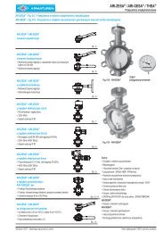
ContentsOverviewChapter/PageGeneral 00/01Applications, General design features 00/02Valve finder 00/03Valve selection 00/05How to use:Signs and symbols, Flange drillings and facings 00/07How to use:Determination of coefficient of discharge K dr /α w 00/08How to use: Capacity sheets 00/09LESER Effective Orifice LEO S/G 00/11LESER Effective Orifice LEO L 00/12Sour gas service 00/13<strong>Type</strong> <strong>441</strong>, <strong>442</strong> ANSI 02/01Materials• Conventional design 02/02• Balanced bellows design 02/04How to order• Numbering system 02/06• <strong>Ar</strong>ticle numbers 02/08Dimensions and weights• Metric Units 02/10• US Units 02/11Pressure temperature ratings• Metric Units 02/12• US Units 02/13Flange drillings and facings 02/14Order information – Spare parts 02/15Available options 02/16Approvals 02/17Capacities• Steam [Metric Units + US Units] 02/18• Air [Metric Units + US Units] 02/19• Water [Metric Units + US Units] 02/20Determination of coefficient of discharge K dr /αw 02/21LESER <strong>Type</strong>Chapter/Page<strong>Type</strong> <strong>441</strong>, <strong>442</strong> <strong>DIN</strong> 01/01Materials• Conventional design 01/02• Balanced bellows design 01/04How to order• Numbering system 01/06• <strong>Ar</strong>ticle numbers 01/08Dimensions and weights• Metric Units 01/10• US Units 01/11Pressure temperature ratings• Metric Units 01/12• US Units 01/14Flange drillings and facings 01/16Order information – Spare parts 01/18Available options 01/20Approvals 01/21Capacities• Steam [Metric Units + US Units] 01/22• Air [Metric Units + US Units] 01/24• Water [Metric Units + US Units] 01/26Determination of coefficient of discharge K dr /αw 01/28<strong>Type</strong> <strong>441</strong>, <strong>442</strong> XXL 03/01Materials• Conventional design 03/02• Balanced bellows design 03/04How to order• Numbering system 03/06• <strong>Ar</strong>ticle numbers 03/08Dimensions and weights• Metric Units 03/10• US Units 03/11Pressure temperature ratings• Metric Units 03/12• US Units 03/13Flange drillings and facings 03/14Order information – Spare parts 03/15Available options 03/16Approvals 03/17Capacities• Steam [Metric Units + US Units] 03/18• Air [Metric Units + US Units] 03/19• Water [Metric Units + US Units] 03/20Determination of coefficient of discharge K dr /αw 03/21<strong>Type</strong> <strong>441</strong>Cap H2Closed bonnetConventional design<strong>Type</strong> <strong>441</strong>Packed lever H4Closed bonnetConventional design<strong>Type</strong> <strong>441</strong>Plain lever H3Closed bonnetConventional design<strong>Type</strong> 444Packed lever H4Closed bonnetConventional design<strong>Type</strong> <strong>441</strong>Cap H2Closed bonnetBalanced bellows design<strong>Type</strong> <strong>442</strong>Plain lever H3Open bonnetConventional design<strong>Type</strong> 444Cap H2Closed bonnetConventional design
Contents<strong>Type</strong> 444 <strong>DIN</strong> 04/01Materials• Conventional design 04/02How to order• Numbering system 04/04• <strong>Ar</strong>ticle numbers 04/06Dimensions and weights• Metric Units + US Units 04/07Pressure temperature ratings• Metric Units + US Units 04/08Flange drillings and facings 04/09Order information – Spare parts 04/10Available options 04/11Approvals 04/12Capacities• Steam [Metric Units + US Units] 04/13• Air [Metric Units + US Units] 04/14• Water [Metric Units + US Units] 04/15Determination of coefficient of discharge K dr /αw 04/16<strong>Type</strong> 444 ANSI 05/01Materials• Conventional design 05/02How to order• Numbering system 05/04• <strong>Ar</strong>ticle numbers 05/06Dimensions and weights• Metric Units + US Units 05/07Pressure temperature ratings• Metric Units + US Units 05/08Flange drillings and facings 05/09Order information – Spare parts 05/10Available options 05/11Approvals 05/12Capacities• Steam [Metric Units + US Units] 05/13• Air [Metric Units + US Units] 05/14• Water [Metric Units + US Units] 05/15Determination of coefficient of discharge K dr /αw 05/16Options 99/01Overview 99/02Caps and Levers 99/04Caps and Levers bolted 99/06Metal seat 99/08Soft seal disc 99/10OptionsSoft seal 99/12Balanced bellows 99/14High temperature equipment 99/16Elastomer bellows 99/17Disc 99/18Heating jacket 99/20O-ring damper 99/22Lift indicator 99/24Lift restriction 99/25<strong>Type</strong> <strong>441</strong>, <strong>442</strong> Full nozzleMaterialsHow to orderDimensions and weightsPressure temperature ratingsFlange drillings and facingsOrder information – Spare partsAvailable optionsApprovalsCapacitiesDetermination of coefficient of discharge K dr /α w<strong>Type</strong> 455, 456MaterialsHow to orderDimensions and weightsPressure temperature ratingsFlange drillings and facingsOrder information – Spare partsAvailable optionsApprovalsCapacitiesDetermination of coefficient of discharge K dr /α w<strong>Type</strong> 457, 458MaterialsHow to orderDimensions and weightsPressure temperature ratingsFlange drillings and facingsOrder information – Spare partsAvailable optionsApprovalsCapacitiesDetermination of coefficient of discharge K dr /α wrefer to catalogSeries <strong>441</strong> Full nozzlerefer to catalogSeries 458refer to catalogSeries 458refer to catalogSeries <strong>441</strong> Full nozzlerefer to catalogSeries 458refer to catalogSeries 458refer to catalogSeries 458<strong>Type</strong> <strong>441</strong> XXLBolted lifting device H6Closed bonnetConventional and balancedbellows design<strong>Type</strong> <strong>441</strong> Full NozzleCap H2Closed bonnetConventional design<strong>Type</strong> 456Packed lever H4Closed bonnetConventional design<strong>Type</strong> 457Plain lever H3Open bonnetConventional design<strong>Type</strong> 458Cap H2Closed bonnetBalanced bellows design
GeneralGeneral InformationLESER – High Performance Safety ValvesThe High Performance product group represents✓ High capacity related to the safety valve size✓ High adaptability✓ Excellent price / performance ratioLESER´s High Performance Safety Valves• <strong>Ar</strong>e designed to meet all industrial applications.• Open rapidly with an overpressure of 5 % to the full design lift.• <strong>Ar</strong>e used particularly for vapours and gases wherethe maximum mass flow has to be discharged rapidly.• Have a maximum blowdown of minus 10 % for steam/gas service and minus 20 % for liquid service.• <strong>Ar</strong>e one of the best selling spring loaded safety valveworldwide.• <strong>Ar</strong>e developed in a close cooperation with plant engineersand service specialists.• Serve for protection of processes and equipment.• <strong>Ar</strong>e approved by all important approval organisations worldwidewhich ensures the worldwide applicability e.g.:• European Community: CE-marking acc. to PressureEquipment Directive (PED) 97 / 23 / EC and EN ISO 4126-1• USA: UV-stamp acc. to ASME Section VIII Division 1,National Board certified capacities• Germany: VdTÜV approval acc. to PED, EN ISO 4126-1,TÜV SV 100 and AD 2000-Merkblatt A2• Canada: Canadian Registration Number acc. to therequirements of particular provinces• China: AQSIQ based on the approval acc. to ASMESection VIII Division 1 and AD 2000-Merkblatt A2Furthermore, all LESER High Performance safety valvesare designed, marked, produced and approved acc. to therequirements of the following regulations (directives, codes,rules and standards).EN ISO 4126-7, EN 12266-1/-2, EN 1092 Part I and II flangingASME PTC 25, ASME-Code Sec. II, ASME B 16.34 and ASMEB16.5-flanging, API Std. 527, API RP 576AD 2000-Merkblatt A4, AD 2000-Merkblatt HP0, TRD 110,TRD 421, TRD 72100/01 LWN 482.01-E
General InformationGeneralApplicationsLESER – High Performance Safety Valves<strong>Ar</strong>e the ultimate solution for all industrialapplications for steam, gas and liquid.Typical applications forLESER High Performance Safety Valves are:Series <strong>441</strong>• Protection of chemical processes and equipment(e.g. distillation columns)• Heat exchangers• Low and medium pressure steam• Blowers and turbo compressorsSeries XXL• Low pressure steam at big power stations• Capacities beyond the limits of API and Series <strong>441</strong>Series 444• OEM in dying machines or filter constructions• Stainless steel applications up to 16 bar / 232 psigSeries <strong>441</strong> Full Nozzle• Same applications like Series <strong>441</strong> whenfull nozzle design is preferred.• Special requirement for nozzle materialSeries 458• Power stations and industrial superheatedsteam generation• Required flange classes ≥ PN 63 / CL600• Protection of high pressure Chemical processes,e.g. NH 3 synthesis, CO 2 extraction• Desalination plantsGeneral Design FeaturesLESERs High Performance Safety ValvesOffer a large variety of types, materials and optionsto suit any application:• 14 valve sizes from DN 20 to DN 400 – 3 /4" to 16"provide a high connectivity to the application• Inlet pressure ratings PN 16 to PN 400 / class 150 toclass 2500 to fit all required design pressures• Orifice sizes from E to > 3 x T cover all capacityrequirements• Large variety of body materials; e.g.• 0.6025 / grey iron• 0.7043 / ductile iron• 1.0619 / WCB• 1.4408 / CF8M• 1.7357 / WC6can be selected acc. to the application• Set pressures from 0.1 to 300 bar / 1.5 to 4350 psigmake this product group suitable for all industrial processes• Operating temperatures from -270 to 550 °C / -454 to1022 °F cover a wide range of applications• One design and spring (single trim) for steam, gas andliquid applications reduces the number of spare parts andensure an easier maintenance• High capacity compared to the API requirements to reduceinstallation costs• Ringless design needs no trim adjustmentsfor easy maintenance• One-piece spindle reduces friction which is leading tohigh operation accuracy• Self-draining body design, avoids residues and reducescorrosionLESERs High Performance Safety Valvescan be customized with a great variety of options, e.g.• O-ring disc for superior tightness• Stellited or hardened metal sealing for longer product life• Stainless steel bellows for back pressure compensation• Heating jacket for applications with high viscosity fluids• Every part can be replaced by other material acc. tocustomer specificationLWN 482.01-E00/02
GeneralValve finderHow to find the right Product GroupHigh operating to setpressure ratio, high backpressureor low total height?YesHighEfficiencyMediumcontrolledNoClean Serviceapplication?YesCleanServiceNoCritical Service / highly corrosiveapplication?YesCriticalServiceNoAPI specifiedapplication?NoSteam, gas and liquid applicationwith low capacity in relationto the valve size?YesYesAPIModulateActionSpring loadedSafety ValvesNoOrifice ≥ FHighPerformanceRequiredOrifice letter?Orifice ≤ FCompactPerformanceAdditional componentsbeyond safety valvesYesBestAvailabilityChangeovervalveBurstingdisc00/03 LWN 482.01-E
Valve finderHow to find the right Safety ValveGeneral<strong>DIN</strong> EN 1092<strong>Type</strong> <strong>441</strong> <strong>DIN</strong><strong>Type</strong> <strong>442</strong> <strong>DIN</strong>Flange standard?ASME B16.5<strong>Type</strong> <strong>441</strong> ANSI<strong>Type</strong> <strong>442</strong> ANSINo<strong>DIN</strong> EN 1092<strong>Type</strong> <strong>441</strong> Full nozzle <strong>DIN</strong><strong>Type</strong> <strong>442</strong> Full nozzle <strong>DIN</strong>Full nozzle-design required?YesASME B16.5<strong>Type</strong> <strong>441</strong> Full nozzle ANSI<strong>Type</strong> <strong>442</strong> Full nozzle ANSI≤ PN40 / CL300≥ PN63 / ≥ CL600Serie 458Flange rating?≤ DN 150 / 6"Semi nozzle up to100 bar / 1450 psigFull nozzle up to400 bar / 5800 psig<strong>Type</strong> 455<strong>Type</strong> 456<strong>Type</strong> 457<strong>Type</strong> 458Valve size, inlet?≥ DN 200 / 8"<strong>Type</strong> <strong>441</strong> XXL<strong>Type</strong> <strong>442</strong> XXLGeneral industryStainless steelOEM-application?up to16 bar /232 psig<strong>DIN</strong> EN 1092ASME B16.5<strong>Type</strong> 444 <strong>DIN</strong><strong>Type</strong> 444 ANSIHow to findthe right Hig PerformanceSafety ValveLWN 482.01-E00/04
GeneralValve selectionValve size<strong>Type</strong> <strong>441</strong>, <strong>442</strong><strong>DIN</strong><strong>441</strong>, <strong>442</strong>ANSI<strong>441</strong>, <strong>442</strong>XXL444<strong>DIN</strong>444ANSI<strong>441</strong>, <strong>442</strong>Full nozzle<strong>DIN</strong><strong>441</strong>, <strong>442</strong>Full nozzleANSI455, 456 457, 458min.max.DN 20 (DN 25) DN 200 DN 25 – DN 25 (DN 25) DN 25 DN 25( 3 / 4 ") 1" 8" – 1" (1") 1" 1" 1"DN 200 (DN 100) DN 400 DN 80 – DN 50 (DN 100) DN 100 DN 150(8") 4" 16" – 3" (2") 4" 4" 6"Materials<strong>Type</strong> <strong>441</strong>, <strong>442</strong><strong>DIN</strong><strong>441</strong>, <strong>442</strong>ANSI<strong>441</strong>, <strong>442</strong>XXL444<strong>DIN</strong>444ANSI<strong>441</strong>, <strong>442</strong>Full nozzle<strong>DIN</strong><strong>441</strong>, <strong>442</strong>Full nozzleANSI455, 456 457, 4580.6025 Grey iron ✓ – – – – – – – –0.7043 Ductile Gr. 60-40-18 ✓ – – – – – – – –1.0619 WCB ✓ ✓ – – – ✓ ✓ ✓ ✓1.0460 / 1.0425 Carbon steel – – ✓ – – – – – –1.4408 CF8M ✓ ✓ – – – ✓ ✓ – –1.4404 316L – – – ✓ ✓ – – – –1.4581 CF10M – – – – – – – ✓ ✓1.4571 316Ti – – ✓ – – – – – –1.7357 WC6 – – – – – – – ✓ ✓Set pressure<strong>Type</strong> <strong>441</strong>, <strong>442</strong><strong>DIN</strong><strong>441</strong>, <strong>442</strong>ANSI<strong>441</strong>, <strong>442</strong>XXL444<strong>DIN</strong>444ANSI<strong>441</strong>, <strong>442</strong>Full nozzle<strong>DIN</strong><strong>441</strong>, <strong>442</strong>Full nozzleANSI455, 456 457, 458Metric Units min. [bar] 0.1 0.1 0.2 0.1 0.1 0.1 0.1 2.5 2.5US Units min. [psig] 1.5 3 3 1.5 1.5 1.5 1.5 36 36Metric Units max. [bar] 40 51 25 16 16 40 51 100 300US Units max. [psig] 580 740 360 232 232 580 740 1450 435000/05 LWN 482.01-E
Valve selectionGeneralTemperature range<strong>Type</strong> <strong>441</strong>, <strong>442</strong><strong>DIN</strong><strong>441</strong>, <strong>442</strong>ANSI<strong>441</strong>, <strong>442</strong>XXL444<strong>DIN</strong>444ANSI<strong>441</strong>, <strong>442</strong>Full nozzle<strong>DIN</strong><strong>441</strong>, <strong>442</strong>Full nozzleANSI455, 456 457, 458acc. to <strong>DIN</strong> EN min. [°C] -270 -270 -196 -45 -45 -270 -270 -85 -270max. [°C] 450 450 550 200 200 450 450 550 550min. [°F] -454 -454 -321 -49 -49 -454 -454 -121 -454max. [°F] 842 842 1022 392 392 842 842 1022 1022acc. to ASME min. [°C] -268 -268 -184 -45 -45 -268 -268 -129 -268max. [°C] 538 538 427 200 200 538 538 538 538min. [°F] -450 -450 -300 -49 -49 -450 -450 -20 -450max. [°F] 1000 1000 800 392 392 1000 1000 1000 1000Capacity<strong>Type</strong> <strong>441</strong>, <strong>442</strong><strong>DIN</strong><strong>441</strong>, <strong>442</strong>ANSI<strong>441</strong>, <strong>442</strong>XXL444<strong>DIN</strong>444ANSI<strong>441</strong>, <strong>442</strong>Full nozzle<strong>DIN</strong><strong>441</strong>, <strong>442</strong>Full nozzleANSI455, 456 457, 458LEOS/G min. 0.283 0.462 23.8 0.462 0.462 0.462 0.462 0.399 0.224LEOS/G max. 23.8 7.39 76.0 4.78 4.78 1.85 7.39 5.46 11.4OrificeS/G min. 1.4 x E 1.5 x F 1.5 x R 1.5 x F 1.5 x F 1.5 x F 1.5 x F 1.3 x F 1.1 x EOrificeS/G max. 1.5 x R 1.2 x P 3.0 x T 1.1 x N 1.1 x N 1.0 x K 1.2 x P 1.3 x N 1.0 x QLEOL min. 0.316 0.516 26.6 0.516 0.516 0.516 0.516 0.429 0.241LEOL max. 26.6 8.26 84.9 5.34 5.34 2.07 8.26 5.87 10.9OrificeL min. 1.0 x F 1.0 x G 1.0 x T 1.0 x G 1.0 x G 1.0 x G 1.0 x G 1.4 x F 1.2 x EOrificeL max. 1.0 x T 1.3 x P 33 x T 1.2 x N 1.2 x N 1.1 x K 1.3 x P 1.4 x N 1.7 x PApprovals<strong>Type</strong> <strong>441</strong>, <strong>442</strong><strong>DIN</strong>Country Code Media<strong>441</strong>, <strong>442</strong>ANSI<strong>441</strong>, <strong>442</strong>XXL444<strong>DIN</strong>444ANSI<strong>441</strong>, <strong>442</strong>Full nozzle<strong>DIN</strong><strong>441</strong>, <strong>442</strong>Full nozzleANSI455, 456 457, 458EuropeGermanyUnitedStates<strong>DIN</strong> EN ISO 4126-1CE-markingAD 2000-Merkblatt A2ASME VIIIS/G/L 07 202 0111Z0008/0/08 Rev. 3S/G/LTÜV SV576TÜV SV576TÜV SV576TÜV SV576TÜV SV576TÜV SV576TÜV SV576S/G M37044 M37044 M37044 M37044 M37044 M37044 M37044L M37055 M37055 M37055 M37055 M37055 M37055 M3705507 202 0111Z0008/0/11Rev. 1TÜV SV934M37066M37088M37077M37099Canada CRN S/G/L ✓ ✓ ✓ ✓ ✓ ✓ ✓ – –China AQSIQ S/G/L ✓ ✓ ✓ ✓ ✓ ✓ ✓ ✓ ✓Russia GOST R / RTN ✓ ✓ ✓ ✓ ✓ – – ✓ ✓Classification societiesBureau Veritas BV ✓ ✓ ✓ – – – – – –Det Norske Veritas DNV ✓ ✓ – – – – – – –Germanischer Lloyd GL ✓ ✓ ✓ – – – – – –Lloyd`s register EMEA LREMEA ✓ ✓ ✓ – – – – – –Registro Italiano Navale RINA ✓ ✓ up to DN 250 – – – – – –TÜV SV934M37066M37088M37077M37099LWN 482.01-E00/06
GeneralHow to useGeneral signs and symbolsThis option is covered by standard design*✓ Available–Not possibleSigns and symbols for flange drillings and flange facingsStandard design, no option code required*–Flange drilling/facing is not possible( * )Flange dimensions except flange thickness are in accordance with flange standard (e.g. ASME B16.5)Flange thickness is smaller (max. 2 mm), see “Multiple pressure rating”.Option code for flange drilling and dimension, e.g. H50H50(H50)[H50]Flange drilling as specified in flange standardOuter flange diameter, flange thickness and height of flange facing may be larger, see “Dimensions”Flange dimensions except flange thickness are in accordance with standardFlange thickness is smaller (max. 2 mm), see “Multiple pressure rating”Flange drilling as specified in standard/flange thickness may be smallerOuter flange diameter is smaller than required, but complete back side facing for nut is assuredOption code for flange facing, e.g. L36L36Flange facing as specified in flange standard (e.g. Flange facing inlet <strong>Type</strong> B2 “smooth finish”)General information concerning flange drillings and flange facingsMultiplepressure ratingSmooth finishStock finishThe flange standard shows the same drilling, facing and outer diameter for several pressure ratings, e.g. PN 16 up to PN 40Due to the pressure rating of the casting LESER fulfils the requirements for flange thickness e.g. of PN 16 but not PN 40The effective MSS SP-6 (Edition 2001) does not mention “smooth finish” anymore.In MSS SP-6 (Edition 1980) “smooth finish” is defined for finishes of contact flanges as “250 µinch (6.3 µm) AARH max.”.LESER supplies flange facings according to ASME B16.5 – 1996, paragraph 6.4.4.3:“Either a serrated concentric or serrated spiral finish resulting in service finish from 125 µinch to 250 µinch averageroughness shall be furnished.” This finish meets the requirements of MSS SP-6 (Edition 1980), which is not valid anymore!Stock finish is not defined in any technical standard. If purchase orders show “stock finish” LESER supplies standardfacing according to <strong>DIN</strong> or ASME (marked with * in table “Flange facings” of each valve series).MaterialsPlease find below a summary of material codes at LESER. Please note that- for every body material an inspection certificate 3.1 according to EN 10204 is available- many materials have a multiple inspection certificate 3.1.Material codeFlanged safety valve bodyBody material is certified with 3.1 (EN 10204) for the following materials<strong>DIN</strong> ENASMExxx 1.xxxx Grey iron 0.6025 cast ironxxx 2.xxxx Carbon steel 1.0619 WCB, WCCxxx 4.xxxx Stainless steel 1.4408, 1.4581 CF8M (Charpy test at -196°C), CF10Mxxx 5.xxxx Nodular cast iron 0.7043 ductile Gr. 60-40-18xxx 7.xxxx High temperature carbon steel 1.7357 WC600/07 LWN 482.01-E
How to useSample Determination of K dr /α w : <strong>Type</strong> <strong>441</strong>, <strong>DIN</strong>, DN 25General<strong>Type</strong> <strong>441</strong>, <strong>442</strong> <strong>DIN</strong>Determination of coefficient of dischargein case of lift restriction or back pressureDiagram for evaluation of ratio of lift / flow diameter (h/d0)in reference to the coefficient of discharge (Kdr/αw)10.800K dr = α w = f (h/d 0)h = Lift [mm]d 0 = Flow diameter [mm] of selected safetyvalve, refer to table article numbersh/d 0 = Ratio of lift / flow diameterp a0 = Back pressure [bar a]p 0 = Set pressure [bar a]p a0 /p 0 = Ratio of back pressure / set pressureK dr = Coefficient of dischargeacc. to <strong>DIN</strong> EN ISO 4126-1α w = Coefficient of dischargeacc. to AD 2000-Merkblatt A2K b = Back pressure correction factoracc. to API 520 topic 3.30.700DN 20 – 100 S/G1a0.45Coefficient of discharge Kdr / αwDN 200 cast S/G0.600DN 125 – 150, S/G0.500DN 200 cast L0.400DN 20 – 100 L0.300DN 125 – 150, L0.2000.10000 0.050 0.100 0.150 0.200 0.250 0.3000.21 0.243 0.270Ratio of lift / flow diameter h / d 01b 0.13Diagram for evaluation of coefficient of discharge (Kdr/αw) or Kbin reference to the ratio of back pressure / set pressure (pa0/p0)20.8K dr = α w = f (p a0/p 0) and K b = f (p a0/p 0)2b0.595Coefficient of discharge K dr / αw0.70.60.50.40.30.20.100.2 0.3 0.4 0.5 0.6 0.7 0.8Ratio of back pressure / set pressure pa0 / p02a 0.6480.911.00.90.80.70.60.50.40.30.20.100.85Back pressure correction factor Kb2bExplanationSample – <strong>Type</strong> <strong>441</strong> <strong>DIN</strong>, DN 25, flow diameter d 0 = 23 mm, rated lift h = 5.6 mm, K dr /α w S/G = 0.71Diagram 1Diagram 22Determination of the restricted lift due to reduced K dr /α w Determination of reduced K dr /α w or K 1) b due to back pressureStep Description Sample Step Description SampleCalculate the required coefficent of discharge of 1aCalculate the back pressure ratio pa0/p 0 using the1 the selected safety valve. Applicable formulars1 actual values for set pressure p 0 [bar a ] 0.45are stated in codes and standards.K dr /α w = 0.45 and back pressure pa0 [bar a ] 0.292 p a0 /p 2a 0 = 0.6482Select the starting point (0.45) at the Y-axis ofthe diagram.2Select the starting point (0.648) at the X-axisof the diagram.3Lay a horizontal line onto the ratio graph toidentify the intersection point.3Lay a vertical line onto the ratio graph toidentify the intersection point.45Lay a vertical line to the X-axis to identify theratio of lift / flow diameter (h/d 0 ).Calculate the restricted lift using the formularh = d 0 x h/d 0 . (For ordering a lift restrictionplease use option code J51 refer to page 99/25)1bLay a horizontal line to the Y-axis toK dr /α w = 0.59542bh/d 0 = 0.13 identify the reduced K dr /α w or K b .K b = 0.85h = 23 x 0.13h = 3 mm5Calculate the sizing with the establishedK dr /α w or K b .1) Back pressure correction factor Kb acc. to API 520 topic 3.3. For further information refer to ENGINEERING at www.leser.com/engineering.LWN 482.01-E00/08
GeneralHow to useSample Capacity sheet –How to select capacities for steam: <strong>Type</strong> <strong>441</strong> XXL <strong>DIN</strong>, DN 250Capacities – SteamCapacities for saturated steam according to AD 2000-Merkblatt A2,based on set pressure plus 10 % overpressure.9Capacities at 1 bar (14.5 psig) and below are based on 0.1 bar(1.45 psig) overpressure.Metric Units1AD 2000-Merkblatt A2 [kg/h]DNI+O 200 x 300 250 x 350 2 300 x 400 400 x 500Valve size 8" x 12" 3 10" x 14" 12" x 16" 16" x 20"Act. Orifice dia. d 0 [mm] 165 200 4 235 295Act. Orifice area. d 0 [mm] 21382 5 31416 43374 68349LEOS/G* ) [inch 2 ] 23.761 34.910 6 48.198 75.952Set pressure [bar] 7 Capacities [kg/h]0.1 0 0 0 00.2 7214 0 14633 00.5 11516 16920 23360 368111 16755 24617 8 33986 53556Capacities for saturated steam according to ASME Section VIII (UV),based on set pressure plus 10% overpressure.Capacities at 2.07 bar (30 psig) and below are based on 0.207 bar(3 psig) overpressure.US Units ASME Section VIII [lb/h]DN I+O 200 x 300 250 x 350 300 x 400 400 x 500Valve size 8" x 12" 10" x 14" 12" x 16" 16" x 20"Act. Orifice dia. d 0 [inch] 6.5 7.87 9.25 11.61Act. Orifice area. d 0 [inch 2 ] 33.14 48.69 67,23 105.94LEO S/G * ) [inch 2 ] 23.761 34.910 48.198 75.952Set pressure [psig]Capacities [lb/h]15 38962 57245 79034 12454320 44928 66009 91134 14361230 56859 83539 115336 18174940 69983 102821 141958 223700* ) LEO S/G = LESER Effective Orifice steam/gas please refer to page 00/11Explanation <strong>Type</strong> <strong>441</strong> XXLNo. Description Metric Units US Units Example1Code AD 2000-Merkblatt A22Nominal diameter inlet x outlet DNI+O 250 x 3503Valve size 10" x 14"4Actual orifice diameter d 0 [mm] [inch] 2005Actual orifice area A 0 [mm 2 ] [inch 2 ] 314166LESER Effective Orifice LEO S/G [inch 2 ] [inch 2 ] 34.9107Set pressure [bar g ] [psig] 18Capacity [kg/h] [lb/h] 246179Base of calculation see table page 00/1000/09 LWN 482.01-E
How to useGeneral9Base of calculationMetric UnitsUS UnitsCodeCapacity calculation according toAD 2000-Merkblatt A2Capacity calculation according toASME Section VIII (UV)STEAM(saturated steam)StandardconditionsSteam table IAPWS-IF97IAPWS Industrial Formulation forthe Thermodynamic Propertiesof Water and Steam[kg/h]Steam table IAPWS-IF97IAPWS Industrial Formulation forthe Thermodynamic Propertiesof Water and Steam[lb/h]AIRStandardconditions0 °C and 1013 mbar [m n 3 /h] 16 °C (60 °F) [S.C.F.M.]WATERStandardconditions20 °C (68 °F) [10 3 kg/h] 21 °C (70 °F) [US-G.P.M.]CalculationpressureSet pressure plus 10 % overpressureSet pressure plus 10 % overpressureCalculationpressurefor lowset pressureCapacities at 1 bar (14.5 psig)and below are based on 0.1 bar(1.45 psig) overpressure.Capacities at 2.07 bar (30 psig)and below are based on0.207 bar (3 psig) overpressure.Example Capacity calculation pressureMetric UnitsUS UnitsSet pressure Capacity calculation pressure Set pressure Capacity calculation pressure10 bar 10 bar + 10% overpressure = 11 bar 145 psig 145 psig + 10% overpressure = 159.5 psig0.5 bar 0.5 bar + 0.1 bar overpressure = 0.6 bar 20 psig 20 psig + 3 psig overpressure = 23 psig6LESER Effective OrificePressure relief devices may be initially sized using the equationsshown in API RP 520, sections 3.6 through 3.10 asappropriate for vapors, gases, liquids, or two phase flow.These equations utilize effective coefficient of discharge (S/G0.975, L 0.650) and effective areas (acc. to API Std. 526, FifthEdition, June 2002, table 1) which are independent of anyspecific valve design. In this way the designer can determinea preliminary pressure relief valve size. By using theLESER Effective Orifice the designer can directly select aLESER safety relief valve after calculating the orifice letter. Inthis case, a verification of the sizing with the selected actualorifice and the rated coefficient of discharge is not necessary.LEO S/GLESER Effective Orifice (for steam, gas and vapor) [inch 2 ] refer to page 00/11LEO LLESER Effective Orifice (for liquid) [inch 2 ] refer to page 00/12For further information refer to LESER Engineering Handbook.LWN 482.01-E00/10
GeneralLEOS/GThis table is based on the rated coefficient of discharge for steams and gases of LESER safety valves certified by ASME.The appropriated K-values are shown in the column “K-value” of the table.LEO S/G [inch 2 ] = A 0 [inch 2 ] . ( K ) 0.975Orifice acc.API 526LEOS/GLESER Effective Orifice (for steam, gas and vapor)LESER-Series DN Inlet size d 0 [inch] d 0 [mm] K-valueLEOS/G[inch 2 ]% of nexthigherorifice% of nextlowerorificeD 0.110 100.0% 100.0%E 0.196 100.0% 100.0%458 25 1" 0.591 15.0 0.798 0.224 73.0% 114.4%<strong>441</strong> 20 3/ 4 " 0.709 18.0 0.699 0.283 92.1% 114.3%F 0.307 100.0% 100.0%458 25 1" 0.787 20.0 0.798 0.399 79.2% 129.8%<strong>441</strong> 25 1" 0.906 23.0 0.699 0.462 91.8% 150.4%<strong>441</strong> Full nozzle 25 1" 0.906 23.0 0.699 0.462 91.8% 150.4%444 25 1" 0.906 23.0 0.699 0.462 91.8% 150.4%G 0.503 100.0% 100.0%<strong>441</strong> 32 1 1/ 2 " 1.142 29.0 0.699 0.734 93.5% 145.9%<strong>441</strong> Full nozzle 32 1 1/ 2 " 1.142 29.0 0.699 0.734 93.5% 145.9%H 0.785 100.0% 100.0%458 50 2" 1.181 30.0 0.798 0.897 69.7% 114.2%<strong>441</strong> 40 1 1/ 2 " 1.457 37.0 0.699 1.195 92.8% 152.2%<strong>441</strong> Full nozzle 40 1 1/ 2 " 1.457 37.0 0.699 1.195 92.8% 152.2%444 40 1 1/ 2 " 1.457 37.0 0.699 1.195 92.8% 152.2%J 1.287 100.0% 100.0%457. 458 50 2" 1.575 40.0 0.798 1.594 86.7% 123.9%K 1.838 100.0% 100.0%<strong>441</strong> 50 2" 1.811 46.0 0.699 1.847 64.7% 100.5%<strong>441</strong> Full nozzle 50 2" 1.811 46.0 0.699 1.847 64.7% 100.5%444 50 2" 1.811 46.0 0.699 1.847 64.7% 100.5%458 80 3" 1.969 50.0 0.798 2.491 87.3% 135.5%458 100 4" 1.969 50.0 0.798 2.491 87.3% 135.5%L 2.853 100.0% 100.0%<strong>441</strong> 65 3" 2.362 60.0 0.699 3.142 87.3% 110.1%<strong>441</strong> Full nozzle 65 3" 2.362 60.0 0.699 3.142 87.3% 110.1%444 65 2 1/ 2 " 2.362 60.0 0.699 3.142 87.3% 110.1%458 80 3" 2.362 60.0 0.754 3.389 94.1% 118.1%458 100 4" 2.362 60.0 0.798 3.587 99.6% 125.7%M 3.600 100.0% 100.0%N 4.340 100.0% 100.0%<strong>441</strong> 80 – 2.913 74.0 0.699 4.779 74.9% 110.1%444 80 3" 2.913 74.0 0.699 4.779 74.9% 110.1%458 100 4" 2.913 74.0 0.798 5.456 85.5% 125.7%P 6.380 100.0% 100.0%458 100 4" 3.465 88.0 0.754 7.290 66.0% 114.3%<strong>441</strong> 100 4" 3.622 92.0 0.699 7.387 66.9% 115.8%<strong>441</strong> Full nozzle 100 4" 3.622 92.0 0.699 7.387 66.9% 115.8%<strong>441</strong> 125 5" 3.858 98.0 0.699 8.382 75.9% 131.4%Q 11.050 100.0% 100.0%458 150 6" 4.331 110.0 0.754 11.391 71.2% 103.1%<strong>441</strong> 150 6" 4.921 125.0 0.699 13.637 85.2% 123.4%R 16.000 100.0% 100.0%<strong>441</strong> 200 8" 6.496 165.0 0.699 23.761 91.4% 148.5%XXL 200 8" 6.496 165.0 0.699 23.761 91.4% 148.5%T 26.000 100.0% 100.0%XXL 250 10" 7.874 200.0 0.699 34.910 134.3%XXL 300 12" 9.252 235.0 0.699 48.198 185.4%XXL 400 16" 11.614 295.0 0.699 75.952 292.1%00/11 LWN 482.01-E
LEOLGeneralThis table is based on the rated coefficient of discharge for liquids of LESER safety valves certified by ASME.The appropriated K-values are shown in the column “K-value” of the table.LEO L [inch 2 ] = A 0 [inch 2 ] . (K) 0.650LEO LLESER Effective Orifice (for liquid)Orifice acc.API 526LESER-Series DN Inlet size d 0 [inch] d 0 [mm] K-valueLEOL[inch 2 ]% of nexthigherorifice% of nextlowerorificeD 0.110 100.0% 100.0%E 0.196 100.0% 100.0%458 25 1" 0.591 15 0.572 0.241 78.5% 123.0%F 0.307 100.0% 100.0%<strong>441</strong> 20 3/4" 0.709 18 0.521 0.316 62.9% 103.0%458 25 1" 0.787 20 0.572 0.429 85.2% 139.6%G 0.503 100.0% 100.0%<strong>441</strong> 25 1" 0.906 23 0.521 0.516 65.8% 102.6%<strong>441</strong> Full nozzle 25 1" 0.906 23 0.521 0.516 65.8% 102.6%444 25 1" 0.906 23 0.521 0.516 65.8% 102.6%H 0.785 100.0% 100.0%<strong>441</strong> 32 1 1/2" 1.142 29 0.521 0.821 6.38% 104.5%<strong>441</strong> Full nozzle 32 1 1/2" 1.142 29 0.521 0.821 6.38% 104.5%458 50 1" 1.181 30 0.572 0.964 74.9% 122.8%J 1.287 100.0% 100.0%<strong>441</strong> 40 1 1/2" 1.457 37 0.521 1.336 72.7% 103.8%<strong>441</strong> Full nozzle 40 1 1/2" 1.457 37 0.521 1.336 72.7% 103.8%444 40 1 1/2" 1.457 37 0.521 1.336 72.7% 103.8%458 50 2" 1.575 40 0.572 1.714 93.3% 133.2%K 1.838 100.0% 100.0%<strong>441</strong> 50 2" 1.811 46 0.521 2.065 72.4% 112.3%<strong>441</strong> Full nozzle 50 2" 1.811 46 0.521 2.065 72.4% 112.3%444 50 2" 1.811 46 0.521 2.065 72.4% 112.3%458 80 3" 1.969 50 0.527 2.678 93.9% 145.7%458 100 4" 1.969 50 0.527 2.678 93.9% 145.7%L 2.853 100.0% 100.0%458 80 3" 2.362 60 0.479 3.230 89.7% 113.2%<strong>441</strong> 65 3" 2.362 60 0.521 3.513 97.6% 123.1%<strong>441</strong> Full nozzle 65 3" 2.362 60 0.521 3.513 97.6% 123.1%444 65 1 1/2" 2.362 60 0.521 3.513 97.6% 123.1%M 3.600 100.0% 100.0%458 100 4" 2.362 60 0.572 3.857 88.9% 107.1%N 4.340 100.0% 100.0%<strong>441</strong> 80 – 2.913 74 0.521 5.343 83.3% 123.1%444 80 3" 2.913 74 0.521 5.343 83.3% 123.1%458 100 4" 2.913 74 0.572 5.866 91.9% 135.2%P 6.380 100.0% 100.0%458 100 4" 3.465 88 0.479 6.947 62.9% 108.9%<strong>441</strong> 100 4" 3.622 92 0.521 8.259 74.7% 129.4%<strong>441</strong> Full nozzle 100 4" 3.622 92 0.521 8.259 74.7% 129.4%<strong>441</strong> 125 5" 3.858 98 0.521 9.371 84.8% 146.9%458 150 6" 4.331 110 0.479 10.855 98.2% 170.1%Q 11.050 100.0% 100.0%<strong>441</strong> 150 6" 4.921 125 0.521 15.246 95.3% 138.0%R 16.000 100.0% 100.0%T 26.000 100.0% 100.0%<strong>441</strong> 200 8" 6.496 165 0.521 26.565 102.0%XXL 200 8" 6.496 165 0.521 39.031 102.0%XXL 250 10" 7.874 200 0.521 39.031 150.1%XXL 300 12" 9.252 235 0.521 53.887 207.3%XXL 400 16" 11.614 295 0.521 84.916 326.6%LWN 482.01-E00/12
GeneralSour gas service (H 2 S)Normative basisNACE MR0175-2003In accordance with NACE standard MR 0175-2003 sour gas servicemeans the presence of H 2 S in the following conditions:Section 1.4.1.1 All gas, gas condensate, and sour crude oil– When the partial pressure of H 2 S in a wet(water as a liquid) gas phase of a gas, gascondensate, or crude oil system is equal to orexceeds 0.003 bar a (0.05 psia)Exceptions are:Section 1.4.2.1 Low-pressure gasWhen the total pressure is lower than4.5 bar a (65 psia)Section 1.4.2.2 Low-pressure oil and gas multiphase systems: …Other Sour gas standards:NACE MR0103-2003: Materials resistance to sulfide stresscracking in corrosive petroleumrefining environments.<strong>DIN</strong> EN ISO 15156-1: Petroleum and natural gas industries– Materials for use in H 2 S containingenvironments in oil and gas production– Part 1: General principlesfor selection of cracking-resistantmaterials (ISO 15156-1:2001)Works standard: Please refer to LWN 001.91General requirements for sour gas serviceThe above mentioned standards require a maximum hardness of 22 HRC for the most steels.For the actual requirements of a specific material please refer to the applied standard.LESER sour gas levelGeneral: Sour gas material requirements must be fulfilled if pressure and partial pressure conditions according to the applied standard exist.Based on these general statement LESER defines two sour gas level for safety valves:Part definitionLevel 1 Level 2Contact with the medium inclosed positionContact with the medium inopened positionConventional Balanced bellows Conventional Balanced bellowsContact areaPressure requirements Set pressure ≥ 4,5 bar a (65 psia) Back pressure ≥ 4,5 bar a (65 psia)Safety valve operation closed closed / openedParts concernedConventionaldesignBalancedbellows designBody / NozzleDiscBody / NozzleDiscallBody / NozzleDisc,Bonnet spacer, BellowsNecessary material modificationBody<strong>Type</strong>Design Part Material Option code Material Option codematerial<strong>441</strong>2 <strong>DIN</strong>Conventional Disc 1.4404 / 316L L44 Please choose balanced bellows design<strong>441</strong>2 ANSI1.0619<strong>441</strong>2 Full nozzle <strong>DIN</strong> (WCB)Disc 1.4404 / 316L L44 1.4404 / 316L L44Balanced bellows<strong>441</strong>2 Full nozzle ANSI Balanced bellows 1.4571 / 316Ti J78 1.4571 / 316Ti J78<strong>441</strong>4 <strong>DIN</strong>Conventional No modification required No modification required<strong>441</strong>4 ANSI1.4408<strong>441</strong>4 Full nozzle <strong>DIN</strong> (CF8M)Balanced bellows Balanced bellows 1.4571 / 316Ti J78 1.4571 / 316Ti J78<strong>441</strong>4 Full nozzle ANSI<strong>441</strong>2 XXL<strong>441</strong>4 XXL1.0460/1.0425(Steel)1.4571(316Ti)4444 <strong>DIN</strong> 1.44044444 ANSI(316L)4562, 4582458745841.0619(WCB)1.7357(WC6)1.4581(CF10M)Conventional Disc No modification required Please choose balanced bellows designDisc No modification required No modification requiredBalanced bellowsBalanced bellows 1.4571 / 316Ti J78 1.4571 / 316Ti J78Conventional No modification required No modification requiredBalanced bellows Balanced bellows 1.4571 / 316Ti J78 1.4571 / 316Ti J78Conventional No modification required No modification requiredConventional Disc 1.4404 / 316L L44 Please choose balanced bellows designBalanced bellowsConventionalBalanced bellowsDisc 1.4404 / 316L L44 1.4404 / 316L L44Balanced bellows 1.4571 / 316Ti J78 1.4571 / 316Ti J78Not listed in NACENot listed in NACE00/13 LWN 482.01-E
<strong>Type</strong> <strong>442</strong> <strong>DIN</strong>Plain lever H3Open bonnetConventional design<strong>Type</strong><strong>441</strong> <strong>DIN</strong><strong>Type</strong> <strong>441</strong>, <strong>442</strong> <strong>DIN</strong><strong>442</strong> <strong>DIN</strong>Flanged Safety Relief Valves– spring loadedContentsChapter/Page<strong>Type</strong> <strong>441</strong> <strong>DIN</strong>Packed lever H4Closed bonnetConventional designMaterials• Conventional design 01/02• Balanced bellows design 01/04How to order• Numbering system 01/06• <strong>Ar</strong>ticle numbers 01/08Dimensions and weights• Metric Units 01/10• US Units 01/11Pressure temperature ratings• Metric Units 01/12• US Units 01/14Flange drillings and facings 01/16Order information – Spare parts 01/18Available options 01/20Approvals 01/21Capacities• Steam [Metric Units + US Units] 01/22• Air [Metric Units + US Units] 01/24• Water [Metric Units + US Units] 01/26Determination of coefficient 01/28of discharge K dr /α wLWN 482.01-E01/01
<strong>Type</strong> <strong>441</strong>, <strong>442</strong> <strong>DIN</strong>Conventional design<strong>Type</strong> <strong>441</strong>, <strong>442</strong> <strong>DIN</strong>40Cap H218Adjusting screw19Lock nut16Upper spring plate9 Bonnet12 Spindle54 Spring17Lower spring plate55 Stud56 Nut14 Split ring60 Gasket8Guide with bushing57 Pin61 Ball7 Disc5 Seat1 Body01/02 LWN 482.01-E
<strong>Type</strong> <strong>441</strong>, <strong>442</strong> <strong>DIN</strong>Conventional designMaterialsItem Component <strong>Type</strong> <strong>441</strong>1 / <strong>442</strong>1 <strong>DIN</strong> <strong>Type</strong> <strong>441</strong>5 / <strong>442</strong>5 <strong>DIN</strong> <strong>Type</strong> <strong>441</strong>2 / <strong>442</strong>2 <strong>DIN</strong> <strong>Type</strong> <strong>441</strong>4 <strong>DIN</strong><strong>Type</strong> <strong>441</strong>, <strong>442</strong> <strong>DIN</strong>1 Body5 Seat7 Disc8Guidewith bushing9 Bonnet12 Spindle14 Split ring16/17 Spring plate18Adjusting screwwith bushing19 Lock nut40 Cap H254Spring standardSpring optional55 Stud56 Nut57 Pin60 Gasket61 Ball0.6025 0.7043 1.0619 1.4408Cast iron Ductile Gr. 60-40-18 SA 216 WCB SA 351 CF8M1.4404 1.4404 1.4404 1.4404316L 316L 316L 316L1.4122 1.4122 1.4122 1.4404Hardened stainless steel Hardened stainless steel Hardened stainless steel 316L1.4104, 1.0501, 0.7040 1.4104, 1.0501, 0.7040 1.4104, 1.0501, 0.7040 1.4404Chrome or carbon steel Chrome or carbon steel Chrome or carbon steel 316L1.4104 tenifer 1.4104 tenifer 1.4104 tenifer –Chrome steel tenifer Chrome steel tenifer Chrome steel tenifer –0.7040, 0.7043, 1.0619 0.7040, 0.7043, 1.0619 0.7040, 0.7043, 1.0619 1.4408, 1.4404, 1.4571Ductile Gr. 60-40-18,SA 216 WCBDuctile Gr. 60-40-18,SA 216 WCBDuctile Gr. 60-40-18,SA 216 WCBSA 351 CF8M,SA 479 316L, SA 479 316Ti1.4021 1.4021 1.4021 1.440<strong>442</strong>0 420 420 316L1.4104 1.4104 1.4104 1.4404Chrome steel Chrome steel Chrome steel 316L1.0718 1.0718 1.0718 1.4404Steel Steel Steel 316L1.4104 PTFE 1.4104 PTFE 1.4104 PTFE 1.4404 PTFEChrome steel PTFE Chrome steel PTFE Chrome steel PTFE 316L PTFE1.0718 1.0718 1.0718 1.4404Steel Steel Steel 316L1.0718 or 0.7043 1.0718 or 0.7043 1.0718 or 0.7043 1.440412L13 or Gr. 60-40-18 12L13 or Gr. 60-40-18 12L13 or Gr. 60-40-18 316L1.1200, 1.8159, 1.7102 1.1200, 1.8159, 1.7102 1.1200, 1.8159, 1.7102 1.4310Carbon steel Carbon steel Carbon steel Stainless steel1.4310 1.4310 1.4310 –Stainless steel Stainless steel Stainless steel –1.1181 1.1181 1.1181 1.4401Steel Steel Steel B8M1.0501 1.0501 1.0501 1.44012H 2H 2H 8M1.4310 1.4310 1.4310 1.4310Stainless steel Stainless steel Stainless steel Stainless steelGraphite / 1.4401 Graphite / 1.4401 Graphite / 1.4401 Graphite / 1.4401Graphite / 316 Graphite / 316 Graphite / 316 Graphite / 3161.3541 1.3541 1.3541 1.4401Hardened stainless steel Hardened stainless steel Hardened stainless steel 316Please notice:- Modifications reserved by LESER- If several materials are specified LESER defines the material.- LESER can upgrade materials without notice.- Every part can be replaced by other material acc. to customer specification.LWN 482.01-E01/03
<strong>Type</strong> <strong>441</strong>, <strong>442</strong> <strong>DIN</strong>Balanced bellows design<strong>Type</strong> <strong>441</strong>, <strong>442</strong> <strong>DIN</strong>40181916Cap H2Adjusting screwLock nutUpper spring plate9 Bonnet12 Spindle54 Spring1417Split ringLower spring plate55 Stud56 Nut811Guide with bushingBonnet spacer60 Gasket22Lift stopper15 Bellows57 Pin61 Ball7 Disc5 Seat1 Body01/04 LWN 482.01-E
<strong>Type</strong> <strong>441</strong>, <strong>442</strong> <strong>DIN</strong>Balanced bellows designMaterialsItem Component <strong>Type</strong> <strong>441</strong>1 / <strong>442</strong>1 <strong>DIN</strong> <strong>Type</strong> <strong>441</strong>5 / <strong>442</strong>5 <strong>DIN</strong> <strong>Type</strong> <strong>441</strong>2 / <strong>442</strong>2 <strong>DIN</strong> <strong>Type</strong> <strong>441</strong>4 <strong>DIN</strong><strong>Type</strong> <strong>441</strong>, <strong>442</strong> <strong>DIN</strong>1 Body5 Seat7 Disc8Guidewith bushing9 Bonnet11 Bonnet spacer12 Spindle14 Split ring15 Bellows16/17 Spring plate18Adjusting screwwith bushing19 Lock nut22 Lift stopper40 Cap H254Spring standardSpring optional55 Stud56 Nut57 Pin60 Gasket61 Ball0.6025 0.7043 1.0619 1.4408Cast iron Ductile Gr. 60-40-18 SA 216 WCB SA 351 CF8M1.4404 1.4404 1.4404 1.4404316L 316L 316L 316L1.4122 1.4122 1.4122 1.4404Hardened stainless steel Hardened stainless steel Hardened stainless steel 316L1.4104, 1.0501, 0.7040 1.4104, 1.0501, 0.7040 1.4104, 1.0501, 0.7040 1.4404Chrome or carbon steel Chrome or carbon steel Chrome or carbon steel 316L1.4104 tenifer 1.4104 tenifer 1.4104 tenifer –Chrome steel tenifer Chrome steel tenifer Chrome steel tenifer –0.7040, 0.7043, 1.0619 0.7040, 0.7043, 1.0619 0.7040, 0.7043, 1.0619 1.4408, 1.4404, 1.4571Ductile Gr. 60-40-18,SA 216 WCBDuctile Gr. 60-40-18,SA 216 WCBDuctile Gr. 60-40-18,SA 216 WCBSA 351 CF8M,SA 479 316L, SA 479 316Ti1.0460 1.0460 1.0460 1.4404Carbon steel Carbon steel Carbon steel 316L1.4404 1.4404 1.4404 1.4404316L 316L 316L 316L1.4104 1.4104 1.4104 1.4404Chrome steel Chrome steel Chrome steel 316L1.4571 1.4571 1.4571 1.4571316Ti 316Ti 316Ti 316Ti1.0718 1.0718 1.0718 1.4404Steel Steel Steel 316L1.4104 PTFE 1.4104 PTFE 1.4104 PTFE 1.4404 PTFEChrome steel PTFE Chrome steel PTFE Chrome steel PTFE 316L PTFE1.0718 1.0718 1.0718 1.4404Steel Steel Steel 316L1.4404 1.4404 1.4104 1.4404316L 316L Chrome steel 316L1.0718 or 0.7043 1.0718 or 0.7043 1.0718 or 0.7043 1.440412L13 or Gr. 60-40-18 12L13 or Gr. 60-40-18 12L13 or Gr. 60-40-18 316L1.1200, 1.8159, 1.7102 1.1200, 1.8159, 1.7102 1.1200, 1.8159, 1.7102 1.4310Carbon steel Carbon steel Carbon steel Stainless steel1.4310 1.4310 1.4310 –Stainless steel Stainless steel Stainless steel –1.4401 1.4401 1.4401 1.4401B8M B8M B8M B8M1.4401 1.4401 1.4401 1.44018M 8M 8M 8M1.4310 1.4310 1.4310 1.4310Stainless steel Stainless steel Stainless steel Stainless steelGraphite / 1.4401 Graphite / 1.4401 Graphite / 1.4401 Graphite / 1.4401Graphite / 316 Graphite / 316 Graphite / 316 Graphite / 3161.3541 1.3541 1.3541 1.4401Hardened stainless steel Hardened stainless steel Hardened stainless steel 316Please notice:- Modifications reserved by LESER- If several materials are specified LESER defines the material.- LESER can upgrade materials without notice.- Every part can be replaced by other material acc. to customer specification.LWN 482.01-E01/05
<strong>Type</strong> <strong>441</strong>, <strong>442</strong> <strong>DIN</strong>How to order – Example for numbering system<strong>Type</strong> <strong>441</strong>, <strong>442</strong> <strong>DIN</strong>1<strong>Ar</strong>ticle Number2Set Pressure3Connections<strong>441</strong>2.4512 5 bar gH451 2 3 4<strong>441</strong> 2 . 451 2Please state unit (in gauge)!Please do not exceed the pressurerange defined in the spring charts.Please refer to page 01/16 and 01/1712Valve <strong>Type</strong> <strong>441</strong>, <strong>442</strong> <strong>DIN</strong><strong>Type</strong> <strong>441</strong> – with closed bonnet<strong>Type</strong> <strong>442</strong> – with open bonnetMaterial codeCodeLifting lever1 0.6025 (cast iron)2 1.0619 (WCB)4 1.4408 (CF8M)50.7043(ductile Gr. 60-40-18)3Valve codeIdentifies valve size and bodymaterial, refer to page 01/09.4CodeLifting lever2 screwed cap H23 plain lever H34 packed lever H45plain leverwith openbonnetH301/06 LWN 482.01-E
<strong>Type</strong> <strong>441</strong>, <strong>442</strong> <strong>DIN</strong>4 5 6Options Documentation Code and Medium<strong>Type</strong> <strong>441</strong>, <strong>442</strong> <strong>DIN</strong>J22 H01 L30 2.0<strong>Type</strong> <strong>441</strong>, <strong>442</strong> <strong>DIN</strong>Option codePlease select required documentation:1 2• O-ring-discCR “K” J21EPDM “D” J22FKM “L” J23FFKM “C” J20• Disc 1.4404 / 316LL44• Disc 1.4404 / 316L stellited J25• Detachable lifting aidJ26• Stainless steel bellows- open bonnet (<strong>Type</strong> <strong>442</strong>) J68- closed bonnet (<strong>Type</strong> <strong>441</strong>) J78• Elastomer bellowsJ79• High temperature alloy spring X01• Stainless steel springX04• Adaptor for lift indicator H4 J39• Lift indicatorJ93• Test gag- cap H2 J70- packed lever H4 J69• Heating jacket- Couplings G 3 / 8 H29G 3 / 4 H30- Flanges DN 15 H31DN 25 H32• Drain hole G 1 / 4 J18G 1 / 2 J19• Free of oil and greaseJ85• Materials- NACE N78Inspections, tests: Option code<strong>DIN</strong> EN 10204-3.2: TÜV-NordCertificate for test pressure M33LESER CGA (Certificatefor Global Application)- Inspection certificate 3.1 acc.to <strong>DIN</strong> EN 10204- Declaration of conformity acc.to PED 97/23/ECMaterial test certificate:<strong>DIN</strong> EN 10204-3.1PartBodyBonnetCap / lever coverNozzleDiscStudsNutsH03Option codeH01L30L31L59L23N07N08122 . 0Code1. ASME Section VIII2. CE / VdTUEV3. ASME Section VIII+ CE / VdTUEVMedium.1 Gases.2 Liquids.3 Steam.0 Steam / Gases / Liquids( valid only for CE / VdTUEV)Option code appliesonly if not standardLWN 482.01-E01/07
<strong>Type</strong> <strong>441</strong>, <strong>442</strong> <strong>DIN</strong>How to order – <strong>Ar</strong>ticle numbers<strong>Type</strong> <strong>441</strong>, <strong>442</strong> <strong>DIN</strong><strong>Type</strong> <strong>441</strong>Cap H2Closed bonnetConventional design<strong>Type</strong> <strong>441</strong>Plain lever H3Closed bonnetConventional design<strong>Type</strong> <strong>441</strong>Packed lever H4Closed bonnetConventional design<strong>Type</strong> <strong>442</strong>Plain lever H3Open bonnetConventional design<strong>Type</strong> <strong>441</strong>Cap H2Closed bonnetBalanced bellows design01/08 LWN 482.01-E
<strong>Type</strong> <strong>441</strong>, <strong>442</strong> <strong>DIN</strong>How to order – <strong>Ar</strong>ticle numbers<strong>Ar</strong>ticle numbersDN I 20 20 25 32 40 50 65 80 100 125 150 200DN O 32 40 40 50 65 80 100 125 150 200 250 300Actual Orifice diameter d 0 [mm] 18 18 23 29 37 46 60 74 92 98 125 165Actual Orifice area A 0 [mm 2 ] 254 254 416 661 1075 1662 2827 4301 6648 7543 12272 21382Body material: 0.6025 (cast iron)Bonnet H2 <strong>Ar</strong>t.-No. <strong>441</strong>1. 4372 – 4382 4392 4402 <strong>441</strong>2 <strong>442</strong>2 4432 4<strong>442</strong> 4452 4462 –closedH3 <strong>Ar</strong>t.-No. <strong>441</strong>1. 4373 – 4383 4393 4403 <strong>441</strong>3 <strong>442</strong>3 4433 4443 4453 – –H4 <strong>Ar</strong>t.-No. <strong>441</strong>1. 4374 – 4384 4394 4404 <strong>441</strong>4 <strong>442</strong>4 4434 4444 4454 4464 –open H3 <strong>Ar</strong>t.-No. <strong>442</strong>1. 4375 – 4385 4395 4405 <strong>441</strong>5 <strong>442</strong>5 4435 4445 4455 4465 –Body material: 0.7043 (ductile Gr. 60-40-18)Bonnet H2 <strong>Ar</strong>t.-No. <strong>441</strong>5. – – 7382 7392 7402 7412 7422 7432 7<strong>442</strong> 7452 7462 7472closedH3 <strong>Ar</strong>t.-No. <strong>441</strong>5. – – 7383 7393 7403 7413 7423 7433 7443 7453 – –H4 <strong>Ar</strong>t.-No. <strong>441</strong>5. – – 7384 7394 7404 7414 7424 7434 7444 7454 7464 7474open H3 <strong>Ar</strong>t.-No. <strong>442</strong>5. – – 7385 7395 7405 7415 7425 7435 7445 7455 7465 7475Body material: 1.0619 (WCB)Bonnet H2 <strong>Ar</strong>t.-No. <strong>441</strong>2. – 4502 4512 4522 4532 4542 4552 4562 4572 4582 4592 4612closedH3 <strong>Ar</strong>t.-No. <strong>441</strong>2. – 4503 4513 4523 4533 4543 4553 4563 4573 4583 – –H4 <strong>Ar</strong>t.-No. <strong>441</strong>2. – 4504 4514 4524 4534 4544 4554 4564 4574 4584 4594 4614open H3 <strong>Ar</strong>t.-No. <strong>442</strong>2. – 4505 4515 4525 4535 4545 4555 4565 4575 4585 4595 4615Body material: 1.4408 (CF8M)Bonnet H2 <strong>Ar</strong>t.-No. <strong>441</strong>4. – – 4642 4652 4662 4672 4682 4692 4702 4712 4722 –closed H4 <strong>Ar</strong>t.-No. <strong>441</strong>4. – – 4644 4654 4664 4674 4684 4694 4704 4714 4724 –<strong>Type</strong> <strong>441</strong>, <strong>442</strong> <strong>DIN</strong>LWN 482.01-E01/09
<strong>Type</strong> <strong>441</strong>, <strong>442</strong> <strong>DIN</strong>Dimensions and weightsMetric Units<strong>Type</strong> <strong>441</strong>, <strong>442</strong> <strong>DIN</strong>DN I 20 20 25 32 40 50 65 80 100 125 150 200DN O 32 40 40 50 65 80 100 125 150 200 250 300Actual Orifice diameter d 0 [mm] 18 18 23 29 37 46 60 74 92 98 125 165Actual Orifice area A 0 [mm 2 ] 254 254 416 661 1075 1662 2827 4301 6648 7543 12272 21382Weight 9 9 9 12 16 22 32 56 75 85 131 285[kg] with bellows 9,4 9,4 10 13 17 24 36 60 83 93 142 289Center to face Inlet a 85 85 105 115 140 150 170 195 220 250 285 290[mm] Outlet b 95 95 100 110 115 120 140 160 180 200 225 300Height (H4) Standard H max. 304 304 339 446 512 569 699 801 883 913 1083 1380[mm] Bellows H max. 337 337 378 488 550 615 769 860 939 969 1141 1380Support brackets A 277 277 320 490[mm] B 160 160 1851)(drilled only on request) C Ø 18 Ø 18 Ø 18 Ø 18Body material: 0.6025 (cast iron)D 293 318 3921)E 21 21 281)<strong>DIN</strong> Flange 2) Inlet PN 16 – PN 16Outlet PN 16 – PN 16Body material: 0.7043 (ductile Gr. 60-40-18)<strong>DIN</strong> Flange 2) Inlet – – PN 40 PN 16 PN 25Outlet – – PN 16 PN 10Body material: 1.0619 (WCB)<strong>DIN</strong> Flange 2) Inlet – PN 40 PN 25Outlet – PN 16Body material: 1.4408 (CF8M)<strong>DIN</strong> Flange 2) Inlet – – PN 40Outlet – – PN 161)Body B D E2)Standard flange rating. For other flange drillings and facings please refer to page 01/16 and 01/17.material [mm] [mm] [mm]0.6025 150 290 160.7043 150 489 251.0619 160 489 251.4408 150 489 25EDCBAConventional designSupport bracketsBalanced bellows design01/10 LWN 482.01-E
<strong>Type</strong> <strong>441</strong>, <strong>442</strong> <strong>DIN</strong>Dimensions and weightsUS UnitsDN I 20 20 25 32 40 50 65 80 100 125 150 200DN O 32 40 40 50 65 80 100 125 150 200 250 300Actual Orifice diameter d 0 [inch] 0.71 0.71 0.91 1.14 1.46 1.81 2.36 2.91 3.62 3.86 4.92 6.5Actual Orifice area A 0 [inch 2 ] 0.394 0.394 0.644 1.024 1.667 2.576 4.383 6.666 10.304 11.691 19.021 33.142Weight 20 20 20 26 35 49 71 123 165 187 289 628[lbs] with bellows 21 21 21 28 38 52 79 132 183 205 313 637<strong>Type</strong> <strong>441</strong>, <strong>442</strong> <strong>DIN</strong>Center to face Inlet a 3 11 / 32 3 11 / 32 4 1 / 8 4 17 / 32 5 16 / 32 5 29 / 32 6 11 / 16 7 11 / 16 8 21 / 32 9 27 / 32 11 7 / 32 11 13 / 32[inch] Outlet b 3 3 / 4 3 3 / 4 3 15 / 16 4 11 / 32 4 17 / 32 14 23 / 32 5 16 / 32 6 5 / 16 7 3 / 32 7 7 / 8 8 27 / 32 11 13 / 16Height (H4) Standard H max. 11 13 / 16 11 13 / 16 13 11 / 32 17 9 / 16 20 5 / 32 22 13 / 32 27 17 / 32 31 17 / 32 34 3 / 4 35 15 / 16 42 5 / 8 54 11 / 32[inch] Bellows H max. 13 9 / 32 13 9 / 32 14 7 / 8 19 7 / 32 21 21 / 32 24 7 / 32 30 9 / 32 33 27 / 32 36 31 / 32 38 5 / 32 45 54 11 / 32Support brackets A 10 29 / 32 10 29 / 32 12 19 / 32 19 19 / 32[inch] B 6 1 / 4 6 1 / 4 7 9 / 321)(drilled only on request) C Ø 3 / 4 Ø 3 / 4 Ø 3 / 4 Ø 3 / 4Body material: 0.6025 (cast iron)D 11 17 / 32 12 17 / 32 15 7 / 161)E 26 / 32 26 / 32 1 3 / 321)<strong>DIN</strong> Flange 2) Inlet PN 16 – PN 16Outlet PN 16 – PN 16Body material: 0.7043 (ductile Gr. 60-40-18)<strong>DIN</strong> Flange 2) Inlet – – PN 40 PN 16 PN 25Outlet – – PN 16 PN 10Body material: 1.0619 (WCB)<strong>DIN</strong> Flange 2) Inlet – PN 40 PN 25Outlet – PN 16Body material: 1.4408 (CF8M)<strong>DIN</strong> Flange 2) Inlet – – PN 40Outlet – – PN 161)Body B D E2)Standard flange rating. For other flange drillings and facings please refer to page 01/16 and 01/17.material [inch] [inch] [inch]0.6025 5 29 / 32 11 13 / 32 5 / 80.7043 5 29 / 32 11 17 / 32 13 / 161.0619 6 1 / 4 11 17 / 32 13 / 161.4408 5 29 / 32 11 17 / 32 13 / 16EDCBAConventional designSupport bracketsBalanced bellows designLWN 482.01-E01/11
<strong>Type</strong> <strong>441</strong>, <strong>442</strong> <strong>DIN</strong>Pressure temperature ratings<strong>Type</strong> <strong>441</strong>, <strong>442</strong> <strong>DIN</strong>Metric UnitsDN I 20 20 25 32 40 50 65 80 100 125 150 200DN O 32 40 40 50 65 80 100 125 150 200 250 300Actual Orifice diameter d0 [mm] 18 18 23 29 37 46 60 74 92 98 125 165Actual Orifice area A0 [mm 2 ] 254 254 416 661 1075 1662 2827 4301 6648 7543 12272 21382Body material: 0.6025 (cast iron)<strong>DIN</strong> Flange Inlet PN 16 – PN 16 –Outlet PN 16 – PN 16 –Minimumset pressurep [bar g ] S/G/L 0.1 – 0.1 0.1 0.1 0.1 0.1 0.1 0.1 0.1 0.1 –Min. set pressure 1) p [bar g ] S/G/L 3 – 3 3 3 3 3 3 2.74 2.01 0.2 –standard bellowsMin. set pressurelow press. bellowsMaximumset pressurep [bar g ] S/G/L 2.00 – 0.98 1.41 1.11 1.81 1.50 1.05 1.18 1.41 – –p [bar g ] S/G/L 16 – 16 16 16 16 16 16 16 16 16 –Max. set pressurewith special springp [bar g ] S/G/L 16 – 16 16 16 16 16 16 16 16 16 –Temperature min. [°C] -10 – -10 –acc. to <strong>DIN</strong> ENmax. [°C] +300 – +300 –Temperature min. [°C] – – – –acc. to ASME max. [°C] – – – –Body material: 0.7043 (ductile Gr. 60-40-18)<strong>DIN</strong> Flange Inlet – – PN 40 PN 16 PN 25Minimumset pressureOutlet – – PN 16 PN 10p [bar g ] S/G/L – – 0.1 0.1 0.1 0.1 0.1 0.1 0.1 0.1 0.1 0.1Min. set pressure 1) p [bar g ] S/G/L – – 3 3 3 3 3 3 2.74 2.01 0.2 0.2standard bellowsMin. set pressurelow press. bellowsMaximumset pressurep [bar g ] S/G/L – – 0.98 1.41 1.11 1.81 1.50 1.05 1.18 1.41 – –p [bar g ] S/G/L – – 40 40 40 40 40 32 40 16 16 20Max. set pressurewith special springp [bar g ] S/G/L – – 40 40 40 40 40 40 40 16 16 25Temperature min. [°C] – – -60acc. to <strong>DIN</strong> ENmax. [°C] – – +350Temperature min. [°C] – – -10acc. to ASME max. [°C] – – +3501)Min. set pressure standard bellows = Max. set pressure low pressure bellows.01/12 LWN 482.01-E
<strong>Type</strong> <strong>441</strong>, <strong>442</strong> <strong>DIN</strong>Pressure temperature ratingsMetric UnitsDN I 20 20 25 32 40 50 65 80 100 125 150 200DN O 32 40 40 50 65 80 100 125 150 200 250 300Actual Orifice diameter d0 [mm] 18 18 23 29 37 46 60 74 92 98 125 165Actual Orifice area A0 [mm 2 ] 254 254 416 661 1075 1662 2827 4301 6648 7543 12272 21382Body material: 1.0619 (WCB)<strong>DIN</strong> Flange Inlet – PN 40 PN 25Outlet – PN 16Minimumset pressurep [bar g ] S/G/L – 0.1 0.1 0.1 0.1 0.1 0.1 0.1 0.1 0.1 0.1 0.1<strong>Type</strong> <strong>441</strong>, <strong>442</strong> <strong>DIN</strong>Min. set pressure 1) p [bar g ] S/G/L – 3 3 3 3 3 3 3 2.74 2.01 0.2 0.2standard bellowsMin. set pressurelow press. bellowsMaximumset pressurep [bar g ] S/G/L – 2.00 0.98 1.41 1.11 1.81 1.50 1.05 1.18 1.41 – –p [bar g ] S/G/L – 40 40 40 40 40 40 32 40 28 17 20Max. set pressurewith special springp [bar g ] S/G/L – 40 40 40 40 40 40 40 40 28 25 25Temperature min. [°C] – -85acc. to <strong>DIN</strong> ENmax. [°C] – +450Temperature min. [°C] – -29acc. to ASME max. [°C] – +427Body material: 1.4408 (CF8M)<strong>DIN</strong> Flange Inlet – – PN 40 –Minimumset pressureOutlet – – PN 16 –p [bar g ] S/G/L – – 0.1 0.1 0.1 0.1 0.1 0.1 0.1 0.1 0.1 –Min. set pressure 1) p [bar g ] S/G/L – – 3 3 3 3 3 3 2.74 2.01 0.2 –standard bellowsMin. set pressurelow press. bellowsMaximumset pressurep [bar g ] S/G/L – – 0.98 1.41 1.11 1.81 1.50 1.05 1.18 1.41 – –p [bar g ] S/G/L – – 40 40 40 33 28 13.6 20 17.7 7 –Max. set pressurewith special springp [bar g ] S/G/L – – 40 40 40 37 28 25 26 24 10 –Temperature min. [°C] – – -270 –acc. to <strong>DIN</strong> ENmax. [°C] – – +400 –Temperature min. [°C] – – -268 –acc. to ASME max. [°C] – – +538 –1)Min. set pressure standard bellows = Max. set pressure low pressure bellows.LWN 482.01-E01/13
<strong>Type</strong> <strong>441</strong>, <strong>442</strong> <strong>DIN</strong>Pressure temperature ratings<strong>Type</strong> <strong>441</strong>, <strong>442</strong> <strong>DIN</strong>US UnitsDN I 20 20 25 32 40 50 65 80 100 125 150 200DN O 32 40 40 50 65 80 100 125 150 200 250 300Actual Orifice diameter d 0 [inch] 0.71 0.71 0.91 1.14 1.46 1.81 2.36 2.91 3.62 3.86 4.92 6.5Actual Orifice area A 0 [inch 2 ] 0.394 0.394 0.644 1.024 1.667 2.576 4.383 6.666 10.304 11.691 19.021 33.142Body material: 0.6025 (cast iron)<strong>DIN</strong> Flange Inlet PN 16 – PN 16 –Outlet PN 16 – PN 16 –Minimumset pressurep [psig] S/GL 1.5 – 1.5 1.5 1.5 1.5 1.5 1.5 1.5 1.5 1.5 –Min. set pressure 1) p [psig] S/GL 43.5 – 43.5 43.5 43.5 43.5 43.5 43.5 39.7 29.1 2.9 –standard bellowsMin. set pressurelow press. bellowsMaximumset pressurep [psig] S/GL 29 – 14 20 16 26 22 15 17 20 – –p [psig] S/GL 232 – 232 232 232 232 232 232 232 232 232 –Max. set pressurewith special springp [psig] S/GL 232 – 232 232 232 232 232 232 232 232 232 –Temperature min. [°F] +14 – +14 –acc. to <strong>DIN</strong> ENmax. [°F] +572 – +572 –Temperature min. [°F] – – – –acc. to ASME max. [°F] – – – –Body material: 0.7043 (ductile Gr. 60-40-18)<strong>DIN</strong> Flange Inlet – – PN 40 PN 16 PN 25Minimumset pressureOutlet – – PN 16 PN 10p [psig] S/GL – – 1.5 1.5 1.5 1.5 1.5 1.5 1.5 1.5 1.5 1.5Min. set pressure 1) p [psig] S/GL – – 43.5 43.5 43.5 43.5 43.5 43.5 39.7 29.1 2.9 2.9standard bellowsMin. set pressurelow press. bellowsMaximumset pressurep [psig] S/GL – – 14 20 16 26 22 15 17 20 – –p [psig] S/GL – – 580 580 580 580 580 464 580 232 232 290Max. set pressurewith special springp [psig] S/GL – – 580 580 580 580 580 580 580 232 232 363Temperature min. [°F] – – -76acc. to <strong>DIN</strong> ENmax. [°F] – – +662Temperature min. [°F] – – +14acc. to ASME max. [°F] – – +6621)Min. set pressure standard bellows = Max. set pressure low pressure bellows.01/14 LWN 482.01-E
<strong>Type</strong> <strong>441</strong>, <strong>442</strong> <strong>DIN</strong>Pressure temperature ratingsUS UnitsDN I 20 20 25 32 40 50 65 80 100 125 150 200DN O 32 40 40 50 65 80 100 125 150 200 250 300Actual Orifice diameter d0 [inch] 0.71 0.71 0.91 1.14 1.46 1.81 2.36 2.91 3.62 3.86 4.92 6.5Actual Orifice area A0 [inch 2 ] 0.394 0.394 0.644 1.024 1.667 2.576 4.383 6.666 1.304 11.691 19.021 33.142Body material: 1.0619 (WCB)<strong>DIN</strong> Flange Inlet – PN 40 PN 25Outlet – PN 16Minimumset pressurep [psig] S/GL – 1.5 1.5 1.5 1.5 1.5 1.5 1.5 1.5 1.5 1.5 1.5<strong>Type</strong> <strong>441</strong>, <strong>442</strong> <strong>DIN</strong>Min. set pressure 1) p [psig] S/GL – 43.5 43.5 43.5 43.5 43.5 43.5 43.5 39.7 29.1 2.9 2.9standard bellowsMin. set pressurelow press. bellowsMaximumset pressurep [psig] S/GL – 29 14 20 16 26 22 15 17 20 – –p [psig] S/GL – 580 580 580 580 580 580 464 580 406 247 290Max. set pressurewith special springp [psig] S/GL – 580 580 580 580 580 580 580 580 406 363 363Temperature min. [°F] – -121acc. to <strong>DIN</strong> ENmax. [°F] – +842Temperature min. [°F] – -20acc. to ASME max. [°F] – +800Body material: 1.4408 (CF8M)<strong>DIN</strong> Flange Inlet – – PN 40 –Minimumset pressureOutlet – – PN 16 –p [psig] S/GL – – 1.5 1.5 1.5 1.5 1.5 1.5 1.5 1.5 1.5 –Min. set pressure 1) p [psig] S/GL – – 43.5 43.5 43.5 43.5 43.5 43.5 39.7 29.1 2.9 –standard bellowsMin. set pressurelow press. bellowsMaximumset pressurep [psig] S/GL – – 14 20 16 26 22 15 17 20 – –p [psig] S/GL – – 580 580 580 479 406 197 290 257 102 –Max. set pressurewith special springp [psig] S/GL – – 580 580 580 537 406 363 377 348 145 –Temperature min. [°F] – – -454 –acc. to <strong>DIN</strong> ENmax. [°F] – – +752 –Temperature min. [°F] – – -450 –acc. to ASME max. [°F] – – +1000 –1)Min. set pressure standard bellows = Max. set pressure low pressure bellows.LWN 482.01-E01/15
<strong>Type</strong> <strong>441</strong>, <strong>442</strong> <strong>DIN</strong>Flange drillings<strong>Type</strong> <strong>441</strong>, <strong>442</strong> <strong>DIN</strong>Flange drillingsDN I 20 20 25 32 40 50 65 80 100 125 150 200DN O 32 40 40 50 65 80 100 125 150 200 250 300Valve size – 3 / 4 " x 1 1 / 2 " 1" x 1 1 / 2 " 1 1 / 4 " x 2" 1 1 / 2 " x 2 1 / 2 " 2" x 3" 2 1 / 2 " x 4" 3" x 5" 4" x 6" 5" x 8" 6" x 10" 8" x 12"Actual Orifice diameter d 0 [mm] 18 18 23 29 37 46 60 74 92 98 125 165Actual Orifice area A0 [mm 2 ] 254 254 416 661 1075 1662 2827 4301 6648 7543 12272 21382Body material: 0.6025 (cast iron)Inlet <strong>DIN</strong> EN 1092Outlet <strong>DIN</strong> EN 1092Body material: 0.7043 (ductile Gr. 60-40-18)Inlet <strong>DIN</strong> EN 1092Outlet <strong>DIN</strong> EN 1092PN 10* * * * * * * * * *PN 16* * * * * * * * * *PN 25 – – – – – – – – – –PN 40 – – – – – – – – – –PN 10* * * * * * * *H50 H50PN 16* * * * * * * * * *PN 25 – – – – – – – – – –PN 40 – – – – – – – – – –PN 10* * * *H45*H45* *H44PN 16* * * * * * * * *H45PN 25* * * * * * *– –*PN 40 * * * * * * * – – –PN 10* * * * * * *H50 H50*PN 16* * * * * * * * *(H51)PN 40*Body material: 1.0619 (WCB), 1.4408 (CF8M)InletOutlet<strong>DIN</strong> EN 1092PN 25* ( * ) (H15) ( * ) – – – – – –( * ) (H15) ( * ) – – – – – –PN 10* * * * *H45 H45 H45 H45 H45 H44PN 16* * * * *H45 H45 H45 H45 H45 H44PN 25* * * * * * * * * * *PN 40* * * * * * * * * * *CL 150 H64 H64 H64 H64 H64 H64 H64 [H64] H64 H64 H64ASME B16.5 1) CL 300 – – H65 – [H65] – – – – – –<strong>DIN</strong> EN 1092Please selectbody material 1.0619Please select otherbody materialPlease select otherbody materialPN 10* * * * * * * *H50 H50 H50PN 16* * * * * * * * * * *PN 25* * *(H15) ( * ) – – – – – H52PN 40* * *(H15) ( * ) – – – – – H52ASME B16.5 1) CL150 H79 H79 H79 H79 H79 [H79] H79 H79 H79 H79 H79CL300 – – [H80] – – – – – – – –Please select otherbody materialFor signs and symbols refer to page 00/07Note: Flange drillings and facings meet always the requirements of mentioned flange standards.Flange thickness and outer diameter may vary from flange standard.1)For drillings according to ASME B16.5 please use preferred <strong>Type</strong> <strong>441</strong>, <strong>442</strong> ANSI.01/16 LWN 482.01-E
<strong>Type</strong> <strong>441</strong>, <strong>442</strong> <strong>DIN</strong>Flange facingsGeneralFlange facingsIndication Standard Inlet Outlet RemarkFlange undrilled – H38 H39Linde-V-Nut, Form V48 Linde Standard 420-08J07 J08 Groove: Rz 16Linde-V-Nut, Form V48A LWN 313.36J05 J06 Groove: Rz 4, e.g. with hydrogenLens seal form L(without sealing lens)Acc. to <strong>DIN</strong> EN 1092Raised faceAcc. to ASME B16.5Flange facing(see also LWN 313.40)<strong>DIN</strong> 2696LWN 313.35J11J12Inlet Outlet RemarkPN 10 – PN 40 PN 10 – PN 40Rz-data according to<strong>DIN</strong> EN 1092 in µm<strong>Type</strong> B1* *Facing: Rz = 12.5 – 50<strong>Type</strong> B2 L36 L38 Facing: Rz = 3.2 – 12.5Tongue face C 1) H94 H92Groove face D 1) H93 H91Male face E H96 H98Female face F H97 H99O-ring male face G J01 J02O-ring female face H J03 J04Body material Inlet OutletSmoothFinish 2)SerratedFinishRTJ-grooveInlet Outlet Inlet Outlet Inlet OutletOption code Option code RTJ-Class Option code RTJ-Class Option codeSteel flanges only<strong>Type</strong> <strong>441</strong>, <strong>442</strong> <strong>DIN</strong>1.0619, 1.4408 all all L52 L53 * * CL150 H62 CL150 H631)LESER manufactures the groove at flanged valves by milling. If a customer demands a turned surface in the soil of the groove according to <strong>DIN</strong> EN 1092-1an additional option code is necessary: “S01: soil of the groove drilled”.2)Smooth finish is not defined in the effective standards.For signs and symbols refer to page 00/07Note: Flange drillings and facings meet always the requirements of mentioned flange standards.Flange thickness and outer diameter may vary from flange standard.LWN 482.01-E01/17
<strong>Type</strong> <strong>441</strong>, <strong>442</strong> <strong>DIN</strong>Order information – Spare parts<strong>Type</strong> <strong>441</strong>, <strong>442</strong> <strong>DIN</strong>Spare partsDN I 20 20 25 32 40 50 65DN O 32 40 40 50 65 80 100Actual Orifice diameter d0 [mm] 18 18 23 29 37 46 60Actual Orifice area A0 [mm 2 ] 254 254 416 661 1075 1662 2827Disc (Item 7): Metal to metal seatMaterial-No. / <strong>Ar</strong>t.-No.Disc 1.4122 210.7039.9000 210.9739.9000 210.9839.9000 210.9939.9000 210.8739.9000 220.1639.9000detachable lifting aid1.4404 – 210.9749.9000 210.9849.9000 210.9949.9000 210.8749.9000 220.1649.9000Disc (Item 7): Soft sealMaterial-No. / <strong>Ar</strong>t.-No.Disc CR “K” 200.4939.9051 200.5049.9051 200.5149.9051 200.5249.9051 200.5349.9051 200.5449.9051O-ring (Item 7.4): Soft sealEPDM “D” 200.4939.9041 200.5049.9041 200.5149.9041 200.5249.9041 200.5349.9041 200.5449.9041FKM “L” 200.4939.9071 200.5049.9071 200.5149.9071 200.5249.9071 200.5349.9071 200.5449.9071FFKM “C” 200.4939.9091 200.5049.9091 200.5149.9091 200.5249.9091 200.5349.9091 on requestMaterial-No. / <strong>Ar</strong>t.-No.O-ring CR “K” 502.0171.2651 502.0249.3551 502.0313.3551 502.0408.3551 502.0503.3551 502.0660.5351Bellows (Item 15): 1.4571EPDM “D” 502.0171.2641 502.0249.3541 502.0313.3541 502.0408.3541 502.0503.3541 502.0660.5341FKM “L” 502.0171.2671 502.0249.3571 502.0313.3571 502.0408.3571 502.0503.3571 502.0660.5371FFKM “C” 502.0171.2691 502.0249.3591 502.0313.3591 502.0408.3591 502.0503.3591 on requestMaterial-No. / <strong>Ar</strong>t.-No.Standard bellows 400.0149.0000 400.0949.0000 400.1049.0000 400.1149.0000 400.1249.0000 400.1349.0000Conversion kit standard 1) 5021.1040 5021.1041 5021.1042 5021.1043 5021.1044 5021.1045Low pressure bellows 400.0149.0021 400.0949.0021 400.1049.0021 400.1149.0021 400.1249.0021 400.1349.0021Conversion kit low pressure 1)Gasket – Body / bonnet (Item 60)please specify in writingMaterial-No. / <strong>Ar</strong>t.-No.Gasket Graphite + 1.4401 500.0407.0000 500.0607.0000 500.0807.0000 500.1007.0000 500.1207.0000 500.1607.0000Option code L68 Gylon (filled PTFE) 500.0405.0000 500.0605.0000 500.0805.0000 500.1005.0000 500.1205.0000 500.1605.0000Ball (Item 61)Material-No. / <strong>Ar</strong>t.-No.Ball Ball Ø [mm] 6 6 6 9 9 12Split ring (Item 14)1.4404 510.0104.0000 510.0104.0000 510.0104.0000 510.0204.0000 510.0204.0000 510.0304.0000Material-No. / <strong>Ar</strong>t.-No.Split ring Spindle Ø [mm] 12 12 16 16 16 20Pin (Item 57)1.4404 251.0149.0000 251.0149.0000 251.0249.0000 251.0249.0000 251.0249.0000 251.0349.0000Material-No. / <strong>Ar</strong>t.-No.Pin 1.4310 480.0505.0000 480.0505.0000 480.0705.0000 480.0705.0000 480.0705.0000 480.1005.00001)For pressure range see page 01/12 – 01/15.A conversion kit contains the following components:Item Component No.8 Guide 111 Bonnet spacer 112 Spindle 115 Bellows 155 Stud 460 Gasket 3Installation instruction LWN 037.05 1Refer to page 01/0401/18 LWN 482.01-E
<strong>Type</strong> <strong>441</strong>, <strong>442</strong> <strong>DIN</strong>Order information – Spare partsSpare partsDN I 80 100 125 150 200DN O 125 150 200 250 300Actual Orifice diameter d0 [mm] 74 92 98 125 165Actual Orifice area A0 [mm 2 ] 4301 6648 7543 12272 21382Disc (Item 7): Metal to metal seatMaterial-No. / <strong>Ar</strong>t.-No.Disc 1.4122 220.1739.9000 220.1839.9000 220.0439.9000 220.1949.9000 –detachable lifting aid1.4404 220.1749.9000 220.1849.9000 220.0449.9000 220.1949.9000 230.1549.9000Disc (Item 7): Soft sealMaterial-No. / <strong>Ar</strong>t.-No.Disc CR “K” 200.5549.9051 on request on request on request –O-ring (Item 7.4): Soft sealEPDM “D” 200.5549.9041 200.5649.9041 200.5749.9041 200.5849.9041 –FKM “L” 200.5549.9071 200.5649.9071 200.5749.9071 on request –FFKM “C” on request on request on request on request –Material-No. / <strong>Ar</strong>t.-No.O-ring CR “K” 502.0819.5351 on request on request on request –Bellows (Item 15): 1.4571EPDM “D” 502.0819.5341 502.1041.5341 502.1041.5341 502.1295.5341 –FKM “L” 502.0819.5371 502.1041.5371 502.1041.5371 on request –FFKM “C” on request on request on request on request –Material-No. / <strong>Ar</strong>t.-No.Standard bellows 400.1449.0000 400.0849.0000 400.0849.0000 400.3949.0000 400.5449.0000Conversion kit standard 1) 5021.1046 5021.1047 5021.1047 5021.1048 single partsLow pressure bellows 400.1449.0021 400.0849.0021 400.0849.0021 – –Conversion kit low pressure 1) please specify in writing – –Gasket – Body / bonnet (Item 60)Material-No. / <strong>Ar</strong>t.-No.Gasket Graphite + 1.4401 500.1907.0000 500.2107.0000 500.2107.0000 500.2207.0000 500.2807.0000Option code L68 Gylon (filled PTFE) 500.1905.0000 500.2105.0000 500.2105.0000 500.2205.0000 500.2805.0000Ball (Item 61)Material-No. / <strong>Ar</strong>t.-No.Ball Ball Ø [mm] 12 15 15 15 18Split ring (Item 14)1.4404 510.0304.0000 510.0404.0000 510.0404.0000 510.0404.0000 510.0505.0000Material-No. / <strong>Ar</strong>t.-No.Split ring Spindle Ø [mm] 24 24 24 30 35Pin (Item 57)1.4404 251.0449.0000 251.0449.0000 251.0449.0000 251.0549.0000 251.1949.0000Material-No. / <strong>Ar</strong>t.-No.Pin 1.4310 480.1005.0000 480.1105.0000 480.1105.0000 480.1205.0000 480.1405.0000<strong>Type</strong> <strong>441</strong>, <strong>442</strong> <strong>DIN</strong>1)For pressure range see page 01/12 – 01/15.A conversion kit contains the following components:Item Component No.8 Guide 111 Bonnet spacer 112 Spindle 115 Bellows 155 Stud 8, 12 depends on valve size60 Gasket 2, 3 depends on valve sizeInstallation instruction LWN 037.05 1Refer to page 01/04LWN 482.01-E01/19
<strong>Type</strong> <strong>441</strong>, <strong>442</strong> <strong>DIN</strong>Available OptionsFor further information refer to“Accessories and Options”, page 99/01<strong>Type</strong> <strong>441</strong>, <strong>442</strong> <strong>DIN</strong>Heating jacketH29, H30: Couplings G 3 / 8 , G3/ 4H31, H32: Flanges DN 15, DN 25Drain holeOpen bonnetJ18: G 1 / 4See <strong>Ar</strong>t.-No.J19: G 1 / 2O-ring-discJ20: FFKM “C”J21: CR “K”J22: EPDM “D”J23: FKM “L”Disc with inserted sealing plateJ44: PTFE-FDAJ48: PCTFEJ49: SPStainless steel bellowsJ68: Open bonnetJ78: Closed bonnetConversion kit forstainless steel bellowsSee <strong>Ar</strong>t.-No. page 06/15Screwed cap H2H2Plain lever H3H3Packed lever H4H4Test gagJ69: H4J70: H2Lift indicatorJ39: Adaptor H4J93: Lift indicatorO-ring-damper H2J65O-ring-damper H4J6601/20 LWN 482.01-E
<strong>Type</strong> <strong>441</strong>, <strong>442</strong> <strong>DIN</strong>ApprovalsApprovalsDN I 20 – 200DN O 32 – 300Actual Orifice diameter d0 [mm] 18 – 165Actual Orifice area A0 [mm 2 ] 254 – 21382EuropeCoefficient of discharge K drPED/<strong>DIN</strong> EN ISO 4126-1 Approval No. 072020111Z0008/0/08 Rev.3GermanyS/G 0.7L 0.45Coefficient of discharge α wPED/AD 2000-Merkblatt A2 Approval No. TÜV SV 576United StatesS/G 0.7L 0.45Coefficient of discharge KASME Sec. VIII Div. 1 Approval No. M37044CanadaApproval No.S/G 0.699M37055L 0.521Coefficient of discharge KCanada: CRN Approval No. For current approval no. see www.leser.comS/G 0.699L 0.521ChinaCoefficient of discharge α wAQSIQ Approval No. For current approval no. see www.leser.comS/G 0.7L 0.45RussiaCoefficient of discharge α wGOST R / RTN Approval No. For current approval no. see www.leser.comS/G 0.7L 0.45KazakhstanCoefficient of discharge α wGOST-K Approval No. For current approval no. see www.leser.comS/G 0.7L 0.45BelarusCoefficient of discharge α wGOSPROMNAZADOR Approval No. For current approval no. see www.leser.comClassification societiesS/G 0.7L 0.45HomepageBureau Veritas BV www.bureauveritas.comDet Norske Veritas DNV www.dnv.comGermanischer Lloyd GL www.gl-group.comLloyd‘ s Register EMEA LREMEA www.lr.orgRegistro Italiano Navale RINA www.rina.orgThe valid certification number is changedwith every renewal.For a sample certificate including the validcertification number see www.leser.com<strong>Type</strong> <strong>441</strong>, <strong>442</strong> <strong>DIN</strong>LWN 482.01-E01/21
<strong>Type</strong> <strong>441</strong>, <strong>442</strong> <strong>DIN</strong>Capacities – Steam<strong>Type</strong> <strong>441</strong>, <strong>442</strong> <strong>DIN</strong>Capacities for saturated steam according to AD 2000-Merkblatt A2, based on set pressure plus 10 % overpressure.Capacities at 1 bar (14.5 psig) and below are based on 0.1 bar (1.45 psig) overpressure.Metric UnitsAD 2000-Merkblatt A2 [kg/h]DN I 20 20 25 32 40 50 65 80 100 125 150 200DN O 32 40 40 50 65 80 100 125 150 200 250 300Actual Orifice diameter d 0 [mm] 18 18 23 29 37 46 60 74 92 98 125 165Actual Orifice area A0 [mm 2 ] 254 254 416 661 1075 1662 2827 4301 6648 7543 12272 21382Set pressure [bar]LEOS/G* ) [inch 2 ] 0.283 0.283 0.462 0.734 1.195 1.847 3.142 4.779 7.387 8.382 13.637 23.761Capacities [kg/h]0.1 0 0 0 0 0 0 0 0 0 0 0 00.2 86 86 140 223 363 561 954 1451 2243 2545 4140 72140.5 137 137 224 356 579 895 1523 2316 3580 4062 6609 115161 199 199 326 518 843 1302 2215 3370 5209 5910 9616 167552 318 318 519 825 1343 2075 3531 5371 8302 9420 15326 267043 428 428 699 1111 1808 2794 4754 7232 11178 12683 20635 359544 534 534 871 1385 2254 3485 5928 9018 13938 15816 25731 448345 639 639 1043 1658 2699 4172 7097 10796 16687 18934 30804 536736 744 744 1214 1930 3142 4856 8262 12568 19426 22042 35861 624847 846 846 1381 2196 3574 5525 9399 14297 22098 25074 40794 710808 950 950 1551 2466 4014 6205 10556 16057 24818 28161 45816 798309 1054 1054 1721 2736 4454 6884 11712 17815 27535 31244 50831 8856910 1158 1158 1891 3006 4893 7562 12866 19571 30250 34324 55842 9730012 1366 1366 2230 3545 5770 8919 15174 23081 35675 40480 65858 11475114 1569 1569 2562 4073 6629 10247 17433 26518 40987 46507 75664 13183716 1776 1776 2900 4610 7505 11600 19735 30020 46400 52650 85657 14924918 1984 1984 3239 5149 8382 12955 22041 33526 51820 58800 95663 16668320 2191 2191 3578 5688 9260 14312 24350 37039 57249 64960 105685 18414522 2393 2393 3907 6212 10111 15629 26590 40446 62515 70935 115407 20108524 2601 2601 4247 6752 10991 16988 28903 43964 67953 77106 125445 21857626 2810 2810 4588 7294 11873 18351 31222 47491 73405 8329228 3019 3019 4930 7837 12757 19718 33547 51029 78873 8949630 3229 3229 5272 8382 13644 21089 35880 54577 8435832 3440 3440 5616 8929 14534 22465 38220 58137 8986034 3641 3641 5945 9451 15384 23779 40455 61537 9511536 3853 3853 6290 10000 16278 25160 42806 65112 10064138 4065 4065 6637 10551 17175 26547 45165 68701 10618840 4278 4278 6985 11104 18076 27939 47533 72303 111756* ) LEO S/G = LESER Effective Orifice steam/gas please refer to page 00/11How to use capacity-sheets refer to page 00/0901/22 LWN 482.01-E
<strong>Type</strong> <strong>441</strong>, <strong>442</strong> <strong>DIN</strong>Capacities – SteamCapacities for saturated steam according to ASME Section VIII (UV), based on set pressure plus 10% overpressure.Capacities at 2.07 bar (30 psig) and below are based on 0.207 bar (3 psig) overpressure.US Units ASME Section VIII [lb/ h]DN I 20 20 25 32 40 50 65 80 100 125 150 200DN O 32 40 40 50 65 80 100 125 150 200 250 300Actual Orifice diameter d 0 [inch] 0.71 0.71 0.91 1.14 1.46 1.81 2.36 2.91 3.62 3.86 4.92 6.5Actual Orifice area A0 [inch 2 ] 0.394 0.394 0.644 1.024 1.667 2.576 4.383 6.666 10.304 11.691 19.021 33.142Set pressure [psig]LEOS/G* ) [inch 2 ] 0.283 0.283 0.462 0.734 1.195 1.847 3.142 4.779 7.387 8.382 13.637 23.761Capacities [Ib/h]15 757 1204 1959 3028 5152 7837 12113 13744 22361 3896220 873 1388 2259 3492 5941 9037 13968 15849 25785 4492830 1105 1756 2859 <strong>441</strong>9 7519 11436 17677 20058 32632 5685940 1360 2162 3519 5439 9254 14076 21757 24687 40165 6998350 1615 2567 4179 6459 10989 16716 25837 29317 47697 8310760 1870 2973 4839 7479 12725 19356 29917 33947 55229 9623170 2125 3378 5499 8499 14460 21995 33997 38576 62761 10935580 2380 3783 6159 9519 16196 24635 38078 43206 70293 12247990 2635 4189 6819 10539 17931 27275 42158 47836 77825 135603100 2890 4594 7479 11559 19666 29915 46238 52466 85357 148727120 3400 5405 8799 13600 23137 35194 54398 61725 100422 174975140 3910 6216 10118 15640 26608 40474 62558 70984 115486 201223160 <strong>442</strong>0 7027 11438 17680 30079 45753 70719 80244 130550 227471180 4930 7838 12758 19720 33550 51033 78879 89503 145615 253719Please select DNI 25200 5440 8648 14078 21760 37020 56312 87039 98762 160679 279967220 5950 9459 15398 23800 40491 61592 95200 108022 175743 306215240 6460 10270 16718 25840 43962 66871 103360 117281 190808 332463260 6970 11081 18038 27880 47433 72151 111520 126540 205872 358711280 7480 11892 19358 29920 50904 77430 119680 135800 220936 384960300 7990 12703 20677 31960 54375 82710 127841 145059 236001 411208320 8500 13513 21997 34000 57845 87989 136001 154319 251065 437456340 9010 14324 23317 36040 61316 93269 1<strong>441</strong>61 163578 266129 463704360 9520 15135 24637 38080 64787 98548 152321 172837 281194 489952380 10030 15946 25957 40120 68258 103828 160482 182097400 10540 16757 27277 42161 71729 109107 168642 191356420 11050 17567 28597 <strong>442</strong>01 75199 114387 176802440 11560 18378 29917 46241 78670 119666 184963460 12070 19189 31236 48281 82141 124946 193123480 12580 20000 32556 50321 85612 130225 201283500 13090 20811 33876 52361 89083 135505 209443550 14365 22838 37176 57461 97760 148704 229844580 15130 24054 39156 60521 102966 156623 242085<strong>Type</strong> <strong>441</strong>, <strong>442</strong> <strong>DIN</strong>* ) LEO S/G = LESER Effective Orifice steam/gas please refer to page 00/11How to use capacity-sheets refer to page 00/09LWN 482.01-E01/23
<strong>Type</strong> <strong>441</strong>, <strong>442</strong> <strong>DIN</strong>Capacities – Air<strong>Type</strong> <strong>441</strong>, <strong>442</strong> <strong>DIN</strong>Capacities for air according to AD 2000-Merkblatt A2, based on set pressure plus 10 % overpressure at 0 °C and 1013 mbar.Capacities at 1 bar (14.5 psig) and below are based on 0.1 bar (1.45 psig) overpressure.Metric UnitsAD 2000-Merkblatt A2 [ m n 3 /h]DN I 20 20 25 32 40 50 65 80 100 125 150 200DN O 32 40 40 50 65 80 100 125 150 200 250 300Actual Orifice diameter d 0 [mm] 18 18 23 29 37 46 60 74 92 98 125 165Actual Orifice area A0 [mm 2 ] 254 254 416 661 1075 1662 2827 4301 6648 7543 12272 21382LEOS/G* ) [inch 2 ] 0.283 0.283 0.462 0.734 1.195 1.847 3.142 4.779 7.387 8.382 13.637 23.761Set pressure [bar] Capacities [m n 3 /h]0.1 0 0 0 0 0 0 0 0 0 0 0 00.2 99 99 162 258 420 649 1105 1680 2597 2947 4794 83540.5 161 161 263 418 680 1051 1789 2721 4206 4772 7764 135281 238 238 388 617 1004 1552 2641 4017 6209 7045 11461 199702 384 384 627 996 1622 2507 4265 6487 10026 11377 18509 322513 523 523 854 1357 2209 3414 5809 8836 13657 15497 25212 439304 656 656 1071 1703 2773 4286 7291 11091 17143 19452 31647 551425 790 790 1289 2050 3337 5157 8774 13346 20629 23407 38082 663546 923 923 1507 2396 3900 6029 10257 15601 24114 27362 44516 775657 1057 1057 1725 2742 4464 6900 11739 17857 27600 31317 50951 887778 1190 1190 1943 3089 5028 7771 13222 20112 31086 35273 57386 999899 1323 1323 2161 3435 5592 8643 14704 22367 34571 39228 63821 11120110 1457 1457 2379 3781 6155 9514 16187 24622 38057 43183 70255 12241312 1724 1724 2814 4474 7283 11257 19152 29132 45028 51093 83125 14483614 1991 1991 3250 5167 8411 13000 22117 33642 52000 59003 95994 16726016 2257 2257 3686 5859 9538 14743 25082 38153 58971 66914 108863 18968418 2524 2524 4121 6552 10666 16486 28047 42663 65942 74824 121733 21210720 2791 2791 4557 7245 11793 18228 31012 47173 72913 82734 134602 23453122 3058 3058 4993 7938 12921 19971 33977 51683 79885 90644 147472 25695424 3325 3325 5429 8630 14048 21714 36943 56194 86856 98555 160341 27937826 3592 3592 5864 9323 15176 23457 39908 60704 93827 10646528 3859 3859 6300 10016 16304 25200 42873 65214 100799 11437530 4125 4125 6736 10708 17431 26942 45838 69725 10777032 4392 4392 7171 11401 18559 28685 48803 74235 11474134 4659 4659 7607 12094 19686 30428 51768 78745 12171336 4926 4926 8043 12786 20814 32171 54733 83255 12868438 5193 5193 8478 13479 21941 33914 57698 87766 13565540 5460 5460 8914 14172 23069 35657 60663 92276 142626* ) LEO S/G = LESER Effective Orifice steam/gas please refer to page 00/11How to use capacity-sheets refer to page 00/0901/24 LWN 482.01-E
<strong>Type</strong> <strong>441</strong>, <strong>442</strong> <strong>DIN</strong>Capacities – AirCapacities for air according to ASME Section VIII (UV), based on set pressure plus 10 % overpressure at 16 °C (60 °F).Capacities at 2.07 bar (30 psig) and below are based on 0.207 bar (3 psig) overpressure.US Units ASME Section VIII [l S.C.F.M.]DN I 20 20 25 32 40 50 65 80 100 125 150 200DN O 32 40 40 50 65 80 100 125 150 200 250 300Actual Orifice diameter d 0 [inch] 0.71 0.71 0.91 1.14 1.46 1.81 2.36 2.91 3.62 3.86 4.92 6.5Actual Orifice area A0 [inch 2 ] 0.394 0.394 0.644 1.024 1.667 2.576 4.383 6.666 10.304 11.691 19.021 33.142Set pressure [psig]LEOS/G* ) [inch 2 ] 0.283 0.283 0.462 0.734 1.195 1.847 3.142 4.779 7.387 8.382 13.637 23.761Capacities [ S.C.F.M.]15 270 429 698 1079 1835 2792 4315 4896 7965 278020 311 494 805 1244 2116 3219 4976 5646 9185 314230 394 626 1019 1574 2679 4074 6297 7145 11624 376440 484 770 1254 1938 3297 5014 7750 8794 14307 434650 575 915 1489 2301 3915 5954 9204 10444 16990 485960 666 1059 1724 2664 4533 6895 10657 12093 19673 532370 757 1204 1959 3028 5152 7835 12111 13742 22356 574980 848 1348 2194 3391 5770 8775 13564 15391 25039 614690 939 1492 2430 3754 6388 9715 15018 17041 27722 6519100 1029 1637 2665 4118 7006 10656 16471 18690 30406 6872120 1211 1926 3135 4845 8243 12536 19378 21988 35772 7528140 1393 2215 3605 5571 9479 1<strong>441</strong>7 22285 25287 41138 8131160 1574 2504 4076 6298 10716 16298 25192 28585 46504 8692180 1756 2792 4546 7025 11952 18178 28099 31884 51870 9220Please select DNI 25200 1938 3081 5016 7751 13189 20059 31006 35182 57236 9718220 2120 2120 5486 8478 1<strong>442</strong>5 21939 33913 38481 62602 10193240 2301 3659 5957 9205 15662 23820 36820 41779 67968 10646260 2483 3948 1 6427 9932 16898 25700 39727 45078 73334 11081280 2665 4237 6897 10658 18135 27581 42633 48376 78701 11499300 2846 4526 7368 11385 19371 29462 45540 51675 84067 11902320 3028 4815 7838 12112 20608 31342 48447 54973 89433 12293340 3210 5104 8308 12839 21844 33223 51354 58272 94799 12671360 3391 5392 8778 13565 23081 35103 54261 61570 100165 13039380 3573 5681 9249 14292 24317 36984 57168 64869400 3755 5970 9719 15019 25554 38864 60075 68167420 3936 6259 10189 15745 26791 40745 62982440 4118 6548 1 10660 16472 28027 42626 65889460 4300 6837 11130 17199 29264 44506 68796480 4481 7126 11600 17926 30500 46387 71703500 4663 7415 12070 18652 31737 48267 74610550 5117 8137 13246 20469 34828 52969 81877580 5390 8570 13952 21559 36683 55790 86237<strong>Type</strong> <strong>441</strong>, <strong>442</strong> <strong>DIN</strong>* ) LEO S/G = LESER Effective Orifice steam/gas please refer to page 00/11How to use capacity-sheets refer to page 00/09LWN 482.01-E01/25
<strong>Type</strong> <strong>441</strong>, <strong>442</strong> <strong>DIN</strong>Capacities – Water<strong>Type</strong> <strong>441</strong>, <strong>442</strong> <strong>DIN</strong>Capacities for water according to AD 2000-Merkblatt A2, based on set pressure plus 10 % overpressure at 20 °C (68 °F).Capacities at 1 bar (14.5 psig) and below are based on 0.1 bar (1.45 psig) overpressure.Metric UnitsAD 2000-Merkblatt A2 [10 3 kg/h]DN I 20 20 25 32 40 50 65 80 100 125 150 200DN O 32 40 40 50 65 80 100 125 150 200 250 300Actual Orifice diameter d 0 [mm] 18 18 23 29 37 46 60 74 92 98 125 165Actual Orifice area A0 [mm 2 ] 254 254 416 661 1075 1662 2827 4301 6648 7543 12272 21382Set pressure [bar]LEOL* ) [inch 2 ] 0.316 0.316 0.516 0.821 1.336 2.062 3.513 5.343 8.259 9.371 15.246 26.565Capacities [10 3 kg/h]0.1 2.60 2.60 4.25 6.76 11.0 17.0 28.9 44.0 68.0 77.2 126 2190.2 3.19 3.19 5.21 8.28 13.5 20.8 35.5 53.9 83.3 94.6 154 2680.5 4.51 4.51 7.37 11.7 19.1 29.5 50.1 76.3 118 134 218 3791 6.11 6.11 9.97 15.9 25.8 39.9 67.9 103 160 181 295 5132 8.64 8.64 14.1 22.4 36.5 56.4 96.0 146 226 256 417 7263 10.6 10.6 17.3 27.5 44.7 69.1 118 179 276 314 510 8894 12.2 12.2 19.9 31.7 51.6 79.8 136 206 319 362 589 10275 13.7 13.7 22.3 35.5 57.7 89.2 152 231 357 405 659 11486 15.0 15.0 24.4 38.8 63.2 97.7 166 253 391 444 722 12577 16.2 16.2 26.4 42.0 68.3 106 180 273 422 479 779 13588 17.3 17.3 28.2 44.8 73.0 113 192 292 451 512 833 14529 18.3 18.3 29.9 47.6 77.4 120 204 310 479 543 884 154010 19.3 19.3 31.5 50.1 81.6 126 215 326 505 573 932 162312 21.2 21.2 34.6 54.9 89.4 138 235 358 553 627 1021 177814 22.9 22.9 37.3 59.3 96.6 149 254 386 597 678 1102 192116 24.4 24.4 39.9 63.4 103 160 272 413 638 724 1178 205318 25.9 25.9 42.3 67.3 110 169 288 438 677 768 1250 217820 27.3 27.3 44.6 70.9 115 178 304 462 714 810 1317 229622 28.7 28.7 46.8 74.4 121 187 318 484 748 849 1382 240824 29.9 29.9 48.9 77.7 126 195 333 506 782 887 1443 251526 31.1 31.1 50.9 80.9 132 203 346 526 814 92328 32.3 32.3 52.8 83.9 137 211 359 546 844 95830 33.5 33.5 54.6 86.8 141 219 372 565 87432 34.6 34.6 56.4 89.7 146 226 384 584 90334 35.6 35.6 58.2 92.5 151 233 396 602 93136 36.7 36.7 59.8 95.1 155 239 407 619 95738 37.7 37.7 61.5 97.7 159 246 418 636 98440 38.6 38.6 63.1 100 163 252 429 653 1009* ) LEO L = LESER Effective Orifice liquids please refer to page 00/12How to use capacity-sheets refer to page 00/0901/26 LWN 482.01-E
<strong>Type</strong> <strong>441</strong>, <strong>442</strong> <strong>DIN</strong>Capacities – WaterCapacities for water according to ASME Section VIII (UV), based on set pressure plus 10 % overpressure at 21 °C (70 °F).Capacities at 2.07 bar (30 psig) and below are based on 0.207 bar (3 psig) overpressure.US Units ASME Section VIII [US-G.P.M.]DN I 20 20 25 32 40 50 65 80 100 125 150 200DN O 32 40 40 50 65 80 100 125 150 200 250 300Actual Orifice diameter d 0 [inch] 0.71 0.71 0.91 1.14 1.46 1.81 2.36 2.91 3.62 3.86 4.92 6.5Actual Orifice area A0 [inch 2 ] 0.394 0.394 0.644 1.024 1.667 2.576 4.383 6.666 10.304 11.691 19.021 33.142LEOL* ) [inch 2 ] 0.316 0.316 0.516 0.821 1.336 2.062 3.513 5.343 8.259 9.371 15.246 26.565Set pressure [psig] Capacities [US-G.P.M.]15 54.0 85.9 140 216 368 559 864 981 1595 278020 61.1 97.1 158 244 416 632 977 1109 1803 314230 73.1 116 189 293 498 757 1170 1328 2160 376440 84.5 134 219 338 575 874 1351 1533 2494 434650 94.4 150 244 378 643 977 1511 1714 2789 485960 103 164 268 414 704 1071 1655 1878 3055 532370 112 178 289 447 760 1156 1787 2028 3300 574980 119 190 309 478 813 1236 1911 2168 3527 614690 127 201 328 507 862 1311 2027 2300 3741 6519100 134 212 346 534 909 1382 2136 2424 3944 6872120 146 233 379 585 996 1514 2340 2656 4320 7528140 158 251 409 632 1075 1635 2528 2868 4666 8131160 169 269 437 676 1150 1748 2702 3066 4989 8692180 179 285 464 717 1219 1854 2866 3252 5291 9220200 189 300 489 755 1285 1955 3021 3428 5577 9718220 198 315 513 792 1348 2050 3169 3596 5850 10193Please select DNI 25240 207 329 535 827 1408 2141 3310 3756 6110 10646260 215 342 557 861 1465 2229 3445 3909 6359 11081280 223 355 578 894 1521 2313 3575 4057 6599 11499300 231 368 599 925 1574 2394 3700 4199 6831 11902320 239 380 618 955 1626 2472 3822 4337 7055 12293340 246 391 637 985 1676 2549 3939 4470 7272 12671360 253 403 656 1013 1724 2622 4054 4600 7483 13039380 260 414 674 1041 1772 2694 4165 4726400 267 425 691 1068 1818 2764 4273 4848420 274 435 708 1095 1862 2833 4378440 280 445 725 1120 1906 2899 4481460 286 455 741 1146 1949 2964 4582480 293 465 757 1170 1991 3028 4681500 299 475 773 1194 2032 3091 4777550 313 498 811 1253 2131 3241 5010580 322 511 832 1286 2189 3329 5145<strong>Type</strong> <strong>441</strong>, <strong>442</strong> <strong>DIN</strong>* ) LEO L = LESER Effective Orifice liquids please refer to page 00/12How to use capacity-sheets refer to page 00/09LWN 482.01-E01/27
<strong>Type</strong> <strong>441</strong>, <strong>442</strong> <strong>DIN</strong><strong>Type</strong> <strong>441</strong>, <strong>442</strong> <strong>DIN</strong>Determination of coefficent of dischargein case of lift restriction or back pressureDiagram for evaluation of ratio of lift / flow diameter (h/d 0 )in reference to the coefficent of discharge (Kdr/αw)h = Lift [mm]d 0 = Flow diameter [mm] of selected safetyvalve, refer to table article numbersh/d 0 = Ratio of lift / flow diameterp a0 = Back pressure [bar a ]p 0 = Set pressure [bar a ]p a0 /p 0 = Ratio of back pressure / set pressureK dr = Coefficient of dischargeacc. to <strong>DIN</strong> EN ISO 4126-1α w = Coefficient of dischargeacc. to AD 2000-Merkblatt A2K b = Back pressure correction factoracc. to API 520 topic 3.3How to use please refer to page 00/080.800K dr = α w = f (h/d 0 )0.700DN 20 – 100 S/G0.600DN 200 cast S/G0.500DN 125 – 150, S/GDN 200 cast LCoefficient of discharge Kdr / αw0.400DN 20 – 100 L0.300DN 125 – 150, L0.2000.10000 0.050 0.100 0.150 0.200 0.250 0.3000.21 0.243 0.270Ratio of lift / flow diameter h / d 0Diagram for evaluation of coefficient of discharge (K dr /α w ) or K bin reference to the ratio of back pressure / set pressure (p a0 /p 0 )0.8K dr = α w = f (p a0 /p 0 ) and K b = f (p a0 /p 0 )0.71.00.60.90.80.50.7Coefficient of discharge Kdr / αw0.40.30.20.100.20.30.40.5 0.6 0.7Ratio of back pressure / set pressure p a0 / p 00.80.910.60.50.40.30.20.10Back pressure correction factor K b01/28 LWN 482.01-E
<strong>Type</strong><strong>Type</strong> <strong>442</strong> ANSIPlain lever H3Open bonnetConventional design<strong>441</strong> ANSI<strong>442</strong> ANSIFlanged Safety Relief Valves– spring loaded<strong>Type</strong> <strong>441</strong>, <strong>442</strong> ANSI<strong>Type</strong> <strong>441</strong> ANSIPacked lever H4Closed bonnetConventional designContentsChapter/PageMaterials• Conventional design 02/02• Balanced bellows design 02/04How to order• Numbering system 02/06• <strong>Ar</strong>ticle numbers 02/08Dimensions and weights• Metric Units 02/10• US Units 02/11Pressure temperature ratings• Metric Units 02/12• US Units 02/13Flange drillings and facings 02/14Order information – Spare parts 02/15Available options 02/16Approvals 02/17Capacities• Steam [Metric Units + US Units] 02/18• Air [Metric Units + US Units] 02/19• Water [Metric Units + US Units] 02/20Determination of coefficient 02/21of discharge K dr /α wLWN 482.01-E02/01
<strong>Type</strong> <strong>441</strong>, <strong>442</strong> ANSIConventional design40Cap H2<strong>Type</strong> <strong>441</strong>, <strong>442</strong> ANSI181916Adjusting screwLock nutUpper spring plate9 Bonnet12 Spindle54 Spring14Split ring55 Stud56 Nut17Lower spring plate8Guide with bushing60 Gasket57 Pin61 Ball7 Disc5 Seat1 Body02/02 LWN 482.01-E
<strong>Type</strong> <strong>441</strong>, <strong>442</strong> ANSIConventional designMaterialsItem Component <strong>Type</strong> <strong>441</strong>2 / <strong>442</strong>2 ANSI <strong>Type</strong> <strong>441</strong>4 ANSI1 Body5 Seat7 Disc8Guidewith bushing9 Bonnet12 Spindle14 Split ring16/17 Spring plate18Adjusting screwwith bushing19 Lock nut40 Cap H254Spring standardSpring optional55 Stud56 Nut57 Pin60 Gasket61 Ball1.0619 1.4408SA 216 WCBSA 351 CF8M1.4404 1.4404316L316L1.4122 1.4404Hardened stainless steel316L1.4104, 1.0501, 0.7040 1.4404Chrome or carbon steel316L1.4104 tenifer –Chrome steel tenifer –0.7040, 0.7043, 1.0619 1.4408, 1.4404, 1.4571Ductile Gr. 60-40-18,SA 216 WCBSA 351 CF8M, SA 479 316L,SA 479 316Ti1.4021 1.440<strong>442</strong>0 316L1.4104 1.4404Chrome steel316L1.0718 1.4404Steel316L1.4104 PTFE 1.4404 PTFEChrome steel PTFE316L PTFE1.0718 1.4404Steel316L1.0718 or 0.7043 1.440412L13 or Gr. 60-40-18316L1.1200, 1.8159, 1.7102 1.4310Carbon steelStainless steel1.4310 –Stainless steel –1.1181 1.4401SteelB8M1.0501 1.44012H8M1.4310 1.4310Stainless steelStainless steelGraphite / 1.4401 Graphite / 1.4401Graphite / 316 Graphite / 3161.3541 1.4401Hardened stainless steel 316<strong>Type</strong> <strong>441</strong>, <strong>442</strong> ANSIPlease notice:– Modifications reserved by LESER.– If several materials are specified LESER defines the material.– LESER can upgrade materials without notice.– Every part can be replaced by other material acc. to customer specification.LWN 482.01-E02/03
<strong>Type</strong> <strong>441</strong>, <strong>442</strong> ANSIBalanced bellows design4018Cap H2Adjusting screw19Lock nut<strong>Type</strong> <strong>441</strong>, <strong>442</strong> ANSI16Upper spring plate9 Bonnet12 Spindle54 Spring1417Split ringLower spring plate55 Stud56 Nut8Guide with bushing60 Gasket11Bonnet spacer60 Gasket22Lift stopper15 Bellows57 Pin61 Ball7 Disc5 Seat1 Body02/04 LWN 482.01-E
<strong>Type</strong> <strong>441</strong>, <strong>442</strong> ANSIBalanced bellows designMaterialsItem Component <strong>Type</strong> <strong>441</strong>2 / <strong>442</strong>2 ANSI <strong>Type</strong> <strong>441</strong>4 ANSI1 Body5 Seat7 Disc8Guidewith bushing9 Bonnet11 Bonnet spacer12 Spindle14 Split ring15 Bellows16/17 Spring plate18Adjusting screwwith bushing19 Lock nut22 Lift stopper40 Cap H254Spring standardSpring optional55 Stud56 Nut57 Pin60 Gasket61 Ball1.0619 1.4408SA 216 WCBSA 351 CF8M1.4404 1.4404316L316L1.4122 1.4404Hardened stainless steel316L1.4104, 1.0501, 0.7040 1.4404Chrome or carbon steel 316L1.4104 tenifer –Chrome steel tenifer –0.7040, 0.7043, 1.0619 1.4408, 1.4404, 1.4571Ductile Gr. 60-40-18,SA 216 WCBSA 351 CF8M, SA 479 316L,SA 479 316Ti1.4404 1.4404316L 316L1.4404 1.4404316L 316L1.4104 1.4404Chrome steel 316L1.4571 1.4571316Ti 316Ti1.0718 1.4404Steel 316L1.4104 PTFE 1.4404 PTFEChrome steel PTFE 316L PTFE1.0718 1.4404Steel 316L1.4404 1.4404316L 316L1.0718 or 0.7043 1.440412L13 or Gr. 60-40-18 316L1.1200, 1.8159, 1.7102 1.4310Carbon steel Stainless steel1.4310 –Stainless steel –1.4401 1.4401B8MB8M1.4401 1.44018M8M1.4310 1.4310Stainless steelStainless steelGraphite / 1.4401 Graphite / 1.4401Graphite / 316 Graphite / 3161.3541 1.3541Hardened stainless steel 316<strong>Type</strong> <strong>441</strong>, <strong>442</strong> ANSIPlease notice:– Modifications reserved by LESER.– If several materials are specified LESER defines the material.– LESER can upgrade materials without notice.– Every part can be replaced by other material acc. to customer specification.LWN 482.01-E02/05
<strong>Type</strong> <strong>441</strong>, <strong>442</strong> ANSIHow to order – Example for numbering system1<strong>Ar</strong>ticle Number2Set Pressure3Connections<strong>Type</strong> <strong>441</strong>, <strong>442</strong> ANSI1 2<strong>441</strong>2.4812 5 bar g H453 4<strong>441</strong> 2 . 481 2Please state unit (in gauge)!Please do not exceed the pressurerange defined in the spring charts.Please refer to page 02/141Valve <strong>Type</strong> <strong>441</strong>, <strong>442</strong> ANSI<strong>Type</strong> <strong>441</strong> – with closed bonnet<strong>Type</strong> <strong>442</strong> – with open bonnet2CodeBody material2 1.0619 (WCB)4 1.4408 (CF8M)3Valve codeIdentifies valve size and bodymaterial, refer to page 02/09.4CodeLifting lever2 screwed cap H23 plain lever H34 packed lever H45plain leverwith openbonnetH302/06 LWN 482.01-E
<strong>Type</strong> <strong>441</strong>, <strong>442</strong> ANSI4 5 6Options Documentation Code and MediumJ22 H01 L30 2.0<strong>Type</strong> <strong>441</strong>, <strong>442</strong> ANSI• O-ring-discOption codeCR “K” J21EPDM “D” J22FKM “L” J23FFKM “C” J20• Disc 1.4404 / 316LL44• Disc 1.4404 / 316L stellited J25• Detachable lifting aidJ26• Stainless steel bellows- open bonnet (<strong>Type</strong> <strong>442</strong>) J68- closed bonnet (<strong>Type</strong> <strong>441</strong>) J78• Elastomer bellowsJ79• High temperature alloy spring X01• Stainless steel springX04• Adaptor for lift indicator H4 J39• Lift indicatorJ93• Test gag- cap H2 J70- packed lever H4 J69• Seat 1.4404 / 316L stellited L61• Heating jacket- Couplings G 3 / 8 H29G 3 / 4 H30- Flanges DN 15 H31DN 25 H32• Drain hole G 1 / 4 J18G 1 / 2 J19• Free of oil and greaseJ85• Materials- NACE N78Please select requested documentation:Inspections, tests: Option code<strong>DIN</strong> EN 10204-3.2: TÜV-NordCertificate for test pressure M33LESER CGA (Certificate forGlobal Application)- Inspection certificate 3.1 acc.to <strong>DIN</strong> EN 10204- Declaration of conformity acc.to PED 97/23/ECMaterial test certificate:<strong>DIN</strong> EN 10204-3.1PartBodyBonnetCap / lever coverDiscStudsNutsH03Option codeH01L30L31L23N07N08121 22 . 0Code1. ASME Section VIII2. CE / VdTUEV3. ASME Section VIII+ CE / VdTUEVMedium.1 Gases.2 Liquids.3 Steam.0 Steam / Gases / Liquids( valid only for CE / VdTUEV)<strong>Type</strong> <strong>441</strong>, <strong>442</strong> ANSIOption code applies onlyif not standardLWN 482.01-E02/07
<strong>Type</strong> <strong>441</strong>, <strong>442</strong> ANSIHow to order – <strong>Ar</strong>ticle numbers<strong>Type</strong> <strong>441</strong>, <strong>442</strong> ANSI<strong>Type</strong> <strong>441</strong>Cap H2Closed bonnetConventional design<strong>Type</strong> <strong>441</strong>Packed lever H4Closed bonnetConventional design<strong>Type</strong> <strong>442</strong>Plain lever H3Open bonnetConventional design02/08 LWN 482.01-E
<strong>Type</strong> <strong>441</strong>, <strong>442</strong> ANSIHow to order – <strong>Ar</strong>ticle numbers<strong>Ar</strong>ticle numbersValve size 1" x 2" 1 1 / 2 " x 2" 1 1 / 2 " x 2 1 / 2 " 2" x 3" 3" x 4" 4" x 6"Actual Orifice diameter d 0 [mm] 23 29 37 46 60 92Actual Orifice area A 0 [mm 2 ] 416 661 1075 1662 2827 6648Body material: 1.0619 (WCB)Bonnet H2 <strong>Ar</strong>t.-No. <strong>441</strong>2. 4812 4822 4832 4842 4862 4872closedH3 <strong>Ar</strong>t.-No. <strong>441</strong>2. 4813 4823 4833 4843 4863 4873H4 <strong>Ar</strong>t.-No. <strong>441</strong>2. 4814 4824 4834 4844 4864 4874open H3 <strong>Ar</strong>t.-No. <strong>442</strong>2. 4815 4825 4835 4845 4865 4875Body material: 1.4408 (CF8M)Bonnet H2 <strong>Ar</strong>t.-No. <strong>441</strong>4. 7912 – 7932 7942 7962 7972closed H4 <strong>Ar</strong>t.-No. <strong>441</strong>4. 7914 – 7934 7944 7964 7974<strong>Type</strong> <strong>441</strong>, <strong>442</strong> ANSILWN 482.01-E02/09
<strong>Type</strong> <strong>441</strong>, <strong>442</strong> ANSIDimensions and weightsMetric UnitsValve size 1" x 2" 1 1 / 2 " x 2" 1 1 / 2 " x 2 1 / 2 " 2" x 3" 3" x 4" 4" x 6"Actual Orifice diameter d0 [mm] 23 29 37 46 60 92Actual Orifice area A0 [mm 2 ] 416 661 1075 1662 2827 6648Weight 10 13 16 22 33 75[lbs] with bellows 11 14 17 24 37 83<strong>Type</strong> <strong>441</strong>, <strong>442</strong> ANSICenter to face Inlet a 105 124 124 136 156 181[mm] Outlet b 114 121 121 124 165 229Height (H4) Standard H max. 339 455 496 556 685 844[mm] Bellows H max. 378 497 534 602 741 902Support brackets A 280[mm]B 160(drilled only on request) C Ø 18D 250E 25Body material: 1.0619 (WCB)ANSI Flange Inlet CL150 or CL300Class 1) Outlet CL150Body material: 1.4408 (CF8M)ANSI Flange Inlet CL150 or CL300 – CL150 or CL300Class 1) Outlet CL150 – CL1501)Standard flange rating. For other flange drillings and facings please refer to page 02/14.EDCBAConventional designSupport bracketsBalanced bellows design02/10 LWN 482.01-E
<strong>Type</strong> <strong>441</strong>, <strong>442</strong> ANSIDimensions and weightsUS UnitsValve size 1" x 2" 1 1 / 2 " x 2" 1 1 / 2 " x 2 1 / 2 " 2" x 3" 3" x 4" 4" x 6"Actual Orifice diameter d0 [inch] 0.91 1.14 1.46 1.81 2.36 3.62Actual Orifice area A0 [inch 2 ] 0.644 1.024 1.667 2.576 4.383 10.304Weight 22 29 35 49 73 165[lbs] with bellows 23 30 38 52 81 183Center to face Inlet a 4 1 / 8 4 7 / 8 4 7 / 8 5 3 / 8 6 1 / 8 7 1 / 8[inch] Outlet b 4 1 / 2 4 3 / 4 4 3 / 4 4 7 / 8 6 1 / 2 9Height (H4) Standard H max. 13 11 / 32 17 29 / 32 19 17 / 32 21 1 / 16 26 31 / 32 33 7 / 32[inch]Bellows H max. 14 7 / 8 19 9 / 16 21 1 / 32 23 11 / 16 29 3 / 16 35 1 / 2Support brackets A 11[inch]B 6 1 / 4(drilled only on request) C Ø 3 / 4<strong>Type</strong> <strong>441</strong>, <strong>442</strong> ANSID 9 7 / 8E 25Body material: 1.0619 (WCB)ANSI Flange Inlet CL150 or CL300Class 1) Outlet CL150Body material: 1.4408 (CF8M)ANSI Flange Inlet CL150 or CL300 – CL150 or CL300Class 1) Outlet CL150 – CL1501)Standard flange rating. For other flange drillings and facings please refer to page 02/14.EDCBAConventional designSupport bracketsBalanced bellows designLWN 482.01-E02/11
<strong>Type</strong> <strong>441</strong>, <strong>442</strong> ANSIPressure temperature ratingsMetric Units<strong>Type</strong> <strong>441</strong>, <strong>442</strong> ANSIValve size 1" x 2" 1 1 / 2 " x 2" 1 1 / 2 " x 2 1 / 2 " 2 x 3" 3 x 4" 4 x 6"Actual Orifice diameter d0 [mm] 23 29 37 46 60 92Actual Orifice area A0 [mm 2 ] 416 661 1075 1662 2827 6648Body material: 1.0619 (WCB)ANSI Flange Inlet CL150 or CL300Class 1) Outlet CL150Minimumset pressurep [bar g ] S/G/L 0.1 0.1 0.1 0.1 0.1 0.1Min. set pressure 2) p [bar g ] S/G/L 3 3 3 3 3 3standard bellowsMin. set pressurelow press. bellowsp [bar g ] S/G/L 0.98 1.41 1.11 1.81 1.50 1.18Maximumset pressureMax. set pressurewith special springp [bar g ] S/G/L 49 48 46 51 35 34p [bar g ] S/G/L 51 48 46 51 40 34Temperature 3) min. [°C] -85acc. to <strong>DIN</strong> ENmax. [°C] +450Temperature 3) min. [°C] -29acc. to ASME max. [°C] +427Body material: 1.4408 (CF8M)ANSI Flange Inlet CL150 or CL 300 – CL150 or CL300Class 1) Outlet CL150 – CL150Minimumset pressurep [bar g ] S/G/L 0.1 – 0.1 0.1 0.1 0.1Min. set pressure 2) p [bar g ] S/G/L 3 – 3 3 3 3standard bellowsMin. set pressurelow press. bellowsMaximumset pressureMax. set pressurewith special springp [bar g ] S/G/L 0.98 – 1.11 1.81 1.50 1.18p [bar g ] S/G/L 42.5 – 40 32 27 20p [bar g ] S/G/L 51 – 40 40 27 25Temperature 3) min. [°C] -270 – -270acc. to <strong>DIN</strong> ENmax. [°C] +400 – +400Temperature 3) min. [°C] -268 – -268acc. to ASME max. [°C] +538 – +5381)For flange rating class 150 the pressure temperature ratings according to ASME ANSI B 16.34 apply.2)Min. set pressure standard bellows = Max. set pressure low pressure bellows.3)Between -10 °C and lowest temperature indicated „AD 2000-Merkblatt“ W10 shall be taken into account.02/12 LWN 482.01-E
<strong>Type</strong> <strong>441</strong>, <strong>442</strong> ANSIPressure temperature ratingsUS UnitsValve size 1" x 2" 1 1 / 2 " x 2" 1 1 / 2 " x 2 1 / 2 " 2 x 3" 3 x 4" 4 x 6"Actual Orifice diameter d0 [inch] 0.91 1.14 1.46 1.81 2.36 3.62Actual Orifice area A0 [inch 2 ] 0.644 1.024 1.667 2.576 4.383 1.304Body material: 1.0619 (WCB)ANSI Flange Inlet CL150 or CL300Class 1) Outlet CL150Minimumset pressurep [psig] S/G/L 1.5 1.5 1.5 1.5 1.5 1.5Min. set pressure 2) p [psig] S/G/L 43.5 43.5 43.5 43.5 43.5 43.5standard bellowsMin. set pressurelow press. bellowsp [psig] S/G/L 14 20 16 26 22 17<strong>Type</strong> <strong>441</strong>, <strong>442</strong> ANSIMaximumset pressureMax. set pressurewith special springp [psig] S/G/L 711 696 667 740 508 493p [psig] S/G/L 740 696 667 740 580 493Temperature 3) min. [°F] -121acc. to <strong>DIN</strong> ENmax. [°F] +842Temperature 3) min. [°F] -20acc. to ASME max. [°F] +800Body material: 1.4408 (CF8M)ANSI Flange Inlet CL150 or CL300 – CL150 or C300Class 1) Outlet CL150 – CL150Minimumset pressurep [psig] S/G/L 1.5 – 1.5 1.5 1.5 1.5Min. set pressure 2) p [psig] S/G/L 43.5 – 43.5 43.5 43.5 43.5standard bellowsMin. set pressurelow press. bellowsMaximumset pressureMax. set pressurewith special springp [psig] S/G/L 14 – 16 26 22 17p [psig] S/G/L 616 – 580 464 392 290p [psig] S/G/L 740 – 580 580 392 363Temperature 3) min. [°F] -454 – -454acc. to <strong>DIN</strong> ENmax. [°F] +752 – +752Temperature 3) min. [°F] -450 – -450acc. to ASME max. [°F] +1000 – +10001)For flange rating class 150 the pressure temperature ratings according to ASME ANSI B 16.34 apply.2)Min. set pressure standard bellows = Max. set pressure low pressure bellows.3)Between -10 °C and lowest temperature indicated „AD 2000-Merkblatt“ W10 shall be taken into account.LWN 482.01-E02/13
<strong>Type</strong> <strong>441</strong>, <strong>442</strong> ANSIFlange drillings and facings<strong>Type</strong> <strong>441</strong>, <strong>442</strong> ANSIFlange drillingsValve size 1" x 2" 1 1 / 2 " x 2" 1 1 / 2 " x 2 1 / 2 " 2" x 3" 3" x 4" 4" x 6"Actual Orifice diameter d 0 [mm] 23 29 37 46 60 92Actual Orifice area A0 [mm 2 ] 416 661 1075 1662 2827 6648Gehäusewerkstoff: 0.6025 (Grauguss)Inlet ASME B16.5Outlet ASME B16.5GeneralFlange facingsCL150 H64 H64 H64 H64 H64 H64CL300CL150************CL300 – – – – – –Indication Standard Inlet Outlet RemarkFlange undrilled – H38 H39Linde-V-Nut, Form V48 Linde Standard 420-08J07 J08 Groove: Rz 16Linde-V-Nut, Form V48A LWN 313.36J05 J06 Groove: Rz 4, e.g. with hydrogenLens seal form L(without sealing lens)Acc. to <strong>DIN</strong> EN 1092Raised faceAcc. to ASME B16.5Flange facing(see also LWN 313.40)<strong>DIN</strong> 2696LWN 313.35<strong>Type</strong> B1J11J12Inlet Outlet RemarkPN 10 – PN 40 PN 10 – PN 40* *Rz-data according to<strong>DIN</strong> EN 1092 in µmFacing: Rz = 12.5 – 50<strong>Type</strong> B2 L36 L38 Facing: Rz = 3.2 – 12.5Tongue face C 1) H94 H92Groove face D 1) H93 H91Male face E H96 H98Female face F H97 H99O-ring male face G J01 J02O-ring female face H J03 J04Body material Inlet OutIetSmoothFinish 2)1.0619, 1.4408 all all L52 L53SerratedFinishRTJ-grooveInlet Outlet Inlet Outlet Inlet OutletOption code Option code RTJ-Class Option code RTJ-Class Option code* *CL150 H62 CL150 H63Steel flanges only1)LESER manufactures the groove at flanged valves by milling. If a customer demands a turned surface in the soil of the groove according to <strong>DIN</strong> EN 1092-1an additional option code is necessary: “S01: soil of the groove drilled”.2)Smooth finish is not defined in the effective standards.For signs and symbols refer to page 00/07Note: Flange drillings and facings meet always the requirements of mentioned flange standards.Flange thickness and outer diameter may vary from flange standard.02/14 LWN 482.01-E
<strong>Type</strong> <strong>441</strong>, <strong>442</strong> ANSIOrder information – Spare partsSpare partsValve size 1" x 2" 1 1 / 2 " x 2" 1 1 / 2 " x 2 1 / 2 " 2" x 3" 3" x 4" 4" x 6"Actual Orifice diameter d0 [mm] 23 29 37 46 60 92Actual Orifice area A0 [mm 2 ] 416 661 1075 1662 2827 6648Disc (Item 7): Metal to metal seatMaterial-No. / <strong>Ar</strong>t.-No.Disc 1.4122 210.9739.9000 210.9839.9000 210.9939.9000 210.8739.9000 220.1639.9000 220.1839.9000detachable lifting aid1.4404 210.9749.9000 210.9849.9000 210.9949.9000 210.8749.9000 220.1649.9000 220.1849.9000Disc (Item 7): Soft sealMaterial-No. / <strong>Ar</strong>t.-No.Disc CR “K” 200.5049.9051 200.5149.9051 200.5249.9051 200.5349.9051 200.5449.9051 on requestO-ring (Item 7.4): Soft sealEPDM “D” 200.5049.9041 200.5149.9041 200.5249.9041 200.5349.9041 200.5449.9041 200.5649.9041FKM “L” 200.5049.9071 200.5149.9071 200.5249.9071 200.5349.9071 200.5449.9071 200.5649.9071FFKM “C” 200.5049.9091 200.5149.9091 200.5249.9091 200.5349.9091 on request on requestMaterial-No. / <strong>Ar</strong>t.-No.O-ring CR “K” 502.0249.3551 502.0313.3551 502.0408.3551 502.0503.3551 502.0660.5351 on requestBellows (Item 15): 1.4571EPDM “D” 502.0249.3541 502.0313.3541 502.0408.3541 502.0503.3541 502.0660.5341 502.1041.5341FKM “L” 502.0249.3571 502.0313.3571 502.0408.3571 502.0503.3571 502.0660.5371 502.1041.5371FFKM “C” 502.0249.3591 502.0313.3591 502.0408.3591 502.0503.3591 on request on requestMaterial-No. / <strong>Ar</strong>t.-No.Standard bellows 400.0949.0000 400.1049.0000 400.1149.0000 400.1249.0000 400.1349.0000 400.0849.0000Conversion kit standard 1) 5021.1041 5021.1042 5021.1043 5021.1044 5021.1045 5021.1047Low pressure bellows 400.0949.0021 400.1049.0021 400.1149.0021 400.1249.0021 400.1349.0021 400.0849.0021Conversion kit low pressure 1)Gasket – Body / bonnet (Item 60)please specify in writingMaterial-No. / <strong>Ar</strong>t.-No.Gasket Graphite + 1.4401 500.0607.0000 500.0807.0000 500.1007.0000 500.1207.0000 500.1607.0000 500.2107.0000Option code L68 Gylon (filled PTFE) 500.0605.0000 500.0805.0000 500.1005.0000 500.1205.0000 500.1605.0000 500.2105.0000Ball (Item 61)Material-No. / <strong>Ar</strong>t.-No.Ball Ball Ø [mm] 6 6 9 9 12 15Split ring (Item 14)1.4404 510.0104.0000 510.0104.0000 510.0204.0000 510.0204.0000 510.0304.0000 510.0404.0000Material-No. / <strong>Ar</strong>t.-No.Split ring Spindle Ø [mm] 12 16 16 16 20 24Pin (Item 57)1.4404 251.0149.0000 251.0249.0000 251.0249.0000 251.0249.0000 251.0349.0000 251.0449.0000Material-No. / <strong>Ar</strong>t.-No.Pin 1.4310 480.0505.0000 480.0705.0000 480.0705.0000 480.0705.0000 480.1005.0000 480.1105.0000<strong>Type</strong> <strong>441</strong>, <strong>442</strong> ANSI1)For pressure range see page 02/12 – 02/13.A conversion kit contains the following components:Item Component No.8 Guide 111 Bonnet spacer 112 Spindle 115 Bellows 155 Stud 4, 8 depends on valve size60 Gasket 2, 3 depends on valve sizeInstallation instruction LWN 037.05 1Refer to page 02/04LWN 482.01-E02/15
<strong>Type</strong> <strong>441</strong>, <strong>442</strong> ANSIAvailable OptionsFor further information refer to“Accessories and Options”, page 99/01Heating jacketH29, H30: Couplings G 3 / 8 , G3/ 4H31, H32: Flanges DN 15, DN 25Drain holeJ18: G 1 / 4J19: G 1 / 2Open bonnetSee <strong>Ar</strong>t.-No.<strong>Type</strong> <strong>441</strong>, <strong>442</strong> ANSIO-ring-discJ20: FFKM “C”J21: CR “K”J22: EPDM “D”J23: FKM “L”Disc with inserted sealing plateJ44: PTFE-FDAJ48: PCTFEJ49: SPStainless steel bellowsJ68: Open bonnetJ78: Closed bonnetConversion kit forstainless steel bellowsSee <strong>Ar</strong>t.-No. page 02/15Screwed cap H2H2Plain lever H3H3Packed lever H4H4Test gagJ69: H4J70: H2Lift indicatorJ39: Adaptor H4J93: Lift indicatorO-ring-damper H2J65O-ring-damper H4J6602/16 LWN 482.01-E
<strong>Type</strong> <strong>441</strong>, <strong>442</strong> ANSIApprovalsApprovalsValve size 1" x 2" up to 4" x 6"Actual Orifice diameter d0 [mm] 23 – 92Actual Orifice area A0 [mm 2 ] 416 – 6648EuropeCoefficient of discharge K drPED/<strong>DIN</strong> EN ISO 4126-1 Approval No. 072020111Z0008/0/08 Rev.3GermanyS/G 0.7L 0.45Coefficient of discharge α wPED/AD 2000-Merkblatt A2 Approval No. TÜV SV 576United StatesS/G 0.7L 0.45Coefficient of discharge KASME Sec. VIII Div. 1 Approval No. M37044CanadaApproval No.S/G 0.699M37055L 0.521Coefficient of discharge KCanada: CRN Approval No. For current approval no. see www.leser.comS/G 0.699L 0.521ChinaCoefficient of discharge α wAQSIQ Approval No. For current approval no. see www.leser.comS/G 0.7L 0.45RussiaCoefficient of discharge α wGOST R / RTN Approval No. For current approval no. see www.leser.comS/G 0.7L 0.45KazakhstanCoefficient of discharge α wGOST-K Approval No. For current approval no. see www.leser.comS/G 0.7L 0.45BelarusCoefficient of discharge α wGOSPROMNAZADOR Approval No. For current approval no. see www.leser.comClassification societiesS/G 0.7L 0.45HomepageBureau Veritas BV www.bureauveritas.comDet Norske Veritas DNV www.dnv.comGermanischer Lloyd GL www.gl-group.comLloyd‘ s Register EMEA LREMEA www.lr.orgRegistro Italiano Navale RINA www.rina.orgThe valid certification number is changedwith every renewal.For a sample certificate including the validcertification number see www.leser.com<strong>Type</strong> <strong>441</strong>, <strong>442</strong> ANSILWN 482.01-E02/17
<strong>Type</strong> <strong>441</strong>, <strong>442</strong> ANSICapacities – SteamCapacities for saturated steam according to AD 2000-Merkblatt A2,based on set pressure plus 10 % overpressure. Capacities at 1 bar(14.5 psig) and below are based on 0,1 bar (1.45 psig) overpressure.Capacities for saturated steam according to ASME Section VIII (UV),based on set pressure plus 10% overpressure. Capacities at 2.07 bar(30 psig) and below are based on 0.207 bar (3 psig) overpressure.<strong>Type</strong> <strong>441</strong>, <strong>442</strong> ANSIMetric UnitsAD 2000-Merkblatt A2 [ kg/h]Valve size 1"x 2" 1 1 / 2" x 2" 1 / 2"x 2 1 / 2" 2"x 3" 3"x 4" 4"x 6"Act. Orifice dia. d0 [mm] 23 29 37 46 60 92Act. Orifice area A0 [mm 2 ] 416 661 1075 1662 2827 6648LEOS/G* ) [inch 2 ] 0.462 0.734 1.195 1.847 3.142 7.387Set pressure [bar]Capacities [kg/h]0.1 0 0 0 0 0 00.2 140 223 363 561 954 22430.5 224 356 579 895 1523 35801 326 518 843 1302 2215 52092 519 825 1343 2075 3531 83023 699 1111 1808 2794 4754 111784 871 1385 2254 3485 5928 139385 1043 1658 2699 4172 7097 166876 1214 1930 3142 4856 8262 194267 1381 2196 3574 5525 9399 220988 1551 2466 4014 6205 10556 248189 1721 2736 4454 6884 11712 2753510 1891 3006 4893 7562 12866 3025012 2230 3545 5770 8919 15174 3567514 2562 4073 6629 10247 17433 4098716 2900 4610 7505 11600 19735 4640018 3239 5149 8382 12955 22041 5182020 3578 5688 9260 14312 24350 5724922 3907 6212 10111 15629 26590 6251524 4247 6752 10991 16988 28903 6795326 4588 7294 11873 18351 31222 7340528 4930 7837 12757 19718 33547 7887330 5272 8382 13644 21089 35880 8435832 5616 8929 14534 22465 38220 8986034 5945 9451 15384 23779 40455 9511536 6290 10000 16278 25160 4280638 6637 10551 17175 26547 4516540 6985 11104 18076 27939 4753342 7334 11660 18980 2933744 7685 12218 19888 3074046 8037 12778 20800 3215048 8391 13341 3356650 8747 3498851 8900 35600US UnitsASME Section VIII [lb/h]Valve size 1"x 2" 1 1 / 2"x 2" 1 / 2"x 2 1 / 2" 2"x 3" 3"x 4" 4"x 6"Act. Orifice dia. d0 [inch] 0.91 1.14 1.46 1.81 2.36 3.62Act. Orifice area A0 [inch 2 ] 0.644 1.024 1.667 2.576 4.383 10.304LEOS/G* ) [inch 2 ] 0.462 0.734 1.195 1.847 3.142 7.387Set pressure [psig]Capacities [lb/h]15 757 1204 1959 3028 5152 1211320 873 1388 2259 3492 5941 1396830 1105 1756 2859 <strong>441</strong>9 7519 1767740 1360 2162 3519 5439 9254 2175750 1615 2567 4179 6459 10989 2583760 1870 2973 4839 7479 12725 2991770 2125 3378 5499 8499 14460 3399780 2380 3783 6159 9519 16196 3807890 2635 4189 6819 10539 17931 42158100 2890 4594 7479 11559 19666 46238120 3400 5405 8799 13600 23137 54398140 3910 6216 10118 15640 26608 62558160 <strong>442</strong>0 7027 11438 17680 30079 70719180 4930 7838 12758 19720 33550 78879200 5440 8648 14078 21760 37020 87039220 5950 9459 15398 23800 40491 95200240 6460 10270 16718 25840 43962 103360260 6970 11081 18038 27880 47433 111520280 7480 11892 19358 29920 50904 119680300 7990 12703 20677 31960 54375 127841320 8500 13513 21997 34000 57845 136001340 9010 14324 23317 36040 61316 1<strong>441</strong>61360 9520 15135 24637 38080 64787 152321380 10030 15946 25957 40120 68258 160482400 10540 16757 27277 42161 71729 168642420 11050 17567 28597 <strong>442</strong>01 75199 176802440 11560 18378 29917 46241 78670 184963460 12070 19189 31236 48281 82141 193123480 12580 20000 32556 50321 85612 201283500 13090 20811 33876 52361 89083 209443550 14365 22838 37176 57461 97760600 15640 24865 40476 62561650 16915 26892 43775 67661700 18190 28919 72762740 19210 76842* ) LEO S/G = LESER Effective Orifice steam/gas please refer to page 00/11How to use capacity-sheets refer to page 00/0902/18 LWN 482.01-E
<strong>Type</strong> <strong>441</strong>, <strong>442</strong> ANSICapacities – AirCapacities for air according to AD 2000-Merkblatt A2, based on set pressureplus 10 % overpressure at 0 °C and 1013 mbar. Capacities at 1 bar(14.5 psig) and below are based on 0.1 bar (1.45 psig) overpressure.Capacities for air according to ASME Section VIII (UV), based on setpressure plus 10 % overpressure at 16 °C (60 °F). Capacities at 2.07bar (30 psig) and below are based on 0.207 bar (3 psig) overpressure.Metric UnitsAD 2000-Merkblatt A2 [m n 3 /h]Valve size 1"x 2" 1 1 / 2" x 2" 1 / 2"x 2 1 / 2" 2"x 3" 3"x 4" 4"x 6"Act. Orifice dia. d0 [mm] 23 29 37 46 60 92Act. Orifice area A0 [mm 2 ] 416 661 1075 1662 2827 6648LEOS/G* ) [inch 2 ] 0.462 0.734 1.195 1.847 3.142 7.387Set pressure [bar]Capacities [m 3 n /h]0.1 0 0 0 0 0 00.2 162 258 420 649 1105 25970.5 263 418 680 1051 1789 42061 388 617 1004 1552 2641 62092 627 996 1622 2507 4265 100263 854 1357 2209 3414 5809 136574 1071 1703 2773 4286 7291 171435 1289 2050 3337 5157 8774 206296 1507 2396 3900 6029 10257 241147 1725 2742 4464 6900 11739 276008 1943 3089 5028 7771 13222 310869 2161 3435 5592 8643 14704 3457110 2379 3781 6155 9514 16187 3805712 2814 4474 7283 11257 19152 4502814 3250 5167 8411 13000 22117 5200016 3686 5859 9538 14743 25082 5897118 4121 6552 10666 16486 28047 6594220 4557 7245 11793 18228 31012 7291322 4993 7938 12921 19971 33977 7988524 5429 8630 14048 21714 36943 8685626 5864 9323 15176 23457 39908 9382728 6300 10016 16304 25200 42873 10079930 6736 10708 17431 26942 45838 10777032 7171 11401 18559 28685 48803 11474134 7607 12094 19686 30428 51768 12171336 8043 12786 20814 32171 5473338 8478 13479 21941 33914 5769840 8914 14172 23069 35657 6066342 9350 14864 24197 3739944 9786 15557 25324 3914246 10221 16250 26452 4088548 10657 16942 4262850 11093 4437151 11311 45242US UnitsASME Section VIII [S.C.F.M.]Valve size 1"x 2" 1 1 / 2"x 2" 1 1 / 2 "x 2 1 / 2 " 2"x 3" 3"x 4" 4"x 6"Act. Orifice dia. d0 [inch] 0.91 1.14 1.46 1.81 2.36 3.62Act. Orifice area A0 [inch 2 ] 0.644 1.024 1.667 2.576 4.383 10.304LEOS/G* ) [inch 2 ] 0.462 0.734 1.195 1.847 3.142 7.387Set pressure [psig]Capacities [S.C.F.M.]15 270 429 698 1079 1835 431520 311 494 805 1244 2116 497630 394 626 1019 1574 2679 629740 484 770 1254 1938 3297 775050 575 915 1489 2301 3915 920460 666 1059 1724 2664 4533 1065770 757 1204 1959 3028 5152 1211180 848 1348 2194 3391 5770 1356490 939 1492 2430 3754 6388 15018100 1029 1637 2665 4118 7006 16471120 1211 1926 3135 4845 8243 19378140 1393 2215 3605 5571 9479 22285160 1574 2504 4076 6298 10716 25192180 1756 2792 4546 7025 11952 28099200 1938 3081 5016 7751 13189 31006220 2120 3370 5486 8478 1<strong>442</strong>5 33913240 2301 3659 5957 9205 15662 36820260 2483 3948 6427 9932 16898 39727280 2665 4237 6897 10658 18135 42633300 2846 4526 7368 11385 19371 45540320 3028 4815 7838 12112 20608 48447340 3210 5104 8308 12839 21844 51354360 3391 5392 8778 13565 23081 54261380 3573 5681 9249 14292 24317 57168400 3755 5970 9719 15019 25554 60075420 3936 6259 10189 15745 26791 62982440 4118 6548 10660 16472 28027 65889460 4300 6837 11130 17199 29264 68796480 4481 7126 11600 17926 30500 71703500 4663 7415 12070 18652 31737 74610550 5117 8137 13246 20469 34828600 5572 8859 1<strong>442</strong>2 22286650 6026 9581 15598 24103700 6480 10303 25920740 6843 27373<strong>Type</strong> <strong>441</strong>, <strong>442</strong> ANSI* ) LEO S/G = LESER Effective Orifice steam/gas please refer to page 00/11How to use capacity-sheets refer to page 00/09LWN 482.01-E02/19
<strong>Type</strong> <strong>441</strong>, <strong>442</strong> ANSICapacities – WaterCapacities for water according to AD 2000-Merkblatt A2. based on setpressure plus 10 % overpressure at 20 °C (68 °F). Capacities at 1 bar(14.5 psig) and below are based on 0.1 bar (1.45 psig) overpressure.Capacities for water according to ASME Section VIII (UV). based on setpressure plus 10 % overpressure at 21 °C (70 °F). Capacities at 2.07 bar(30 psig) and below are based on 0.207 bar (3 psig) overpressure.<strong>Type</strong> <strong>441</strong>, <strong>442</strong> ANSIMetric UnitsAD 2000-Merkblatt A2 [10 3 kg/h]Valve size 1"x 2" 1 1 / 2" x 2" 1 / 2"x 2 1 / 2" 2"x 3" 3"x 4" 4"x 6"Act. Orifice dia. d0 [mm] 23 29 37 46 60 92Act. Orifice area A0 [mm 2 ] 416 661 1075 1662 2827 6648LEOL* ) [inch 2 ] 0.516 0.821 1.336 2.065 3.513 8.259Set pressure [bar]Capacities [10 3 kg/h]0.1 4.25 6.76 11.0 17.0 28.9 68.00.2 5.21 8.28 13.5 20.8 35.4 83.30.5 7.37 11.7 19.1 29.5 50.1 1181 10.0 15.9 25.8 39.9 67.9 1602 14.1 22.4 36.5 56.4 96.0 2263 17.3 27.5 44.7 69.1 118 2764 19.9 31.7 51.6 79.8 136 3195 22.3 35.5 57.7 89.2 152 3576 24.4 38.8 63.2 97.7 166 3917 26.4 42.0 68.3 106 180 4228 28.2 44.8 73.0 113 192 4519 29.9 47.6 77.4 120 204 47910 31.5 50.1 81.6 126 215 50512 34.6 54.9 89.4 138 235 55314 37.3 59.3 96.6 149 254 59716 39.9 63.4 103 160 271 63818 42.3 67.3 110 169 288 67720 44.6 70.9 115 178 304 71422 46.8 74.4 121 187 318 74824 48.9 77.7 126 195 333 78226 50.9 80.9 132 203 346 81428 52.8 83.9 137 211 359 84430 54.6 86.8 141 219 372 87432 56.4 89.7 146 226 384 90334 58.2 92.5 151 233 396 93136 59.8 95.1 155 239 40738 61.5 97.7 159 246 41840 63.1 100 163 252 42942 64.6 103 167 25944 66.2 105 171 26546 67.6 108 175 27148 69.1 110 27650 70.5 28251 71.2 285US UnitsASME Section VIII [US-G.P.M.]Valve size 1"x 2" 1 1 / 2"x 2" 1 / 2"x 2 1 / 2" 2"x 3" 3"x 4" 4"x 6"Act. Orifice dia. d0 [inch] 0.91 1.14 1.46 1.81 2.36 3.62Act. Orifice area A0 [inch 2 ] 0.644 1.024 1.667 2.576 4.383 10.304LEOL* ) [inch 2 ] 0.516 0.821 1.336 2.065 3.513 8.259Set pressure [psig]Capacities [US-G.P.M.]15 54.0 85.9 140 216 368 86420 61.1 97.1 158 244 416 97730 73.1 116 189 293 498 117040 84.5 134 219 338 575 135150 94.4 150 244 378 643 151160 103 164 268 414 704 165570 112 178 289 447 760 178780 119 190 309 478 813 191190 127 201 328 507 862 2027100 134 212 346 534 909 2136120 146 233 379 585 996 2340140 158 251 409 632 1075 2528160 169 269 437 676 1150 2702180 179 285 464 717 1219 2866200 189 300 489 755 1285 3021220 198 315 513 792 1348 3169240 207 329 535 827 1408 3310260 215 342 557 861 1465 3445280 223 355 578 894 1521 3575300 231 368 599 925 1574 3700320 239 380 618 955 1626 3822340 246 391 637 985 1676 3939360 253 403 656 1013 1724 4054380 260 414 674 1041 1772 4165400 267 425 691 1068 1818 4273420 274 435 708 1095 1862 4378440 280 445 725 1120 1906 4481460 286 455 741 1146 1949 4582480 293 465 757 1170 1991 4681500 299 475 773 1194 2032 4777550 313 498 811 1253 2131600 327 520 847 1308650 340 541 881 1362700 353 562 1413740 363 1453* ) LEO L = LESER Effective Orifice liquids please refer to page 00/12How to use capacity-sheets please refer to page 00/0902/20 LWN 482.01-E
<strong>Type</strong> <strong>441</strong>, <strong>442</strong> ANSIDetermination of coefficent of dischargein case of lift restriction or back pressureDiagram for evaluation of ratio of lift / flow diameter (h/d 0 )in reference to the coefficient of discharge (Kdr/αw)0.800K dr = α w = f (h/d 0 )h = Lift [mm]d 0 = Flow diameter [mm] of selected safetyvalve, refer to table article numbersh/d 0 = Ratio of lift / flow diameterp a0 = Back pressure [bar a ]p 0 = Set pressure [bar a ]p a0 /p 0 = Ratio of back pressure / set pressureK dr = Coefficient of dischargeacc. to <strong>DIN</strong> EN ISO 4126-1α w = Coefficient of dischargeacc. to AD 2000-Merkblatt A2K b = Back pressure correction factoracc. to API 520 topic 3.3How to use please refer to page 00/080.7001" – 4" S/GCoefficient of discharge K dr / αw0.6000.5000.4001" – 4" L0.3000.2000.10000 0.050 0.100 0.150 0.200 0.250 0.3000.243Ratio of lift / flow diameter h / d 0<strong>Type</strong> <strong>441</strong>, <strong>442</strong> ANSIDiagram for evaluation of coefficient of discharge (K dr /α w ) or K bin reference to the ratio of back pressure / set pressure (p a0 /p 0 )0.8K dr = α w = f (p a0 /p 0 ) and K b = f (p a0 /p 0 )0.71.00.60.90.80.50.7Coefficient of discharge K dr / αw0.40.30.20.100.20.30.40.5 0.6 0.7Ratio of back pressure / set pressure p a0 / p 00.80.910.60.50.40.30.20.10Back pressure correction factor KbLWN 482.01-E02/21
<strong>Type</strong> <strong>441</strong>, <strong>442</strong> ANSI<strong>Type</strong> <strong>441</strong>, <strong>442</strong> ANSI02/22 LWN 482.01-E
<strong>Type</strong><strong>441</strong> XXL<strong>442</strong> XXLFlanged Safety Relief Valves– spring loaded<strong>Type</strong> <strong>441</strong> XXLPacked leverClosed bonnetConventional andbalanced bellows designContentsMaterialsChapter/Page• Conventional design 03/02• Balanced bellows design 03/04How to order• Numbering system 03/06• <strong>Ar</strong>ticle numbers 03/08Dimensions and weights• Metric Units 03/10• US Units 03/11Pressure temperature ratings• Metric Units 03/12• US Units 03/13Flange drillings and facings 03/14Order information – Spare parts 03/15Available options 03/16Approvals 03/17Capacities• Steam [Metric Units + US Units] 03/18• Air [Metric Units + US Units] 03/19• Water [Metric Units + US Units] 03/20Determination of coefficient 03/21of discharge K dr /α w<strong>Type</strong> <strong>441</strong>, <strong>442</strong> XXLLWN 482.01-E03/01
<strong>Type</strong> <strong>441</strong>, <strong>442</strong> XXLConventional design4018196916Bolted Cap H1Adjusting screwLock nutNeedle bearingUpper spring plate9 Bonnet12 Spindle<strong>Type</strong> <strong>441</strong>, <strong>442</strong> XXL54 Spring1417Split ringLower spring plate55 Stud56 Nut60 Gasket82221Guide with bushingLift stopperLift stopper57 Pin61 Ball7 Disc5 Seat1 Body88 Spacer87 Plug03/02 LWN 482.01-E
<strong>Type</strong> <strong>441</strong>, <strong>442</strong> XXLConventional designMaterialsItem Component <strong>Type</strong> <strong>441</strong>2 XXL / <strong>442</strong>2 XXL <strong>Type</strong> <strong>441</strong>4 XXL1 Body5 Seat7 Disc8DN 200 – 250:Guide with bushingDN 300 – 400:Guide1.0460/1.0425 1.4571Carbon steel316Ti1.0305 stellited, 1.0460 stellited 1.4571Carbon steel, stellited316Ti1.4404 1.4404316L316L0.7040 1.4404Ductile Gr. 60-40-18 / Chrome steel316L1.4404 1.4404316L316L9 Bonnet 1) 1.0305 or 1.0254 1.4571 / 1.4404SA-106 or Steel316Ti / 316L12 Spindle1.4021 1.440<strong>442</strong>0 316L14 Split ring1.4104 1.4404Chrome steel316L16 / 17 Spring plate1.0570 or 1.4404 1.4404Steel or 316L316L18Adjusting screwwith bushing19 Lock nut21 / 22 Lift stopper40 Bolted cap H154Spring standardSpring optional55 Stud56 Nut57 Pin60 Gasket61 Ball69 Needle bearing87 / 88 Plug / Spacer1.4104 PTFE 1.4404 PTFEChrome steel PTFE316L PTFE1.4404 1.4404316L316L1.4404 1.4404316L316L0.7040 1.4404Ductile Gr. 60-40-18316L1.1200, 1.8159, 1.7102 1.4310Carbon steelStainless steel1.4310 –Stainless steel –1.4401 1.4401B8MB8M1.4401 1.44018M8M1.4310 1.4310Stainless steelStainless steelGraphite / 1.4401 Graphite / 1.4401Graphite / 316 Graphite / 3161.3541 1.4401Hardened stainless steel 3161.4401 1.4401316L316L1.4401 / 1.4571 1.4401 / 1.4571316 / 316Ti 316 / 316Ti<strong>Type</strong> <strong>441</strong>, <strong>442</strong> XXL1)The welded construction might contain additional materials.Please notice:- Modifications reserved by LESER- If several materials are specified LESER defines the material.- LESER can upgrade materials without notice.- Every part can be replaced by other material acc. to customer specification.LWN 482.01-E03/03
<strong>Type</strong> <strong>441</strong>, <strong>442</strong> XXLBalanced bellows design4018Bolted Cap H1Adjusting screw196916Lock nutNeedle bearingUpper spring plate9 Bonnet<strong>Type</strong> <strong>441</strong>, <strong>442</strong> XXL12 Spindle54 Spring1417Split ringLower spring plate55 Stud56 Nut60 Gasket8Guide with bushing15 Bellows22Lift stopper57 Pin61 Ball7 Disc5 Seat1 Body88 Spacer87 Plug03/04 LWN 482.01-E
<strong>Type</strong> <strong>441</strong>, <strong>442</strong> XXLBalanced bellows designMaterialsItem Component <strong>Type</strong> <strong>441</strong>2 XXL / <strong>442</strong>2 XXL <strong>Type</strong> <strong>441</strong>4 XXL1 Body5SeatDN 200 – 250DN 300 – 4007 Disc8 Guide1)The welded construction might contain additional materials.1.0460/1.0425 1.4571Carbon steel316Ti1.0305 stellited 1.4571Carbon steel, stellited316Ti1.0460 stellited 1.4571Carbon steel, stellited316Ti1.4404 1.4404316L316L1.4571 1.4571316Ti316Ti9 Bonnet 1) 1.0305 or 1.0254 1.4571 / 1.4404SA-106 or Steel316Ti / 316L12 Spindle1.4404 1.4404316L316L14 Split ring1.4104 1.4404Chrome steel316L15 Bellows1.4571 1.4571316Ti316Ti16 / 17 Spring plate1.0570 or 1.4404 1.4404Steel or 316L316L18Adjusting screwwith bushing19 Lock nut22 Lift stopper40 Bolted cap H154Spring standardSpring optional55 Stud56 Nut57 Pin60 Gasket61 Ball69 Needle bearing87 / 88 Plug / Spacer1.4104 PTFE 1.4404 PTFEChrome steel PTFE316L PTFE1.4404 1.4404316L316L1.4404 1.4404316L316L0.7040 1.4404Ductile Gr. 60-40-18316L1.1200, 1.8159, 1.7102 1.4310Carbon steelStainless steel1.4310 –Stainless steel –1.4401 1.4401B8MB8M1.4401 1.44018M8M1.4310 1.4310Stainless steelStainless steelGraphite / 1.4401 Graphite / 1.4401Graphite / 316 Graphite / 3161.3541 1.4401Hardened stainless steel 3161.4401 1.4401316L316L1.4401 / 1.4571 1.4401 / 1.4571316 / 316Ti 316 / 316Ti<strong>Type</strong> <strong>441</strong>, <strong>442</strong> XXLPlease notice:- Modifications reserved by LESER- If several materials are specified LESER defines the material.- LESER can upgrade materials without notice.- Every part can be replaced by other material acc. to customer specification.LWN 482.01-E03/05
<strong>Type</strong> <strong>441</strong>, <strong>442</strong> XXLHow to order – Example for Numbering system1<strong>Ar</strong>ticle Number2Set Pressure3Connections<strong>441</strong>2.4752 5 bar g H451 2 3 4<strong>441</strong> 2 . 475 2Please state unit (in gauge)!Please do not exceed the pressurerange defined in the spring charts.Please refer to page 03/14<strong>Type</strong> <strong>441</strong>, <strong>442</strong> XXL12Valve <strong>Type</strong> <strong>441</strong>, <strong>442</strong> XXL<strong>Type</strong> <strong>441</strong> – with closed bonnet<strong>Type</strong> <strong>442</strong> – with open bonnetMaterial codeCodeBody material21.0460/1.0425(Carbon steel)4 1.4571 (316Ti)3Valve codeIdentifies valve size and bodymaterial, refer to page 03/09.4CodeLifting lever2 bolted cap H145boltedlifting deviceboltedlifting deviceH6H303/06 LWN 482.01-E
<strong>Type</strong> <strong>441</strong>, <strong>442</strong> XXL4 5 6Options Documentation Code and MediumJ22 H01 L30 2.0<strong>Type</strong> <strong>441</strong>, <strong>442</strong> XXLOption codePlease select requested documentation:1 2• O-ring-discCR “K” J21EPDM “D” J22FKM “L” J23FFKM “C” J20• Disc 1.4404 / 316L stellited J25• Seat stellitedL61• Stainless steel bel lows- open bonnet (<strong>Type</strong> <strong>442</strong>) J68- closed bonnet (<strong>Type</strong> <strong>441</strong>) J78• High temperature alloy spring X01• Stainless steel springX04• Adaptor for lift indicator H6 J39• Lift indicatorJ93• Test gag- bolted cap H1 J70- bolted lifting device H6 J69• Seat 1.4404 / 316L stellited L61• Drain hole G 1 / 2 J19• Free of oil and greaseJ85• Materials- NACE N78Inspections, tests: Option code<strong>DIN</strong> EN 10204-3.2: TÜV-NordCertificate for test pressure M33LESER CGA (Certificatefor Global Application- Inspection certificate 3.1 acc.to <strong>DIN</strong> EN 10204- Declaration of conformity acc.to PED 97/23/ECMaterial test certificate:<strong>DIN</strong> EN 10204-3.1PartBodyBonnetCap / lever coverDiscStudsNutsH03Option codeH01L30L31L23N07N08122 . 0Code1. ASME Section VIII2. CE / VdTUEV3. ASME Section VIII+ CE / VdTUEVMedium.1 Gases.2 Liquids.3 Steam.0 Steam / Gases / Liquids( valid only for CE / VdTUEV)<strong>Type</strong> <strong>441</strong>, <strong>442</strong> XXLOption code applies onlyif not standardLWN 482.01-E03/07
<strong>Type</strong> <strong>441</strong>, <strong>442</strong> XXLHow to order – <strong>Ar</strong>ticle numbers<strong>Type</strong> <strong>441</strong>, <strong>442</strong> XXL<strong>Type</strong> <strong>441</strong> XXLBolted cap H1Closed bonnetConventional andbalanced bellows design<strong>Type</strong> <strong>441</strong> XXLBolted lifting device H6Closed bonnetConventional andbalanced bellows design<strong>Type</strong> <strong>442</strong> XXLBolted lifting device H6Open bonnetConventional andbalanced bellows design03/08 LWN 482.01-E
<strong>Type</strong> <strong>441</strong>, <strong>442</strong> XXLHow to order – <strong>Ar</strong>ticle numbers<strong>Ar</strong>ticle numbersDN I+O 200 x 300 250 x 350 300 x 400 400 x 500Valve size 8" x 12" 10" x 14" 12" x16" 16" x 20"Actual Orifice diameter d 0 [mm] 165 200 235 295Actual Orifice area A 0 [mm 2 ] 21382 31416 43374 68349Body material: 1.0460 / 1.0425 (Carbon steel)Bonnet H1 <strong>Ar</strong>t.-No. <strong>441</strong>2. 4752 4762 4772 4782closedH3 <strong>Ar</strong>t.-No. <strong>441</strong>2. – – – –H6 <strong>Ar</strong>t.-No. <strong>441</strong>2. 4754 4764 4774 4784open H6 <strong>Ar</strong>t.-No. <strong>442</strong>2. 4755 4765 4775 4785Body material: 1.4571 (316Ti)Bonnet H1 <strong>Ar</strong>t.-No. <strong>441</strong>4. 4792 4802 4902 4912closed H6 <strong>Ar</strong>t.-No. <strong>441</strong>4. 4794 4804 4904 4914<strong>Type</strong> <strong>441</strong>, <strong>442</strong> XXLLWN 482.01-E03/09
<strong>Type</strong> <strong>441</strong>, <strong>442</strong> XXLDimensions and weightsMetric UnitsDNI+o 200 x 300 250 x 350 300 x 400 400 x 500Valve size 8" x 12" 10" x14" 12" x 16" 16" x 20"Actual Orifice diameter d0 [mm] 165 200 235 295Actual Orifice area A0 [mm 2 ] 21382 31416 43374 68349Weight 285 335 384 588[kg] with bellows 289 340 390 595Center to face Inlet a 305 340 330 400[mm] Outlet b 300 325 394 1) 477 1)Height (H4) Standard H max. 1473 1518 1633 1953[mm] Bellows H max. 1473 1518 1633 1953Support brackets A 470 514 640 800[mm]B 150 150 180 220(drilled only on request) C Ø 18 Ø 18 Ø 24 Ø 28<strong>Type</strong> <strong>441</strong>, <strong>442</strong> XXLD 305 340 330 400E 20 20 20 20Body material: 1.0460 / 1.0425 (Carbon steel)<strong>DIN</strong> Flange 2) Inlet PN 25 PN 16Outlet PN 10Body material: 1.4571 (316Ti)<strong>DIN</strong> Flange 2) Inlet PN 25 PN 16Outlet PN 101)For pressure rating outlet higher than PN 10 centre to face dimension will change2)Standard flange rating. For other flange drillings and facings please refer to page 03/14.ECDBAConventional and balanced bellows designSupport brackets03/10 LWN 482.01-E
<strong>Type</strong> <strong>441</strong>, <strong>442</strong> XXLDimensions and weightsUS UnitsDNI+o 200 x 300 250 x 350 300 x 400 400 x 500Valve size 8" x 12" 10" x14" 12" x 16" 16" x 20"Actual Orifice diameter d0 [inch] 6.5 7.87 9.25 11.61Actual Orifice area A0 [inch 2 ] 33.143 48.695 67.229 105.942Weight 628 739 847 1297[Ibs] with bellows 637 750 860 1312Center to face Inlet a 12 13 3 13/ 8(CL300: 13 3 / 4 )15 3 / 4(CL300: 16 5 / 32 )[inch] Outlet b 11 13 / 16 12 13 / 16 15 1 / 2 18 25 / 32Height (H4) Standard H max. 58 59 3 / 4 64 5 / 16 76 7 / 8[inch] Bellows H max. 58 59 3 / 4 64 5 / 16 76 7 / 8Support brackets A 18 1 / 2 20 1 / 4 25 3 / 16 31 1 / 2[inch] B 5 29 / 32 5 29 / 32 7 3 / 32 8 21 / 32(drilled only on request) C Ø 29 / 32 Ø 23 / 32 Ø 15 / 16 Ø 3 / 32D 12 13 3 / 8 13 15 3 / 4E 25 / 32 25 / 32 25 / 32 25 / 32Body material: 1.0460 / 1.0425 (Carbon steel)ANSI Flange Inlet CL150 or CL300Class 1) Outlet CL150 or CL300Body material: 1.4571 (316Ti)ANSI Flange Inlet CL150 or CL300Class 1) Outlet CL150 or CL300<strong>Type</strong> <strong>441</strong>, <strong>442</strong> XXL1)Standard flange rating. For other flange drillings and facings please refer to page 03/14.ECDBAConventional and balanced bellows designSupport bracketsLWN 482.01-E03/11
<strong>Type</strong> <strong>441</strong>, <strong>442</strong> XXLPressure temperature ratingsMetric UnitsDNI+O 200 x 300 250 x 350 300 x 400 400 x 500Valve size 8" x 12" 10" x 14" 12" x 16" 16" x 20"Actual Orifice diameter d0 [mm] 165 200 235 295Actual Orifice area A0 [mm 2 ] 21382 31416 43374 68349Body material: 1.0460 / 1.0425 (Carbon steel)<strong>DIN</strong> Flange Inlet PN 25 PN16Minimumset pressureOutlet PN 10p [barg] S/G/L 0.2 0.2 0.2 0.2Min. set pressure 1) p [barg] S/G/L 0.2 0.2 0.2 0.2standard bellowsMin. set pressurelow press. bellowsMaximumset pressurep [barg] S/G/L – – – –p [barg] S/G/L 20 13.4 9.25 1.25<strong>Type</strong> <strong>441</strong>, <strong>442</strong> XXLMax. set pressurewith special springp [barg] S/G/L 25 16 16 8Temperature min. [°C] -85acc. to <strong>DIN</strong> ENmax. [°C] +420Temperature min. [°C] -29acc. to ASME max. [°C] +427Body material: 1.4571 (316Ti)<strong>DIN</strong> Flange Inlet PN 25 PN 16Minimumset pressureOutlet PN 10p [barg] S/G/L 0.2 0.2 0.2 0.2Min. set pressure 1) p [barg] S/G/L 0.2 0.2 0.2 0.2standard bellowsMin. set pressurelow press. bellowsMaximumset pressureMax. set pressurewith special springp [barg] S/G/L – – – –p [barg] S/G/L 1.45 0 0 0p [barg] S/G/L 10 6 3.57 2.3Temperature min. [°C] -196acc. to <strong>DIN</strong> ENmax. [°C] +550Temperature min. [°C] -184acc. to ASME max. [°C] +4271) Min. set pressure standard bellows = Max. set pressure low pressure bellows.03/12 LWN 482.01-E
<strong>Type</strong> <strong>441</strong>, <strong>442</strong> XXLPressure temperature ratingsUS UnitsDNI+O 200 x 300 250 x 350 300 x 400 400 x 500Valve size 8" x 12" 10" x 14" 12" x 16" 16" x 20"Actual Orifice diameter d0 [inch] 6.5 7.87 9.25 11.61Actual Orifice area A0 [inch 2 ] 33.143 48.695 67.229 105.942Body material: 1.0460 / 1.0425 (Carbon steel)ANSI Flange Inlet CL150 or CL300Class 1)Outlet CL150Minimumset pressurep [psig] S/G/L 2.9 2.9 2.9 2.9Min. set pressure 2) p [psig] S/G/L 2.9 2.9 2.9 2.9standard bellowsMin. set pressurelow press. bellowsMaximumset pressurep [psig] S/G/L – – – –p [psig] S/G/L 290 194 134 18Max. set pressurewith special springp [psig] S/G/L 363 232 232 116Temperature min. [°F] -121acc. to <strong>DIN</strong> ENmax. [°F] +788Temperature min. [°F] -300acc. to ASME max. [°F] +800<strong>Type</strong> <strong>441</strong>, <strong>442</strong> XXLBody material: 1.4571 (316Ti)ANSI Flange Inlet CL150 or CL300Class 1) Outlet CL150Minimumset pressurep [psig] S/G/L 2.9 2.9 2.9 2.9Min. set pressure 2) p [psig] S/G/L 2.9 2.9 2.9 2.9standard bellowsMin. set pressurelow press. bellowsMaximumset pressureMax. set pressurewith special springp [psig] S/G/L – – – –p [psig] S/G/L 21 0 0 0p [psig] S/G/L 145 87 52 33Temperature min. [°F] -321acc. to <strong>DIN</strong> ENmax. [°F] +1022Temperature min. [°F] -300acc. to ASME max. [°F] +8001)For flange rating class 150 the pressure temperature ratings according to ASME ANSI B 16.34 apply.2) Min. set pressure standard bellows = Max. set pressure low pressure bellows.LWN 482.01-E03/13
<strong>Type</strong> <strong>441</strong>, <strong>442</strong> XXLFlange drillings and facingsDNI+O 200 x 300 250 x 350 300 x 400 400 x 500Valve size 8" x 12" 10" x 14" 12" x 16" 16" x 20"Actual Orifice diameter d 0 [mm] 165 200 235 295Actual Orifice area A 0 [mm 2 ] 21382 31416 43374 68349Body material: 1.0460 / 1.0425 (Carbon steel), 1.4571 (316Ti)InletOutletFlange drillings<strong>DIN</strong> EN 1092ASME B16.5<strong>DIN</strong> EN 1092ASME B16.5PN 10 H44 H44 H44 H44PN 16 H45 H45* *PN 25H46H46* *PN 40 – – – –CL150 H64 H64 H64 H64CL300 H65 – – –* * * *PN 10PN 16 H51 H51 H51 H51PN 25 – – – –PN 40 – – – –CL150 H79 H79 H79 H79CL300 – – – –<strong>Type</strong> <strong>441</strong>, <strong>442</strong> XXLGeneralFlange facingsIndication Standard Inlet Outlet RemarkFlange undrilled – H38 H39Linde-V-Nut, Form V48 Linde Standard 420-08J07 J08 Groove: Rz 16Linde-V-Nut, Form V48A LWN 313.36J05 J06 Groove: Rz 4, e.g. with hydrogenLens seal form L(without sealing lens)Acc. to <strong>DIN</strong> EN 1092Raised faceAcc. to ASME B16.5Flange facing(see also LWN 313.40)<strong>DIN</strong> 2696LWN 313.35<strong>Type</strong> B1J11J12Inlet Outlet RemarkPN 10 – PN 40 PN 10 – PN 40* *Rz-data according to<strong>DIN</strong> EN 1092 in µmFacing: Rz = 12.5 – 50<strong>Type</strong> B2 L36 L38 Facing: Rz = 3.2 – 12.5Tongue face C 1) H94 H92Groove face D 1) H93 H91Male face E H96 H98Female face F H97 H99O-ring male face G J01 J02O-ring female face H J03 J04Body material Inlet OutletSmoothFinish1.0619, 1.4408 all all L52 L53SerratedFinishRTJ-NutInlet Outlet Inlet Outlet Inlet OutletOption code Option code RTJ-Class Option code RTJ-Class Option code* *CL150 H62 CL150 H63Steel flanges only1)LESER manufactures the groove at flanged valves by milling. If a customer demands a turned surface in the soil of the groove according to <strong>DIN</strong> EN 1092-1an additional option code is necessary: “S01: soil of the groove drilled”.2)Smooth finish is not defined in the effective standards.For signs and symbols refer to page 00/07Note: Flange drillings and facings meet always the requirements of mentioned flange standards.Flange thickness and outer diameter may vary from flange standard.03/14 LWN 482.01-E
<strong>Type</strong> <strong>441</strong>, <strong>442</strong> XXLOrder information – Spare partsSpare partsDNI+O 200 x 300 250 x 350 300 x 400 400 x 500Valve size 8" x 12" 10" x 14" 12" x 16" 16" x 20"Actual Orifice diameter d0 [mm] 165 200 235 295Actual Orifice area A0 [mm 2 ] 21382 31416 43374 68349Disc (Item 7): Metal to metal seatMaterial-No. / <strong>Ar</strong>t.-No.Discwith detachable lifting aid1.4571 230.1549.9000 230.1649.9000 200.2349.9000 200.2449.9000Bellows (Item 15): 1.4571Material-No. / <strong>Ar</strong>t.-No.Standard bellows 1.4571 400.5449.0000 400.5349.0000 on request on requestConversion kit standard 1) single parts single parts on request on requestGasket – Body / bonnet (Item 60)Material-No. / <strong>Ar</strong>t.-No.Gasket Graphite + 1.4401 500.2807.0000 500.2807.0000 500.3507.0000 500.3607.0000Ball (Item 61)Material-No. / <strong>Ar</strong>t.-No.Ball Ball Ø [mm] 18 18 18 181.4401 510.0504.0000 510.0504.0000 510.0504.0000 510.0504.0000Split ring (Item 14)Material-No. / <strong>Ar</strong>t.-No.Split ring Spindle ø [mm] 35 35 35 351.4404 251.1549.0000 251.1549.0000 – –Pin (Item 57)Material-No. / <strong>Ar</strong>t.-No.Pin 1.4310 480.1405.0000 480.1405.0000 480.0605.0000 480.0605.0000<strong>Type</strong> <strong>441</strong>, <strong>442</strong> XXL1)For pressure range see page 03/12 – 03/13.A conversion kit contains the following components:Item Component No.8 Guide 111 Bonnet spacer –12 Spindle 115 Bellows 122 Lift stopper 160 Gasket 3Installation instruction LWN 037.05 1Refer to page 03/04LWN 482.01-E03/15
<strong>Type</strong> <strong>441</strong>, <strong>442</strong> XXLAvailable OptionsFor further information refer to“Accessories and Options”, page 99/01Drain holeJ19: G 1/2Open bonnetSee <strong>Ar</strong>t.-No.Disc 316L stellitedJ25Stainless steel bellowsJ68: Open bonnetJ78: Closed bonnet<strong>Type</strong> <strong>441</strong>, <strong>442</strong> XXLBolted cap H1H1Bolted lifting device H6H6Test gagJ69: Bolted lifting device H6J70: Bolted cap H1Lift indicatorJ39: Adaptor for lift indicator H6J93: Lift indicator03/16 LWN 482.01-E
<strong>Type</strong> <strong>441</strong>, <strong>442</strong> XXLApprovalsApprovalsEuropeDNI+O 200 x 300 250 x 350 300 x 400 400 x 500Valve size 8" x 12" 10" x 14" 12" x 16" 16" x 20"Actual Orifice diameter d0 [mm] 1665 200 235 295Actual Orifice area A0 [mm 2 ] 21382 31416 43374 68349Coefficient of discharge K drPED/<strong>DIN</strong> EN ISO 4126-1 Approval No. 072020111Z0008/0/08 Rev.3GermanyS/G 0.75 0.7 0.7 0.7L 0.56 0.52 0.52 0.52Coefficient of discharge α wPED/AD 2000-Merkblatt A2 TÜV SV 576United StatesS/G 0.75 0.7 0.7 0.7L 0.56 0.52 0.52 0.52Coefficient of discharge KASME Sec. VIII Div. 1 Approval No. M37044CanadaApproval No.S/G 0.699M37055L 0.521Coefficient of discharge KCanada: CRN Approval No. For current approval no. see www.leser.comS/G 0.699L 0.521ChinaCoefficient of discharge α wAQSIQ Approval No. For current approval no. see www.leser.comS/G 0.75 0.7 0.7 0.7L 0.56 0.52 0.52 0.52RussiaCoefficient of discharge α wGOST R / RTN Approval No. For current approval no. see www.leser.comS/G 0.75 0.7 0.7 0.7L 0.56 0.52 0.52 0.52KazakhstanCoefficient of discharge α wGOST-K Approval No. For current approval no. see www.leser.comS/G 0.75 0.7 0.7 0.7L 0.56 0.52 0.52 0.52BelarusCoefficient of discharge α wGOSPROMNAZADOR Approval No. For current approval no. see www.leser.comClassification societiesS/G 0.75 0.7 0.7 0.7L 0.56 0.52 0.52 0.52HomepageBureau Veritas BV www.bureauveritas.comDet Norske Veritas DNV www.dnv.comGermanischer Lloyd GL www.gl-group.comLloyd‘ s register EMEA LREMEA www.lr.orgRegistro Italiano Navale RINA www.rina.orgThe valid certification number is changedwith every renewal.For a sample certificate including the validcertification number see www.leser.com<strong>Type</strong> <strong>441</strong>, <strong>442</strong> XXLLWN 482.01-E03/17
<strong>Type</strong> <strong>441</strong>, <strong>442</strong> XXLCapacities – SteamCapacities for saturated steam according to AD 2000-Merkblatt A2,based on set pressure plus 10 % overpressure. Capacities at 1 bar(14.5 psig) and below are based on 0.1 bar (1.45 psig) overpressure.Capacities for saturated steam according to ASME Section VIII (UV),based on set pressure plus 10% overpressure. Capacities at 2.07 bar(30 psig) and below are based on 0.207 bar (3 psig) overpressure.<strong>Type</strong> <strong>441</strong>, <strong>442</strong> XXLMetric UnitsAD 2000-Merkblatt A2 [kg/h]DNI+O 200 x 300 250 x 350 300 x 400 400 x 500Valve size 8" x 12" 10" x 14" 12" x 16" 16" x 20"Act. Orifice dia. d 0 [mm] 165 200 235 295Act. Orifice area A 0 [mm 2 ] 21382 31416 43374 68349LEOS/G* ) [inch 2 ] 23.761 34.910 48.198 75.952Set pressure [bar] Capacities [kg/h]0.1 0 0 0 00.2 7214 0 14633 00.5 11516 16920 23360 368111 16755 24617 33986 535562 26704 39234 54168 853593 35954 52826 72932 1149294 48036 65872 90944 1433125 57507 78859 108875 1715686 66947 91804 126747 1997317 76157 104433 1<strong>441</strong>838 85532 117289 1619329 94895 130128 17965810 104250 142957 19737012 122947 168596 23276814 141254 19370016 159910 21928318 178589 24489720 19729822 19729824 234188US Units ASME Section VIII [lb/h]DNI+O 200 x 300 250 x 350 300 x 400 400 x 500Valve size 8" x 12" 10" x 14" 12" x 16" 16" x 20"Act. Orifice dia. d 0 [inch] 6.5 7.87 9.25 11.61Act. Orifice area A 0 [inch 2 ] 33.14 48.69 67.23 105.94LEOS/G* ) [inch 2 ] 23.761 34.910 48.198 75.952Set pressure [psig] Capacities [lb/h]15 38962 57245 79034 12454320 44928 66009 91134 14361230 56859 83539 115336 18174940 69983 102821 141958 22370050 83107 122104 168579 26565260 96231 141386 195201 30760370 109355 160668 221823 34955480 122479 179951 248444 39150590 135603 199233 275066100 148727 218515 301688120 174975 257080 354931140 201223 295645 408174160 227471 334209 461418180 253719 372774200 279967 411338220 306215 449903240 332463 488468260 358711 527032280 384960300 411208320 437456340 463704360 489952* ) LEO S/G = LESER Effective Orifice steam/gas please refer to page 00/11How to use capacity-sheets refer to page 00/0903/18 LWN 482.01-E
<strong>Type</strong> <strong>441</strong>, <strong>442</strong> XXLCapacities – AirCapacities for air according to AD 2000-Merkblatt A2, based on set pressureplus 10 % overpressure at 0 °C and 1013 mbar. Capacities at 1 bar(14.5 psig) and below are based on 0.1 bar (1.45 psig) overpressure.Capacities for air according to ASME Section VIII (UV), based on setpressure plus 10 % overpressure at 16 °C (60 °F). Capacities at 2.07 bar(30 psig) and below are based on 0.207 bar (3 psig) overpressure.Metric UnitsAD 2000-Merkblatt A2 [m n 3 /h]DNI+O 200 x 300 250 x 350 300 x 400 400 x 500Valve size 8" x 12" 10" x 14" 12" x 16" 16" x 20"Act. Orifice dia. d 0 [mm] 165 200 235 295Act. Orifice area. A 0 [mm 2 ] 21382 31416 43374 68349LEOS/G* ) [inch 2 ] 23.761 34.910 48.198 75.952Set pressure [bar] Capacities [m 3 n /h]0.1 0 0 0 00.2 8354 0 16945 00.5 13528 19876 27<strong>441</strong> 432421 19970 29341 40509 638352 32251 47384 65420 1030903 43930 64544 89110 1404234 59080 81016 111853 1762615 71093 97489 134596 2121006 83106 113962 157339 2479397 95118 130435 1800828 107131 146908 2028249 119144 163381 22556710 119144 163381 22556712 155182 212799 29379614 179207 24574516 203232 27869018 227258 31163620 25128322 27530824 299334US Units ASME Section VIII [S.C.F.M.]DNI+O 200 x 300 250 x 350 300 x 400 400 x 500Valve size 8" x 12" 10" x 14" 12" x 16" 16" x 20"Act. Orifice dia. d 0 [inch] 6.5 7.87 9.25 11.61Act. Orifice area. A 0 [inch 2 ] 33.14 48.69 67.23 105.94LEOS/G* ) [inch 2 ] 23.761 34.910 48.198 75.952Set pressure [psig] Capacities [S.C.F.M.]15 13879 20392 28153 4436520 16004 23514 32464 5115830 20254 29758 41085 6474340 24929 36627 50568 7968750 29604 43496 60051 9463160 34280 50365 69534 10957570 38955 57234 79018 12451980 43630 64102 88501 13946390 48305 70971 97984100 52980 77840 107467120 62330 91578 126433140 71680 105315 145400160 81030 119053 164366180 90380 132791200 99731 146528220 109081 160266240 118431 174003260 127781 187741280 137131300 146481320 155831340 165182360 174532<strong>Type</strong> <strong>441</strong>, <strong>442</strong> XXL* ) LEO S/G = LESER Effective Orifice steam/gas please refer to page 00/11How to use capacity-sheets refer to page 00/09LWN 482.01-E03/19
<strong>Type</strong> <strong>441</strong>, <strong>442</strong> XXLCapacities – WaterCapacities for water according to AD 2000-Merkblatt A2, based on setpressure plus 10 % overpressure at 20 °C (68 °F). Capacities at 1 bar(14.5 psig) and below are based on 0.1 bar (1.45 psig) overpressure.Capacities for water according to ASME Section VIII (UV), based on setpressure plus 10 % overpressure at 21 °C (70 °F). Capacities at 2.07 bar(30 psig) and below are based on 0.207 bar (3 psig) overpressure.<strong>Type</strong> <strong>441</strong>, <strong>442</strong> XXLMetric UnitsAD 2000-Merkblatt A2 [10 3 kg/h]DNI+O 200 x 300 250 x 350 300 x 400 400 x 500Valve size 8" x 12" 10" x 14" 12" x 16" 16" x 20"Act. Orifice dia. d 0 [mm] 165 200 235 295Act. Orifice area A 0 [mm 2 ] 21382 31416 43374 68349LEOL* ) [inch 2 ] 26.565 39.031 53.887 84.916Set pressure [bar] Capacities [10 3 kg/h]0.1 272 372 513 8080.2 334 455 628 9900.5 472 644 889 14001 639 871 1203 18962 903 1232 1702 26813 1106 1509 2084 32844 1278 1743 2406 37925 1428 1949 2690 42406 1565 2135 2947 46447 1690 2306 31838 1807 2465 34039 1916 2614 361010 2020 2756 380512 2213 3019 416814 2390 326116 2555 348618 2710 369720 285722 299624 3129US Units ASME Section VIII [US-G.P.M.]DNI+O 200 x 300 250 x 350 300 x 400 400 x 500Valve size 8" x 12" 10" x 14" 12" x 16" 16" x 20"Act. Orifice dia. d 0 [inch] 6.5 7.87 9.25 11.61Act. Orifice area A 0 [inch 2 ] 33.14 48.69 67.23 105.94LEOL* ) [inch 2 ] 26.565 39.031 53.887 84.916Set pressure [psig] Capacities [US-G.P.M.]15 2780 4084 5639 888620 3142 4617 6374 1004430 3764 5530 7635 1203140 4346 6386 8816 1389350 4859 7139 9857 1553260 5323 7821 10797 1701570 5749 8447 11662 1837880 6146 9031 12468 1964790 6519 9578 13224100 6872 10096 13939120 7528 11060 15270140 8131 11946 16493160 8692 12771 17632180 9220 13546200 9718 14279220 10193 14975240 10646 15641260 11081 16280280 11499300 11902320 12293340 12671360 13039* ) LEO L = LESER Effective Orifice liquids please refer to page 00/12How to use capacity-sheets refer to page 00/0903/20 LWN 482.01-E
<strong>Type</strong> <strong>441</strong>, <strong>442</strong> XXLDetermination of coefficent of dischargein case of lift restriction or back pressureDiagram for evaluation of ratio of lift / flow diameter (h/d 0 )in reference to the coefficient of discharge (Kdr/αw)h = Lift [mm]d 0 = Flow diameter [mm] of selected safetyvalve, refer to table article numbersh/d 0 = Ratio of lift / flow diameterp a0 = Back pressure [bar a ]p 0 = Set pressure [bar a ]p a0 /p 0 = Ratio of back pressure / set pressureK dr = Coefficient of dischargeacc. to <strong>DIN</strong> EN ISO 4126-1α w = Coefficient of dischargeacc. to AD 2000-Merkblatt A2K b = Back pressure correction factoracc. to API 520 topic 3.30.800K dr = α w = f (h/d 0 )How to use please refer to page 00/080.700DN 200 – 400 S/G0.600DN 200 welded S/G0.500Coefficient of discharge K dr / αw0.400DN 250 – 400, L0.300DN 200 welded L0.2000.10000 0.050 0.100 0.150 0.200 0.250 0.3000.243Ratio of lift / flow diameter h / d0<strong>Type</strong> <strong>441</strong>, <strong>442</strong> XXLDiagram for evaluation of coefficient of discharge (K dr /α w ) or K bin reference to the ratio of back pressure / set pressure (p a0 /p 0 )0.8K dr = α w = f (p a0 /p 0 ) and K b = f (p a0 /p 0 )Coefficient of discharge K dr / αw0.70.60.50.40.30.20.100.2 0.3 0.4 0.5 0.6 0.7 0.8 0.90.91Ratio of back pressure / set pressure pa0 / p01.00.90.80.70.60.50.40.30.20.10Back pressure correction factor KbLWN 482.01-E03/21
<strong>Type</strong> <strong>441</strong>, <strong>442</strong> XXL<strong>Type</strong> <strong>441</strong>, <strong>442</strong> XXL03/22 LWN 482.01-E
<strong>Type</strong><strong>Type</strong> 444 <strong>DIN</strong>Packed lever H4Closed bonnetConventional design444 <strong>DIN</strong>Flanged Safety Relief Valves– spring loadedContentsChapter/PageMaterials• Conventional design 04/02How to order• Numbering system 04/04• <strong>Ar</strong>ticle numbers 04/06Dimensions and weights• Metric Units 04/07• US Units 04/07Pressure temperature ratings• Metric Units 04/08• US Units 04/08Flange drillings and facings 04/09Order information – Spare parts 04/10Available options 04/11Approvals 04/12Capacities• Steam [Metric Units + US Units] 04/13• Air [Metric Units + US Units] 04/14• Water [Metric Units + US Units] 04/15Determination of coefficient 04/16of discharge K dr /α w<strong>Type</strong> 444 <strong>DIN</strong>LWN 482.01-E04/01
<strong>Type</strong> 444 <strong>DIN</strong>Conventional design40181916Cap H2Adjusting screwLock nutUpper spring plate54 Spring12 Spindle9 Bonnet1417Split ringLower spring plate<strong>Type</strong> 444 <strong>DIN</strong>8Guide with bushing67 O-ring68 Clamp60 O-ring22Lift stopper57 Pin61 Ball7 Disc5 Seat1 Body04/02 LWN 482.01-E
<strong>Type</strong> 444 <strong>DIN</strong>Conventional designMaterialsItem Component <strong>Type</strong> 4444 <strong>DIN</strong>1 Body5 Seat7 Disc8Guidewith bushing9 Bonnet12 Spindle14 Split ring16 / 17 Spring plate18Adjusting screwwith bushing19 Lock nut22 Lift stopper40 Cap H254 Spring57 Pin60 O-ring61 Ball67 O-ring68 Clamp1.4404SA 479 316L1.4404316L1.4404316L1.4404316LPTFE +15% glassPTFE +15% glass1.4404SA 479 316L1.4404316L1.4404316L1.4404316L1.4404, PTFE + 15% glass316L, PTFE + 15% glass1.4404316L1.4404316L1.4404316L1.4310Stainless steel1.4310302EPDM-FDAEPDM-FDA1.4401316EPDM-FDAEPDM-FDA1.4401316<strong>Type</strong> 444 <strong>DIN</strong>Please notice:– Modifications reserved by LESER.– LESER can upgrade materials without notice.– Every part can be replaced by other material acc. to customer specification.LWN 482.01-E04/03
<strong>Type</strong> 444 <strong>DIN</strong>How to order – Example for Numbering system1<strong>Ar</strong>ticle Number2Set Pressure3Connections4444.3644 5 bar g H451 2 3 4444 4 . 364 4Please state unit (in gauge)!Please do not exceed the pressurerange defined in the spring charts.Please refer to page 04/091Valve <strong>Type</strong> 444 <strong>DIN</strong><strong>Type</strong> 444 – with closed bonnet2Material codeCodeBody material4 1.4404 (316L)<strong>Type</strong> 444 <strong>DIN</strong>34Valve codeIdentifies valve size and bodymaterial, refer to page 04/09.CodeLifting lever2 screwed cap H24 packed lever H404/04 LWN 482.01-E
<strong>Type</strong> 444 <strong>DIN</strong>4 5 6Options Documentation Code and MediumJ26 H01 L30 2.0<strong>Type</strong> 444 <strong>DIN</strong>Option codePlease select requested documentation:1 2• Detachable lifting aid• Adaptor for lift indicatorJ26– Lifting device J39– Bonnet J38• Lift indicator• Test gagJ93- cap H2 J70- packed lever H4 J69• Seat 1.4404 / 316L stellitedOption code applies onlyif not standardL61Inspections, tests: Option Code<strong>DIN</strong> EN 10204-3.2: TÜV-NordCertificate for test pressure M33LESER CGA (Certificatefor Global Application)- Inspection certificate 3.1 acc.to <strong>DIN</strong> EN 10204- Declaration of conformity acc.to PED 97/23/ECMaterial test certificate:<strong>DIN</strong> EN 10204-3.1PartBodyBonnetCap / lever coverDiscH03Option codeH01L30L31L23122 . 0Code1. ASME Section VIII2. CE / VdTUEV3. ASME Section VIII+ CE / VdTUEVMedium.1 Gases.2 Liquids.3 Steam.0 Steam / Gases / Liquids( valid only for CE / VdTUEV)<strong>Type</strong> 444 <strong>DIN</strong>LWN 482.01-E04/05
<strong>Type</strong> 444 <strong>DIN</strong>How to order – <strong>Ar</strong>ticle numbers<strong>Type</strong> 444 <strong>DIN</strong><strong>Type</strong> 444Cap H2Closed bonnetConventional design<strong>Type</strong> 444Packed lever H4Closed bonnetConventional design<strong>Ar</strong>ticle numbersDN I 25 25 50 65 80 80DN o 50 80 80 100 100 100Actual Orifice diameter d 0 [mm] 23 37 46 60 74 74Actual Orifice area A 0 [mm 2 ] 416 1075 1662 2827 4301 4301Set pressure range S/G/L [bar g ]0.1 – 6.8 6.81 – 16see page 04/08Set pressure range S/G/L [psig] 1.5 – 98.6 98.61 – 232Body material: 1.4404 (316L)Bonnet H2 <strong>Ar</strong>t.-No. 4444. 3642 3662 3672 3682 3692 3702closed H4 <strong>Ar</strong>t.-No. 4444. 3644 3664 3674 3684 3694 370404/06 LWN 482.01-E
<strong>Type</strong> 444 <strong>DIN</strong>Dimensions and weightsMetric UnitsDNI 25 40 50 65 80 80DN o 50 80 80 100 100 100Actual Orifice diameter d0 [mm] 23 37 46 60 74 74Actual Orifice area A0 [mm 2 ] 416 1075 1662 2827 4301 4301Set pressure range S/G/L [bar g ] see page 04/08 0.1 – 6.8 6.81 – 16Weight [kg] 7 13 14 23 24 24Center to face Inlet a 85 110 110 125 125 125[mm] Outlet b 90 128 128 160 160 160Height (H4) [mm] Standard H max. 308 519 519 631 631 631Body material: 1.4404 (316L)<strong>DIN</strong> Flange Inlet PN 16Outlet PN 16US UnitsDNI 25 40 50 65 80 80DN o 50 80 80 100 100 100Actual Orifice diameter d0 [inch] 0.91 1.46 1.81 2.36 2.91 2.91Actual Orifice area A0 inch 2 ] 0.644 1.667 2.576 4.383 6.666 6.666Set pressure range S/G/L [psig] see page 04/08 1.5 – 98.6 98.61 – 232Weight [Ibs] 16 29 31 51 53 53Center to face Inlet a 3 3 / 8 4 5 / 16 4 5 / 16 4 15 / 16 4 15 / 16 4 15 / 16[inch] Outlet b 3 1 / 2 5 1 / 16 5 1 / 16 6 5 / 16 6 5 / 16 6 5 / 16Height (H4) [inch] Standard H max. 12 1 / 8 20 7 / 16 20 7 / 16 20 13 / 16 20 13 / 16 20 13 / 16Body material: 1.4404 (316L)<strong>DIN</strong> Flange Inlet PN 16Outlet PN 16<strong>Type</strong> 444 <strong>DIN</strong>Conventional designLWN 482.01-E04/07
<strong>Type</strong> 444 <strong>DIN</strong>Pressure temperature ratingsMetric UnitsDNI 25 40 50 65 80 80DNO 50 80 80 100 100 100Actual Orifice diameter d0 [mm] 23 37 46 60 74 74Actual Orifice area A0 [mm 2 ] 416 1075 1662 2827 4301 4301Body material: 1.4404 (316L)<strong>DIN</strong> Flange Inlet PN 16Outlet PN 16Minimumset pressure p [barg] S/G/L 0.1 0.1 0.1 0.1 0.1 6.81Maximumset pressurep [barg] S/G/L 16 16 16 16 6.8 16Temperature min. [°C] -45acc. to <strong>DIN</strong> EN max. [°C] +200Temperature min. [°C] -45acc. to ASME max. [°C] +200US Units<strong>Type</strong> 444 <strong>DIN</strong>DNI 25 40 50 65 80 80DNO 50 80 80 100 100 100Actual Orifice diameter d0 [inch] 0.91 1.46 1.81 2.36 2.91 2.91Actual Orifice area A0 [inch 2 ] 0.644 1.667 2.576 4.383 6.666 6.666Body material: 1.4404 (316L)<strong>DIN</strong> Flange Inlet PN 16Outlet PN 16Minimumset pressure p [psig] S/G/L 1.5 1.5 1.5 1.5 1.5 98.61Maximumset pressurep [psig] S/G/L 232 232 232 232 98.6 232Temperature min. [°F] -49acc. to <strong>DIN</strong> EN max. [°F] +392Temperature min. [°F] -49acc. to ASME max. [°F] +39204/08 LWN 482.01-E
<strong>Type</strong> 444 <strong>DIN</strong>Flange drillings and facingsFlange drillingsDNI 25 40 50 65 80DNO 50 80 80 100 100Valve size 1" x 2" 1 1 / 2 " x 3" 2" x 3" 2 1 / 2 " x 4" 3" x 4"Actual Orifice diameter d 0 [mm] 23 37 46 60 74Actual Orifice area A0 [mm 2 ] 416 1075 1662 2827 4301Body material: 1.4404 (316L)PN 10 – – – – –<strong>DIN</strong> EN 1092InletASME B16.5<strong>DIN</strong> EN 1092OutletASME B16.5PN 16* * * * *PN 25 – – – – –PN 40 – – – – –CL150Please use <strong>Type</strong> 444 ANSICL 300PN 10 – – – – –PN 16* * * * *PN 25 – – – – –PN 40 – – – – –CL150Please use <strong>Type</strong> 444 ANSICL300Flange facingsIndication Standard Inlet Outlet RemarkGeneralFlange undrilled – H38 H39Lens seal form L(without sealing lens)Acc. to <strong>DIN</strong> EN 1092<strong>DIN</strong> 2696LWN 313.35J11Inlet Outlet RemarkFlange facingRz-data according toPN 10 – PN 40 PN 10 – PN 40(see also LWN 313.40)<strong>DIN</strong> EN 1092 in µmRaised face<strong>Type</strong> B1* *Facing: Rz = 12.5 – 50<strong>Type</strong> B2 L36 L38 Facing: Rz = 3.2 – 12.5Tongue face C 1) H94 H92Groove face D 1) H93 H91Male face E H96 H98Female face F H97 H99O-ring male face G J01 J02O-ring female face H J03 J04Acc. to ASME B16.5J12Steel flanges only<strong>Type</strong> 444 <strong>DIN</strong>Please use <strong>Type</strong> 444 ANSI1)LESER manufactures the groove at flanged valves by milling. If a customer demands a turned surface in the soil of the groove according to <strong>DIN</strong> EN 1092-1an additional option code is necessary: “S01: soil of the groove drilled”.For signs and symbols refer to page 00/07Note: Flange drillings and facings meet always the requirements of mentioned flange standards.Flange thickness and outer diameter may vary from flange standard.LWN 482.01-E04/09
<strong>Type</strong> 444 <strong>DIN</strong>Order information – Spare partsSpare partsDN I 25 40 50 65 80 80DNO 50 80 80 100 100 100Actual Orifice diameter d0 [mm] 23 37 46 60 74 74Actual Orifice area A0 [mm 2 ] 416 1075 1662 2827 4301 4301Set pressure range S/G/L [bar g ]0.1 – 6.8 6.81 – 16see page 04/08Set pressure range S/G/L [psig] 1.5 – 98.6 98.61 – 232Disc (Item 7): Metal to metal seatMaterial-No. / <strong>Ar</strong>t.-No.Discdetachable lifting aid 1.4404 225.4149.9000 225.4349.9000 225.4449.9000 225.4549.9000 225.4649.9000 225.4649.9000O-ring (Item 60 + 67)Material-No. / <strong>Ar</strong>t.-No.O-ring EPDM “D” 502.0600.3041 502.1130.4041 502.1130.4041 502.1580.5041 502.1580.5041 502.1580.5041FKM “L” 502.0600.3071 502.1130.4071 502.1130.4071 502.1580.5071 502.1580.5071 502.1580.5071Ball (Item 61)Material-No. / <strong>Ar</strong>t.-No.Ball ø [mm] 6 9 9 12 12 121.4401 510.0104.0000 510.0204.0000 510.0204.0000 510.0304.0000 510.0304.0000 510.0304.0000Pin (Item 57)Material-No. / <strong>Ar</strong>t.-No.Pin 1.4310 480.0505.0000 480.0705.0000 480.0705.0000 480.1005.0000 480.1005.0000 480.1005.0000<strong>Type</strong> 444 <strong>DIN</strong>04/10 LWN 482.01-E
<strong>Type</strong> 444 <strong>DIN</strong>Available OptionsFor further information refer to“Accesoires and Options”, page 99/01Screwed cap H2H2Packed lever H4H4Lift indicator bonnetJ38: Adaptor bonnet DN 25J93: Lift indicator<strong>Type</strong> 444 <strong>DIN</strong>Lift indicator H4DN 40 to DN 80J39: Adaptor H4J93: Lift indicatorLWN 482.01-E04/11
<strong>Type</strong> 444 <strong>DIN</strong>Approvals<strong>Type</strong> 444 <strong>DIN</strong>ApprovalsDN I 25 40 50 65 80 80DN O 50 80 80 100 100 100Actual Orifice diameter d0 [mm] 23 37 46 60 74 74Actual Orifice area A0 [mm 2 ] 416 1075 1662 2827 4301 4301Set pressure range S/G/L [bar g ]0.1 – 6.8 6.81 – 16see page 04/08Set pressure range S/G/L [psig] 1.5 – 98.6 98.61 – 232EuropeCoefficient of discharge K drPED/<strong>DIN</strong> EN ISO 4126-1 Approval No. 072020111Z0008/0/08 Rev.3GermanyS/G 0.7 0.55L 0.48 0.48Coefficient of discharge α wPED/AD 2000-Merkblatt A2 Approval No. TÜV SV 576United StatesS/G 0.7 0.55L 0.48 0.48Coefficient of discharge KASME Sec. VIII Div. 1 Approval No. M37044 –CanadaS/G 0.699 –Approval No. M37055 M37055L 0.521 0.521Coefficient of discharge KCanada: CRN Approval No. For current approval no. see www.leser.comS/G 0.699 –L 0.521 0.521ChinaCoefficient of discharge α wAQSIQ Approval No. For current approval no. see www.leser.comS/G 0.7 0.55L 0.48 0.48RussiaCoefficient of discharge α wGOST R / RTN Approval No. For current approval no. see www.leser.comS/G 0.7 0.55L 0.48 0.48KazakhstanCoefficient of discharge α wGOST-K Approval No. For current approval no. see www.leser.comS/G 0.7 0.55L 0.48 0.48BelarusCoefficient of discharge α wGOSPROMNAZADOR Approval No. For current approval no. see www.leser.comClassification societiesS/G 0.7 0.55L 0.48 0.48on request04/12 LWN 482.01-E
<strong>Type</strong> 444 <strong>DIN</strong>Capacities – SteamCapacities for saturated steam according to AD 2000-Merkblatt A2,based on set pressure plus 10 % overpressure. Capacities at 1 bar(14.5 psig) and below are based on 0.1 bar (1.45 psig) overpressure.Metric UnitsAD 2000-Merkblatt A2 [kg/h]DNI 25 40 50 65 80 80DN O 50 80 80 100 100 100Act. Orifice dia. d 0 [mm] 23 37 46 60 74 74Act. Orifice area A 0 [mm 2 ] 416 1075 1662 2827 4301 4301LEOS/G* ) [inch 2 ] 0.462 1.195 1.847 3.142 4.779 4.779Set pressure S/G [bar g ]Set pressure [bar] Capacities [kg/h]0.1 –6.80.1 112 274 405 720 10930.2 144 353 524 927 14170.5 223 546 822 1434 22211 324 790 1209 2086 32622 529 1285 2002 3413 53773 699 1761 2770 4695 72374 872 2256 3487 5932 90235 1043 2700 4174 7101 108016 1215 3143 4858 8266 125736.81–167 1382 3575 5526 9402 112378 1552 4015 6206 10559 126199 1721 4455 6885 11714 1400010 1891 4894 7564 12868 1538012 2230 5772 8922 15179 1814114 2562 6631 10249 17437 2084016 2901 7507 11603 19740 23593Capacities for saturated steam according to ASME Section VIII (UV),based on set pressure plus 10% overpressure. Capacities at 2.07 bar(30 psig) and below are based on 0.207 bar (3 psig) overpressure.US UnitsASME Section VIII [lb/h]DNI 25 40 50 65 80 80DN O 50 80 80 100 100 100Act. Orifice dia. d 0 [inch] 0.91 1.46 1.81 2.36 2.91 2.91Act. Orifice area A 0 [inch 2 ] 0.644 1.667 2.576 4.383 6.666 6.666LEOS/G* ) [inch 2 ] 0.462 1.195 1.847 3.142 4.779 4.779Set pressure S/G [psig]Set pressure [psig] Capacities [lb/h]1.5 –98.615 758 1962 3032 5159 784720 874 2262 3496 5948 904730 1106 2862 <strong>442</strong>3 7525 1144740 1361 3522 5443 9261 1408750 1616 4182 6463 10996 1672660 1871 4842 7483 12732 1936670 2126 5501 8503 14467 2200680 2381 6161 9523 16202 2464690 2636 6821 10543 17938 27285100 2891 7481 11563 19673 2992598.61 –232120 3401 8801 13604 23144 35205140 3911 10121 15644 26615 40484160 <strong>442</strong>1 11<strong>441</strong> 17684 30086 45764180 4931 12761 19724 33557 51043200 5<strong>441</strong> 14081 21764 37027 56323220 5951 15401 23804 40498 61602230 6206 16060 24824 42234 64242* ) LEO S/G = LESER Effective Orifice steam/gas please refer to page 00/11How to use capacity-sheets refer to page 00/09<strong>Type</strong> 444 <strong>DIN</strong>LWN 482.01-E04/13
<strong>Type</strong> 444 <strong>DIN</strong>Capacities – AirCapacities for air according to AD 2000-Merkblatt A2, based on setpressure plus 10 % overpressure at 0 °C and 1013 mbar. Capacitiesat 1 bar (14.5 psig) and below are based on 0.1 bar (1.45 psig) overpressure.Metric UnitsAD 2000-Merkblatt A2 [m n 3 /h]DNI 25 40 50 65 80 80DN O 50 80 80 100 100 100Act. Orifice dia. d 0 [mm] 23 37 46 60 74 74Act. Orifice area A 0 [mm 2 ] 416 661 1075 1662 2827 6648LEOS/G* ) [inch 2 ] 0.462 1.195 1.847 3.142 4.779 4.779Set pressure S/G [bar g ]Set pressure [bar] Capacities [m n 3 /h]0.1 –6.80.1 129 316 466 829 12570.2 167 409 607 1073 16400.5 262 640 964 1683 26071 386 941 1440 2484 38842 639 1551 2416 4119 64893 853 2150 3382 5732 88354 1071 2772 4284 7289 110885 1289 3335 5155 8771 133416 1506 3899 6026 10252 155946.81–167 1724 4462 6897 11733 140238 1942 5025 7767 13214 157939 2159 5588 8638 14696 1756410 2377 6152 9509 16177 1933412 2812 7278 11250 19140 2287514 3248 8405 12991 22102 2641616 3683 9532 14733 25065 29956Capacities for air according to ASME Section VIII (UV), based on setpressure plus 10 % overpressure at 16 °C (60 °F). Capacities at 2.07 bar(30 psig) and below are based on 0.207 bar (3 psig) overpressure.US UnitsASME Section VIII [S.C.F.M.]DNI 25 40 50 65 80 80DN O 50 80 80 100 100 100Act. Orifice dia. d 0 [inch] 0.91 1.46 1.81 2.36 2.91 2.91Act. Orifice area A 0 [inch 2 ] 0.644 1.667 2.576 4.383 6.666 6.666LEOS/G* ) [inch 2 ] 0.462 1.195 1.847 3.142 4.779 4.779Set pressure S/G [psig]Set pressure [psig] Capacities [S.C.F.M.]1.5 –98.615 269 697 1077 1832 278620 310 803 1241 2112 321230 393 1016 1571 2672 406440 483 1250 1933 3288 500250 574 1485 2295 3904 593960 664 1719 2657 4521 687670 755 1953 3019 5137 781480 845 2188 3381 5753 875190 936 2422 3744 6369 9688100 1026 2656 4106 6985 1062598.61 –232120 1208 3125 4830 8218 12500140 1389 3594 5555 9450 14375160 1570 4062 6279 10682 16249180 1751 4531 7003 11915 18124200 1932 5000 7728 13147 19998220 2113 5468 8452 14380 21873230 2204 5703 8814 14996 22810<strong>Type</strong> 444 <strong>DIN</strong>* ) LEO S/G = LESER Effective Orifice steam/gas please refer to page 00/11How to use capacity-sheets refer to page 00/0904/14 LWN 482.01-E
<strong>Type</strong> 444 <strong>DIN</strong>Capacities – WaterCapacities for water according to AD 2000-Merkblatt A2, based on setpressure plus 10 % overpressure at 20 °C (68 °F). Capacities at 1 bar(14.5 psig) and below are based on 0.1 bar (1.45 psig) overpressure.Capacities for water according to ASME Section VIII (UV), based on setpressure plus 10 % overpressure at 21 °C (70 °F). Capacities at 2.07 bar(30 psig) and below are based on 0.207 bar (3 psig) overpressure.Metric UnitsAD 2000-Merkblatt A2 [10 3 kg/h]DNI 25 40 50 65 80 80DN O 50 80 80 100 100 100Act. Orifice dia. d 0 [mm] 23 37 46 60 74 74Act. Orifice area A 0 [mm 2 ] 416 1075 1662 2827 4301 4301LEOL* ) [inch 2 ] 0.516 1.336 2.065 3.513 5.343 5.343Set pressure L [bar g ]Set pressure [bar] Capacities [10 3 kg/h]0.1 –6.80.1 4.54 11.8 18.2 30.9 470.2 5.56 14.4 22.2 37.8 57.60.5 7.87 20.4 31.5 53.5 81.41 10.6 27.6 42.6 72.5 1102 15.1 39 60.2 102 1563 18.4 47.7 73.8 126 1914 21.3 55.1 85.2 145 2205 23.8 61.6 95.3 162 2466 26.1 67.5 104 178 2706.81 –167 28.2 72.9 113 192 2928 30.1 77.9 120 205 3129 31.9 82.7 128 217 33110 33.7 87.2 135 229 34912 36.9 95.5 148 251 38214 39.8 103 159 271 41216 42.6 110 170 290 <strong>441</strong>US UnitsASME Section VIII [US-G.P.M.]DNI 25 40 50 65 80 80DN O 50 80 80 100 100 100Act. Orifice dia. d 0 [inch] 0.91 1.46 1.81 2.36 2.91 2.91Act. Orifice area A 0 [inch 2 ] 0.644 1.667 2.576 4.383 6.666 6.666LEOL* ) [inch 2 ] 0.516 1.336 2.065 3.513 5.343 5.343Set pressure L [psig]Set pressure [psig] Capacities [US-G.P.M.]1.5 –98.615 54.1 140 216 368 56020 61.1 158 245 416 63330 73.2 190 293 498 75840 84.6 219 338 576 87550 94.6 245 378 643 97960 104 268 414 705 107270 112 290 447 761 115880 120 310 478 814 123890 127 328 507 863 1313100 134 346 535 910 138498.61 –232120 146 379 586 997 1516140 158 409 633 1077 1638160 169 438 677 1151 1751180 179 464 718 1221 1857200 189 489 756 1287 1958220 198 513 793 1350 2053230 203 525 811 1380 2099* ) LEO L = LESER Effective Orifice liquids please refer to page 00/12How to use capacity-sheets refer to page 00/09<strong>Type</strong> 444 <strong>DIN</strong>LWN 482.01-E04/15
<strong>Type</strong> 444 <strong>DIN</strong>Determination of coefficent of dischargein case of lift restriction or back pressureDiagram for evaluation of ratio of lift / flow diameter (h/d 0 )in reference to the coefficient of discharge (Kdr/αw)h = Lift [mm]d 0 = Flow diameter [mm] of selected safetyvalve, refer to table article numbersh/d 0 = Ratio of lift / flow diameterp a0 = Back pressure [bar a ]p 0 = Set pressure [bar a ]p a0 /p 0 = Ratio of back pressure / set pressureK dr = Coefficient of dischargeacc. to <strong>DIN</strong> EN ISO 4126-1α w = Coefficient of dischargeacc. to AD 2000-Merkblatt A2K b = Back pressure correction factoracc. to API 520 topic 3.30.80.7K dr = α w = f (h/d 0 )DN 25 S/GDN 40 S/GDN 65 S/GHow to use please refer to page 00/080.60.5DN 50 S/GDN 80 S/GCoefficient of discharge K dr / αw0.40.30.20.1000.05DN 25 LDN 40 LDN 65 LDN 50 LDN 80 L0.10 0.15 0.20 0.25 0.30 0.35Ratio of lift / flow diameter h / d0Diagram for evaluation of coefficient of discharge (K dr /α w ) or K bin reference to the ratio of back pressure / set pressure (p a0 /p 0 )DN 80 (6.81 – 16 bar / 98.61 – 232 psig)<strong>Type</strong> 444 <strong>DIN</strong>Coefficient of discharge K dr / αw0.80.70.60.50.40.30.20.1K dr = α w = f (p a0 /p 0 ) and K b = f (p a0 /p 0 )DN 40 – 65DN 25DN 80 (0.1 – 6.8 bar)(1.5 – 98.6 psig)000.2 0.3 0.4 0.5 0.6 0.7 0.8 0.9 1.0Ratio of back pressure / set pressure0.909pa0 / p01.00.90.80.70.60.50.40.30.20.1Back pressure correction factor KbCoefficient of discharge Kdr / αw0.60.50.40.30.20.1K dr = α w = f (p a0 /p 0 ) and K b = f (p a0 /p 0 )DN 80 (6.81 – 16 bar)(98.61 – 232 psig)000.2 0.3 0.4 0.5 0.6 0.7 0.8 0.9 1.00.909Ratio of back pressure / set pressure pa0 / p01.00.90.80.70.60.50.40.30.20.1Back pressure correction factor K b04/16 LWN 482.01-E
<strong>Type</strong><strong>Type</strong> 444 ANSIPacked lever H4Closed bonnetConventional design444 ANSIFlanged Safety Relief Valves– spring loadedContentsChapter/PageMaterials• Conventional design 05/02How to order• Numbering system 05/04• <strong>Ar</strong>ticle numbers 05/06Dimensions and weights• Metric Units 05/07• US Units 05/07Pressure temperature ratings• Metric Units 05/08• US Units 05/08Flange drillings and facings 05/09Order information – Spare parts 05/10Available options 05/11Approvals 05/12Capacities• Steam [Metric Units + US Units] 05/13• Air [Metric Units + US Units] 05/14• Water [Metric Units + US Units] 05/15Determination of coefficientof discharge K dr /α w05/16<strong>Type</strong> 444 ANSILWN 482.01-E05/01
<strong>Type</strong> 444 ANSIConventional design40181916Cap H2Adjusting screwLock nutUpper spring plate54 Spring12 Spindle9 Bonnet1417Split ringLower spring plate<strong>Type</strong> 444 ANSI8Guide with bushing67 O-ring68 Clamp60 O-ring22Lift stopper57 Pin61 Ball7 Disc5 Seat1 Body05/02 LWN 482.01-E
<strong>Type</strong> 444 ANSIConventional designMaterialsItem Component <strong>Type</strong> 4444 ANSI1 Body5 Seat7 Disc8Please notice:Guidewith bushing9 Bonnet12 Spindle14 Split ring16 / 17 Spring plate18Adjusting screwwith bushing19 Lock nut22 Lift stopper40 Cap H254 Spring57 Pin60 O-ring61 Ball67 O-ring68 Clamp– Modifications reserved by LESER.– LESER can upgrade materials without notice.– Every part can be replaced by other material acc. to customer specification.1.4404SA 479 316L1.4404316L1.4404316L1.4404316LPTFE +15% glassPTFE +15% glass1.4404SA 479 316L1.4404316L1.4404316L1.4404316L1.4404, PTFE + 15% glass316L, PTFE + 15% glass1.4404316L1.4404316L1.4404316L1.4310Stainless steel1.4310302EPDM-FDAEPDM-FDA1.4401316EPDM-FDAEPDM-FDA1.4401316<strong>Type</strong> 444 ANSILWN 482.01-E05/03
<strong>Type</strong> 444 ANSIHow to order – Example for Numbering system1<strong>Ar</strong>ticle Number2Set Pressure3Connections4444.8934 5 bar g H451 2 3 4444 4 . 893 4Please state unit (in gauge)!Please do not exceed the pressurerange defined in the spring charts.Please refer to page 05/091Valve <strong>Type</strong> 444 ANSI<strong>Type</strong> 444 – with closed bonnet2Material codeCodeBody material4 1.4404 (316L)3Valve codeIdentifies valve size and bodymaterial, refer to page 05/06.4Code Lifting lever2 Screwed cap H24 Packed lever H3<strong>Type</strong> 444 ANSI05/04 LWN 482.01-E
<strong>Type</strong> 444 ANSI4 5 6Options Documentation Code and MediumJ26 H01 L30 2.0<strong>Type</strong> 444 ANSIOption codePlease select requested documentation:1 2• Detachable lifting aidJ26• Adaptor for lift indicator– Lifting device J39– Bonnet J38• Lift indicator• Test gagJ93- cap H2 J70- packed lever H4 J69• Seat 1.4404 / 316L stellitedOption code applies onlyif not standardL61Inspections, tests: Option Code<strong>DIN</strong> EN 10204-3.2: TÜV-NordCertificate for test pressure M33LESER CGA (Certificatefor Global Application)- Inspection certificate 3.1 acc.to <strong>DIN</strong> EN 10204- Declaration of conformity acc.to PED 97/23/ECMaterial test certificate:<strong>DIN</strong> EN 10204-3.1PartBodyBonnetCap / lever coverDiscH03Option codeH01L30L31L23122 . 0Code1. ASME Section VIII2. CE / VdTUEV3. ASME Section VIII+ CE / VdTUEVMedium.1 Gases.2 Liquids.3 Steam.0 Steam / Gases / Liquids( valid only for CE / VdTUEV)<strong>Type</strong> 444 ANSILWN 482.01-E05/05
<strong>Type</strong> 444 ANSIHow to order – <strong>Ar</strong>ticle numbers<strong>Type</strong> 444Cap H2Closed bonnetConventional design<strong>Type</strong> 444Packed lever H4Closed bonnetConventional design<strong>Type</strong> 444 ANSI<strong>Ar</strong>ticle numbersValve size 1" x 2" 1 1 / 2 " x 3" 2" x 3" 2 1 / 2 " x4" 3" x 4" 3" x 4"Actual Orifice diameter d0 [mm] 23 37 46 60 74 74Actual Orifice area A0 [mm 2 ] 416 1075 1662 2827 4301 4301Set pressure range S/G/L [bar g ]0.1 – 6.8 6.81 – 16see page 05/08Set pressure range S/G/L [psig] 1.5 – 98.6 98.61 – 232Body material: 1.4404 (316L)Bonnet H2 <strong>Ar</strong>t.-No. 4444. 8902 8922 8932 8942 8952 8962closed H4 <strong>Ar</strong>t.-No. 4444. 8904 8924 8934 8944 8954 896405/06 LWN 482.01-E
<strong>Type</strong> 444 ANSIDimensions and weightsMetric UnitsValve size 1" x 2" 1 1 / 2 " x 3" 2" x 3" 2 1 / 2 " x 4" 3" x 4" 3" x 4"Actual Orifice diameter d0 [mm] 23 37 46 60 74 74Actual Orifice area A0 [mm 2 ] 416 1075 1662 2827 4301 4301Set pressure range S/G/L [bar g ] see page 05/08 0.1 – 6.8 6.81 – 16Weight [kg] 7 13 14 23 24 24Center to face Inlet a 85 110 110 125 125 125[mm] Outlet b 90 128 128 160 160 160Height (H4) [mm] Standard H max. 308 519 519 631 631 631Body material: 1.4404 (316L)ANSI Flange Inlet CL150Class Outlet CL150US UnitsDNI 1" x 2" 1 1 / 2 " x 3" 2" x 3" 2 1 / 2 " x 4" 3" x 4" 3" x 4"Actual Orifice diameter d0 [inch] 0.91 1.46 1.81 2.36 2.91 2.91Actual Orifice area A0 inch 2 ] 0.644 1.667 2.576 4.383 6.666 6.666Set pressure range S/G/L [psig] see page 05/08 1.5 – 98.6 98.61 – 232Weight [Ibs] 16 29 31 51 53 53Center to face Inlet a 3 3 / 8 4 5 / 16 4 5 / 16 4 15 / 16 4 15 / 16 4 15 / 16[inch] Outlet b 3 1 / 2 5 1 / 16 5 1 / 16 6 5 / 16 6 5 / 16 6 5 / 16Height (H4) [inch] Standard H max. 12 1 / 8 20 7 / 16 20 7 / 16 20 13 / 16 20 13 / 16 20 13 / 16Body material: 1.4404 (316L)ANSI Flange Inlet CL150Class Outlet CL150<strong>Type</strong> 444 ANSIConventional designLWN 482.01-E05/07
<strong>Type</strong> 444 ANSIPressure temperature ratingsMetric UnitsValve size 1" x 2" 1 1 / 2 " x 2" 2" x 3" 2 1 / 2 " x 4" 3" x 4" 3" x 4"Actual Orifice diameter d 0 [mm] 23 37 46 60 74 74Actual Orifice area A 0 [mm 2 ] 416 1075 1662 2827 4301 4301Body material: 1.4404 (316L)ANSI Flange Inlet CL150Class 1) Outlet CL150Minimumset pressureMaximumset pressurep [barg] S/G/L 0.1 0.1 0.1 0.1 0.1 6.81p [barg] S/G/L 16 16 16 16 6.8 16Temperature min. [°C] -45acc. to <strong>DIN</strong> EN max. [°C] +200Temperature min. [°C] -45acc. to ASME max. [°C] +200US UnitsValve size 1" x 2" 1 1 / 2 " x 2" 2" x 3" 2 1 / 2 " x 4" 3" x 4" 3" x 4"Actual Orifice diameter d0 [inch] 0.91 1.46 1.81 2.36 2.91 2.91Actual Orifice area A0 [inch 2 ] 0.644 1.667 2.576 4.383 6.666 6.666Body material: 1.4404 (316L)ANSI Flange Inlet CL150Class 1) Outlet CL150Minimumset pressureMaximumset pressurep [psig] S/G/L 1.5 1.5 1.5 1.5 1.5 98.61p [psig] S/G/L 232 232 232 232 98.6 232Temperature min. [°F] -49acc. to <strong>DIN</strong> EN max. [°F] +392Temperature min. [°F] -49acc. to ASME max. [°F] +3921)For flange rating class 150 the pressure temperature ratings according to ASME ANSI B 16.34 apply.<strong>Type</strong> 444 ANSI05/08 LWN 482.01-E
<strong>Type</strong> 444 ANSIFlange drillings and facingsFlange drillingsDN I 25 40 50 65 80DN O 50 80 80 100 100Valve size 1" x 2" 1 1 / 2 " x 3" 2" x 3" 2 1 / 2 " x 4" 3" x 4"Actual Orifice diameter d 0 [mm] 23 37 46 60 74Actual Orifice area A 0 [mm 2 ] 416 1075 1662 2827 4301Body material: 1.4404 (316L)PN 10<strong>DIN</strong> EN 1092InletASME B16.5<strong>DIN</strong> EN 1092OutletASME B16.5PN 16PN 25PN 40CL150* * * * *CL 300 – – – – –PN 10PN 16PN 25PN 40CL150Please use <strong>Type</strong> 444 <strong>DIN</strong>Please use <strong>Type</strong> 444 <strong>DIN</strong>* * * * *CL300 – – – – –Flange facingsIndication Standard Inlet Outlet RemarkGeneralFlange undrilled – H38 H39Acc. to <strong>DIN</strong> EN 1092Please use <strong>Type</strong> 444 ANSIAcc. to ASME B16.5Smooth finish 1) Serrated finish RTJ-grooveBody material Inlet Outlet Inlet Outlet Inlet Outlet Inlet OutletOption code Option code RTJ-Class Option code RTJ-Class Option code1.4404 all all L52 L531)Smooth finish is not defined in the effective standards.* *CL150 H62 CL150 H63For signs and symbols refer to page 00/07Note: Flange drillings and facings meet always the requirements of mentioned flange standards.Flange thickness and outer diameter may vary from flange standard.<strong>Type</strong> 444 ANSILWN 482.01-E05/09
<strong>Type</strong> 444 ANSIOrder information – Spare partsSpare partsValve size 1" x 2" 1 1 / 2 " x 2" 2" x 3" 2 1 / 2 " x 4" 3" x 4" 3" x 4"Actual Orifice diameter d0 [mm] 23 37 46 60 74 74Actual Orifice area A0 [mm 2 ] 416 1075 1662 2827 4301 4301Set pressure range S/G/L [bar g ]0.1 – 6.8 6.81 – 16see page 05/08Set pressure range S/G/L [psig] 1.5 – 98.6 98.61 – 232Disc (Item 7): Metal to metal seatMaterial-No. / <strong>Ar</strong>t.-No.Discdetachable lifting aid 1.4404 225.4149.9000 225.4349.9000 225.4449.9000 225.4549.9000 225.4649.9000 225.4649.9000O-ring (Item 60 + 67)Material-No. / <strong>Ar</strong>t.-No.Gasket EPDM “D” 502.0600.3041 502.1130.4041 502.1130.4041 502.1580.5041 502.1580.5041 502.1580.5041FKM “L” 502.0600.3071 502.1130.4071 502.1130.4071 502.1580.5071 502.1580.5071 502.1580.5071Ball (Item 61)Material-No. / <strong>Ar</strong>t.-No.Ball ø [mm] 6 9 9 12 12 121.4401 510.0104.0000 510.0204.0000 510.0204.0000 510.0304.0000 510.0304.0000 510.0304.0000Pin (Item 57)Material-No. / <strong>Ar</strong>t.-No.Pin 1.4310 480.0505.0000 480.0705.0000 480.0705.0000 480.1005.0000 480.1005.0000 480.1005.0000<strong>Type</strong> 444 ANSI05/10 LWN 482.01-E
<strong>Type</strong> 444 ANSIAvailable OptionsFor further information refer to“Accesoires and Options”, page 99/01Screwed cap H2H2Packed lever H4H4Lift indicator bonnetJ38: Adaptor bonnet valve size 1"J93: Lift indicatorLift indicator H4Valve size 1 1 / 2 " up to 3"J39: Adaptor H4J93: Lift indicator<strong>Type</strong> 444 ANSILWN 482.01-E05/11
<strong>Type</strong> 444 ANSIApprovals<strong>Type</strong> 444 ANSIApprovalsValve size 1" x 2" 1 1 / 2 " x 3" 2" x 3" 2 1 / 2 " x 4" 3" x 4" 3" x 4"Actual Orifice diameter d0 [mm] 23 37 46 60 74 74Actual Orifice area A0 [mm 2 ] 416 1075 1662 2827 4301 4301Set pressure range S/G/L [bar g ]0.1 – 6.8 6.81 – 16see page 05/08Set pressure range S/G/L [psig] 1.5 – 98.6 98.61 – 232EuropeCoefficient of discharge K drPED/<strong>DIN</strong> EN ISO 4126-1 Approval No. 072020111Z0008/0/08-2GermanyS/G 0.7 0.55L 0.48 0.48Coefficient of discharge α wPED/AD 2000-Merkblatt A2 Approval No. TÜV SV 576United StatesS/G 0.7 0.55L 0.48 0.48Coefficient of discharge KASME Sec. VIII Div. 1 Approval No. M37044 –CanadaS/G 0.699 –Approval No. M37055 M37055L 0.521 0.521Coefficient of discharge KCanada: CRN Approval No. For current approval no. see www.leser.comS/G 0.699 –L 0.521 0.521ChinaCoefficient of discharge α wAQSIQ Approval No. For current approval no. see www.leser.comS/G 0.7 0.55L 0.48 0.48RussiaCoefficient of discharge α wGOST R / RTN Approval No. For current approval no. see www.leser.comS/G 0.7 0.55L 0.48 0.48KazakhstanCoefficient of discharge α wGOST-K Approval No. For current approval no. see www.leser.comS/G 0.7 0.55L 0.48 0.48BelarusCoefficient of discharge α wPROMATONAZDOR Approval No. For current approval no. see www.leser.comClassification societiesS/G 0.7 0.55L 0.48 0.48on request05/12 LWN 482.01-E
<strong>Type</strong> 444 ANSICapacities – SteamCapacities for saturated steam according to AD 2000-Merkblatt A2,based on set pressure plus 10 % overpressure. Capacities at 1 bar(14.5 psig) and below are based on 0.1 bar (1.45 psig) overpressure.Capacities for saturated steam according to ASME Section VIII (UV),based on set pressure plus 10% overpressure. Capacities at 2.07 bar(30 psig) and below are based on 0.207 bar (3 psig) overpressure.Metric UnitsAD 2000-Merkblatt A2 [kg/h]Valve size 1" x 2" 1 1 / 2 " x 3" 2"x 3" 2 1 / 2 " x 4" 3"x 4" 1) 3"x 4" 2)Act. Orifice dia. d 0 [mm] 23 37 46 60 74 74Act. Orifice area A 0 [mm 2 ] 416 1075 1662 2827 4301 4301LEOS/G* ) [inch 2 ] 0.462 1.195 1.847 3.142 4.779 4.779Set pressure S/G [bar g ]Set pressure [bar] Capacities [kg/h]0.1 –6.80.1 112 274 405 720 10930.2 144 353 524 927 14170.5 223 546 822 1434 22211 324 790 1209 2086 32622 529 1285 2002 3413 53773 699 1761 2770 4695 72374 872 2256 3487 5932 90235 1043 2700 4174 7101 108016 1215 3143 4858 8266 125736.81–167 1382 3575 5526 9402 112378 1552 4015 6206 10559 126199 1721 4455 6885 11714 1400010 1891 4894 7564 12868 1538012 2230 5772 8922 15179 1814114 2562 6631 10249 17437 2084016 2901 7507 11603 19740 23593US UnitsASME Section VIII [lb/h]Valve size 1" x 2" 1 1 / 2 " x 3" 2"x 3" 2 1 / 2 " x 4" 3"x 4" 1) 3"x 4" 2)Act. Orifice dia. d 0 [inch] 0.91 1.46 1.81 2.36 2.91 2.91Act. Orifice area A 0 [inch 2 ] 0.644 1.667 2.576 4.383 6.666 6.666LEOS/G* ) [inch 2 ] 0.462 1.195 1.847 3.142 4.779 4.779Set pressure S/G [psig]Set pressure [psig] Capacities [lb/h]1.5 –98.615 758 1962 3032 5159 784720 874 2262 3496 5948 904730 1106 2862 <strong>442</strong>3 7525 1144740 1361 3522 5443 9261 1408750 1616 4182 6463 10996 1672660 1871 4842 7483 12732 1936670 2126 5501 8503 14467 2200680 2381 6161 9523 16202 2464690 2636 6821 10543 17938 27285100 2891 7481 11563 19673 2992598.61 –232120 3401 8801 13604 23144 35205140 3911 10121 15644 26615 40484160 <strong>442</strong>1 11<strong>441</strong> 17684 30086 45764180 4931 12761 19724 33557 51043200 5<strong>441</strong> 14081 21764 37027 56323220 5951 15401 23804 40498 61602230 6206 16060 24824 42234 64242* ) LEO S/G = LESER Effective Orifice steam/gas please refer to page 00/11How to use capacity-sheets refer to page 00/09<strong>Type</strong> 444 ANSILWN 482.01-E05/13
<strong>Type</strong> 444 ANSICapacities – AirCapacities for air according to AD 2000-Merkblatt A2, based on setpressure plus 10 % overpressure at 0 °C and 1013 mbar. Capacitiesat 1 bar (14.5 psig) and below are based on 0.1 bar (1.45 psig) overpressureMetric UnitsAD 2000-Merkblatt A2 [m n 3 /h]Valve size 1" x 2" 1 1 / 2 " x 3" 2" x 3" 2 1 / 2 " x 4" 3" x 4" 1) 3" x 4" 2)Act. Orifice dia. d 0 [mm] 23 37 46 60 74 74Act. Orifice area A 0 [mm 2 ] 416 1075 662 2827 4301 4301LEOS/G* ) [inch 2 ] 0.462 1.195 1.847 3.142 4.779 –Set pressure S/G [bar g ]Set pressure [bar] Capacities [m n 3 /h]0.1 –6.80.1 129 316 466 829 12570.2 167 409 607 1073 16400.5 262 640 964 1683 26071 386 941 1440 2484 38842 639 1551 2416 4119 64893 853 2150 3382 5732 88354 1071 2772 4284 7289 110885 1289 3335 5155 8771 133416 1506 3899 6026 10252 155946.81 –167 1724 4462 6897 11733 140238 1942 5025 7767 13214 157939 2159 5588 8638 14696 1756410 2377 6152 9509 16177 1933412 2812 7278 11250 19140 2287514 3248 8405 12991 22102 2641616 3683 9532 14733 25065 29956Capacities for air according to ASME Section VIII (UV), based on setpressure plus 10 % overpressure at 16 °C (60 °F). Capacities at 2.07 bar(30 psig) and below are based on 0.207 bar (3 psig) overpressure.US UnitsASME Section VIII [S.C.F.M.]Valve size 1" x 2" 1 1 / 2 " x 3" 2" x 3" 2 1 / 2 " x 4" 3" x 4" 1 3" x 4" 2)Act. Orifice dia. d 0 [inch] 0.91 1.46 1.81 2.36 2.91 2.91Act. Orifice area A 0 [inch 2 ] 0.644 1.667 2.576 4.383 6.666 6.666LEOS/G* ) [inch 2 ] 0.462 1.195 1.847 3.142 4.779 4.779Set pressure S/G [psig]Set pressure [psig] Capacities [S.C.F.M.]1.5 –98.615 269 697 1077 1832 278620 310 803 1241 2112 321230 393 1016 1571 2672 406440 483 1250 1933 3288 500250 574 1485 2295 3904 593960 664 1719 2657 4521 687670 755 1953 3019 5137 781480 845 2188 3381 5753 875190 936 2422 3744 6369 9688100 1026 2656 4106 6985 1062598.61 –232120 1208 3125 4830 8218 12500140 1389 3594 5555 9450 14375160 1570 4062 6279 10682 16249180 1751 4531 7003 11915 18124200 1932 5000 7728 13147 19998220 2113 5468 8452 14380 21873230 2204 5703 8814 14996 22810* ) LEO S/G = LESER Effective Orifice steam/gas please refer to page 00/11How to use capacity-sheets refer to page 00/09<strong>Type</strong> 444 ANSI05/14 LWN 482.01-E
<strong>Type</strong> 444 ANSICapacities – WaterCapacities for water according to AD 2000-Merkblatt A2, based on setpressure plus 10 % overpressure at 20 °C (68 °F). Capacities at 1 bar(14.5 psig) and below are based on 0.1 bar (1.45 psig) overpressure.Capacities for water according to ASME Section VIII (UV), based on setpressure plus 10 % overpressure at 21 °C (70 °F). Capacities at 2.07 bar(30 psig) and below are based on 0.207 bar (3 psig) overpressure.Metric UnitsAD 2000-Merkblatt A2 [10 3 kg/h]Valve size 1" x 2" 1 1 / 2 " x 3" 2" x 3" 2 1 / 2 " x 4" 3" x 4" 1) 3" x 4" 2)Act. Orifice dia. d 0 [mm] 23 37 46 60 74 74Act. Orifice area A 0 [mm 2 ] 416 1075 1662 2827 4301 4301LEOL* ) [inch 2 ] 0.516 1.336 2.065 3.513 5.343 5.343Set pressure L [bar g ]Set pressure [bar] Capacities [10 3 kg/h]0.1 –6.80.1 4.54 11.8 18.2 30.9 47.00.2 5.56 14.4 22.2 37.8 57.60.5 7.87 20.4 31.5 53.5 81.41 10.6 27.6 42.6 72.5 1102 15.1 39 60.2 102 1563 18.4 47.7 73.8 126 1914 21.3 55.1 85.2 145 2205 23.8 61.6 95.3 162 2466 26.1 67.5 104 178 2706.81 –167 28.2 72.9 113 192 2928 30.1 77.9 120 205 3129 31.9 82.7 128 217 33110 33.7 87.2 135 229 34912 36.9 95.5 148 251 38214 39.8 103 159 271 41216 42.6 110 170 290 <strong>441</strong>US UnitsASME Section VIII [US-G.P.M.]Valve size 1" x 2" 1 1 / 2 " x 3" 2" x 3" 2 1 / 2 " x 4" 3" x 4" 1) 3" x 4" 2)Act. Orifice dia. d 0 [inch] 0.91 1.46 1.81 2.36 2.91 2.91Act. Orifice area A 0 [inch 2 ] 0.644 1.667 2.576 4.383 6.666 6.666LEOL* ) [inch 2 ] 0.516 1.336 2.065 3.513 5.343 5.343Set pressure L [psig]Set pressure [psig] Capacities [US-G.P.M.]1.5 –98.615 54.1 140 216 368 56020 61.1 158 245 416 63330 73.2 190 293 498 75840 84.6 219 338 576 87550 94.6 245 378 643 97960 104 268 414 705 107270 112 290 447 761 115880 120 310 478 814 123890 127 328 507 863 1313100 134 346 535 910 138498.61 –232120 146 379 586 997 1516140 158 409 633 1077 1638160 169 438 677 1151 1751180 179 464 718 1221 1857200 189 489 756 1287 1958220 198 513 793 1350 2053230 203 525 811 1380 2099* ) LEO L = LESER Effective Orifice liquids please refer to page 00/12How to use capacity-sheets refer to page 00/09<strong>Type</strong> 444 ANSILWN 482.01-E05/15
<strong>Type</strong> 444 ANSIDetermination of coefficent of dischargein case of lift restriction or back pressureDiagram for evaluation of ratio of lift / flow diameter (h/d 0 )in reference to the coefficient of discharge (Kdr/αw)h = Lift [mm]d 0 = Flow diameter [mm] of selected safetyvalve, refer to table article numbersh/d 0 = Ratio of lift / flow diameterp a0 = Back pressure [bar a ]p 0 = Set pressure [bar a ]p a0 /p 0 = Ratio of back pressure / set pressureK dr = Coefficient of dischargeacc. to <strong>DIN</strong> EN ISO 4126-1α w = Coefficient of dischargeacc. to AD 2000-Merkblatt A2K b = Back pressure correction factoracc. to API 520 topic 3.30.80.7K dr = α w = f (h/d 0 )1" S/G1 1 / 2" S/G2 1 / 2" S/GHow to use please refer to page 00/080.60.52" S/G3" S/GCoefficient of discharge K dr / αw0.40.30.20.1000.051" L1 1 / 2" L2 1 / 2" L2" L3" L0.1 0.15 0.20 0.25 0.3 0,35Ratio of lift / flow diameter h / d0Diagram for evaluation of coefficient of discharge (K dr /α w ) or K bin reference to the ratio of back pressure / set pressure (p a0 /p 0 )3" (6.81 – 16 bar/98.61 – 232 psig)0.8K dr = α w = f (p a0 /p 0 ) and K b = f (p a0 /p 0 )0.6K dr = α w = f (p a0 /p 0 ) and K b = f (p a0 /p 0 )<strong>Type</strong> 444 ANSICoefficient of discharge K dr / αw0.70.60.50.40.30.20.1000.2 0.3 0.4 0.5 0.6 0.7 0.8 0.9 1.00.909Ratio of back pressure / set pressure p a0 / p 01"1 1 / 2" – 2 1 / 2"3" (0.1 – 6.8 bar)(1.5 – 98.6 psig)1.00.90.80.70.60.50.40.30.20.1Back pressure correction factor KbCoefficient of discharge Kdr / αw0.50.40.30.20.13" (6.81 – 16 bar)(98.61 – 232 psig)000.2 0.3 0.4 0.5 0.7 0.6 0.8 0.9 1.00.909Ratio of back pressure / set pressure p a0 / p 01.00.90.80.70.60.50.40.30.20.1Back pressure correction factor K b05/16 LWN 482.01-E
Accessoriesand OptionsContentsChapter/PageOverview 99/02Caps and Levers 99/04Caps and Levers bolted 99/06Metal seat 99/08Soft seal disc 99/10Soft seal 99/12Balanced bellows 99/14High temperature equipment 99/16Elastomer bellows 99/17Disc 99/18Heating jacket 99/20O-ring damper 99/22Lift indicator 99/24Lift restriction 99/25OptionsLWN 482.01-E99/01
Accessories and OptionsOverviewDisc (Item 7)Options<strong>Type</strong>Option code<strong>441</strong>, <strong>442</strong> <strong>DIN</strong><strong>441</strong>, <strong>442</strong> ANSI<strong>441</strong>, <strong>442</strong> XXL 444 <strong>DIN</strong>444 ANSIItem – Numbers of the components please refer to standard master bill of materials and sectional drawing.<strong>441</strong> FN <strong>DIN</strong><strong>441</strong> FN ANSI<strong>442</strong> FN <strong>DIN</strong><strong>442</strong> FN ANSI455/456 457/458Disc with detachable lifting aid J26 ✓ * * ✓ * *Bull race disc J24 ✓ ✓ ✓ ✓ * *Disc with detachable lifting aid,Bull race, stellited<strong>Type</strong> of sealing (Item 5 and 7)J25 ✓ ✓ ✓ ✓ * *Metal seat Disc 1.4404 L44 ✓ ✓ ✓ ✓ ✓ ✓Soft seatO-ringSealingplateBellows (Item 15, item70)SpecialmaterialsDisc 1.4404 stellited J25 ✓ ✓ ✓ ✓ ✓ ✓CR “K” J21 ✓ on request – ✓ ✓ ✓NBR “N” J30 ✓ on request – ✓ ✓ ✓EPDM “D” J22 ✓ on request – ✓ ✓ ✓FKM “L” J23 ✓ on request – ✓ ✓ ✓FFKM “C” J20 ✓ on request – ✓ ✓ ✓SP “T” J49 ✓ – – ✓ – –PCTFE “G” J48 ✓ – – ✓ – –PTFE “A” J44 ✓ – – ✓ – –Balanced bellows J78 ✓ ✓Low pressure bellows J78J63 ✓ –HastelloyINCONELJ81S15✓✓select<strong>Type</strong> <strong>441</strong>4select<strong>Type</strong> <strong>441</strong>4select<strong>Type</strong> <strong>441</strong>4✓ ✓ ✓✓ on request on request✓ ✓ ✓High temperature equipment J88 – – – – ✓ ✓ElastomerbellowsCaps and levers (Item 40)EPDMNBRJ79J87✓ –select<strong>Type</strong> <strong>441</strong>4✓ – –H2 ✓ ✓ ✓ ✓ ✓ ✓H3 ✓ – – ✓ ✓ ✓H4 ✓ ✓ ✓ ✓ ✓ ✓Bolted H1 – ✓ – – – –H6 – ✓ – – – –Options99/02 LWN 482.01-E
Accessories and OptionsOverviewSpring (Pos. 54)Test gagBonnet (Item 9)Heating jacketLift indicatorOptions<strong>Type</strong>Option code<strong>441</strong>, <strong>442</strong> <strong>DIN</strong><strong>441</strong>, <strong>442</strong> ANSI<strong>441</strong>, <strong>442</strong> XXL 444 <strong>DIN</strong>444 ANSI<strong>441</strong> FN <strong>DIN</strong><strong>441</strong> FN ANSI<strong>442</strong> FN <strong>DIN</strong><strong>442</strong> FN ANSI455/456 457/458Heat resistant X01 ✓ ✓ ✓ ✓ ✓ ✓Corrosion resistant 1.4310 X04 ✓ ✓ ✓ ✓ ✓ ✓INCONEL X-750 X08 on request on request on request on request ✓ ✓H2 (H1) J70 ✓ ✓ ✓ ✓ ✓ ✓H4 (H6) J69 ✓ ✓ ✓ ✓ ✓ ✓closed ✓ ✓ ✓ ✓ ✓ ✓open ✓ ✓ – ✓ ✓ ✓✓ – – ✓ ✓ ✓Cap/Lifting device H2 (H1), H4 (H6) J39J93 ✓ ✓ ✓ ✓ ✓ ✓Lift stopperDrain holeGagO-ring damper ( Item 40)Bursting disc KUBBonnet J38J93 – – ✓ – – –Bush J51 ✓ ✓ ✓ ✓ ✓ ✓H2H4G 1 / 4G 1 / 2J52J50J18J19✓ ✓ ✓ ✓ ✓ ✓✓ ✓ – ✓ ✓ ✓H2 J65 ✓ – ✓ ✓ – –H4 J66 ✓ – ✓ ✓ – –✓ – ✓ ✓ ✓ ✓See Catalog „Best Availability“OptionsLWN 482.01-E99/03
Accessories and OptionsCaps and levers – Subassembly item 40Cap H2Packed lever H41122141.5252423252423133a1.61.81.71.101.111.91.4Plain lever H3Test gag12Cap H2: J70Packed lever H4: J69141369393.513b2322BLOCKEDRemoveafter testing24104Test gagThe test gag prevents the spindle from lifting and keeps thesafety valve tight while the system pressure exceeds the setpressure.The test gag is used for:- to perform pressure tests in a system without dismantlingof the safety valve- the individual adjustment of safety valves installedin the same systemOptionsAfter testing the test gag must be removed because otherwisethe safety valve cannot protect the system against unallowableoverpressure!99/04 LWN 482.01-E
Accessories and OptionsCaps and levers – Subassembly item 40MaterialsSteel Stainless steelItem Component Cap H2 Plain lever H3 Packed lever H4 Cap H2 Packed lever H41 Lever cover2 Cap3a Spacer3b Hex screw4/1.4 Shaft / bolt1.5 Lifting fork6/1.6 Lever1.7 Washer1.8 Nut1.9 O-ring1.9 Bushing10/1.10 Retaining clip1.10 Nut1.10 Packing gland1.11 Support ring12 Spindle cap13 Pin14 Retaining clip22 Plug23 Seal24 Seal wire25 Sealing nose93 Test gag93.5 Washer– 0.7040 0.7040 – 1.4408– Gr. 60-40-18 Gr. 60-40-18 – CF8M1.0718 – – 1.4404 –Steel – – 316L –– – 1.4571 – 1.4571– – 316Ti – 316Ti– 1.4401 – – –– B8M – – –– 1.4021 1.0718 – 1.4404– 420 Steel – 316L– – 1.0531 – 1.4571– – Steel – 316Ti– 0.7040 1.0036 – 1.4301– Gr. 60-40-18 Steel – 304– – 1.4401 – 1.4301– – 316 – 304– – A2/<strong>Pol</strong>y – 1.4401– – 2H – 8M– – Viton ® – –– – Viton ® – –– – – – Graphite– – – – Graphite– Carbon steel Carbon steel – –– Carbon steel Carbon steel – –– – – – 1.4104– – – – Chrome steel– – – – 1.4404– – – – 316L– – Carbon steel – –– – Carbon steel – –– 1.0718 1.0718 – 1.4404– Carbon steel Carbon steel – 316L– Steel Steel – 1.4401– Steel Steel – 8M– 1.4571 1.4571 – 1.4571– 316Ti 316Ti – 316Ti– Plastic – – –– Plastic – – –Plastic Plastic Plastic Plastic PlasticPlastic Plastic Plastic Plastic Plastic1.4541 1.4541 1.4541 1.4541 1.4541321 321 321 321 3211.4435 – – 1.4435 1.4435316L – – 316L 316L1.4401 – 1.4401 1.4401 1.4401B8M – B8M B8M B8MFiber – Fiber Fiber FiberFiber – Fiber Fiber FiberPlease notice:– Modifications reserved by LESER.– LESER can upgrade materials without notice.– Every part can be replaced by other material acc. to customer specification.OptionsLWN 482.01-E99/05
Accessories and OptionsCaps and levers bolted – Subassembly item 40Bolted Cap H1 Bolted lifting device H621202243141.113231.52412211.620323Test gagBolted cap H1: J70Bolted lifting device H6: J691.81.793BLOCKEDRemove after testing1.1093.51.91.42423OptionsDiscription of the test gag please refer to page 99/04.99/06 LWN 482.01-E
Accessories and OptionsCaps and levers bolted – Subassembly item 40MaterialsSteelStainless steelItem Component Bolted cap H1 Bolted lifting device H6 Bolted cap H1 Bolted lifting device H61.1 Lever cover1.4 Shaft/bolt1.5 Lifting fork1.6 Lever1.7 Washer1.8 Nut1.9 Bushing1.10 Packing gland2 Cap3 Gasket12 Spindle cap13 Pin14 Retaining clip20 Stud21 Nut23 Seal24 Seal wire93 Test gag93.5 Washer– 0.7040 – 1.4408– Gr. 60-40-18 – CF8M– 1.0718 – 1.4404– Steel – 316L– 1.4408 – 1.4408– CF8M – CF8M– 1.0036 – 1.4571– Carbon steel – 316Ti– Steel – 1.4401– Steel – 316– 1.0501 – 1.4401– 2H – 8M– Graphite – Graphite– Graphite – Graphite– 1.4104 – 1.4404– Chrome steel – 316L0.7040 – 1.4408 –Gr. 60-40-18 – CF8M –Graphite / 1.4401 Graphite / 1.4401 1.4571 1.4571Graphite / 316L Graphite / 316L 316Ti 316Ti– 1.0718 – 1.4404– Carbon steel – 316L– Steel – 1.4401– Steel – 8M– 1.4571 – 1.4571– 316Ti – 316Ti1.1181 1.1181 1.4401 1.4401Steel Steel B8M B8M1.0501 1.0501 1.4401 1.44012H 2H 8M 8MPlastic Plastic Plastic PlasticPlastic Plastic Plastic Plastic1.4541 1.4541 1.4541 1.4541321 321 321 3211.4401 1.4401 1.4401 1.4401B8M B8M B8M B8MFiber Fiber Fiber FiberFiber Fiber Fiber FiberPlease notice:– Modifications reserved by LESER.– LESER can upgrade materials without notice.– Every part can be replaced by other material acc. to customer specification.OptionsLWN 482.01-E99/07
Accessories and OptionsMetal seat – Seat/nozzle item 5 and disc subassembly item 7The LESER metal seats (disc and nozzle) are lapped to opticalflatness to ensure a tight seal. LESER safety relief valves aresupplied with standard leak tightness according to API 527.„Improved tightness“ Option code J86 is available on request.Series <strong>441</strong>Series <strong>441</strong> Full NozzleSeries XXLSeries 444Series 458111212343252Stellited sealing surfacesThe sealing surfaces of stainless steel disc and nozzle canbe stellited by build-up welding. Stellite is a cobalt-chromiumbased, non-ferrous alloy with increased hardness, corrosionresistance and wear resistance up to high temperatures.LESER recommends stellited sealing surfaces for HighPerformance valves (seat and disc 1.4404 / 316L) in the followingcases:- high pressure applications, due to the high stress of thesealing surfaces- high temperature applications to avoid a permanent deformationof the sealing surfaces, due to the material properties ofthe seat and disc- applications with abrasive fluids to increase the wear resistanceof the sealing surfacesSeries <strong>441</strong>Series XXLSeries 4587.17.17.1555Materials for disc and seat/nozzle see page 99/09.Hardness metal seatMaterialHardness of sealing surfacesENASMEValues from standards ormanufacturers specificationAverage valueLESER stockEN 10088-3, 1.4122 hardened Hardened stainless steel ≥ 40 HRC LWN 325.01 Harding procedure 42 – 46 HRCEN 10272, 1.4404 SA 479 316L ≤ 215 HBW EN 10272 Table 7 16 – 19 HRC 1)EN 10272, 1.4404 stellited SA 479 316L stellited ≥ 35 HRC Manufacturers specification 40 HRCOptionsHBW: BRINELL hardness acc. <strong>DIN</strong> EN ISO 6506-1 / HRC: ROCKWELL hardness acc. <strong>DIN</strong> EN ISO 6508-11)Rockwell hardness values below 20 HRC are not allowed according to <strong>DIN</strong> EN ISO 6508-1.Lower, fictitious values were created for better comparison.99/08 LWN 482.01-E
Accessories and OptionsMetal seat – Seat/nozzle item 5 and disc subassembly item 7Standard and corrosive serviceMaterials Disc – Subassembly item 7Item Component Steel Stainless steelSeries <strong>441</strong>, <strong>441</strong> Full nozzle1 Disc2 Lifting aidSeries XXL1 Disc2 Lifting aid5 Screw6 Nut7 WasherSeries 4<strong>441</strong> Disc2 Lifting aid3Securing ring(DN 25/1" only)3 RollpinSeries 4581 Disc2 Lifting aid3 Securing ring1.4122 hardened 1.4404Hardened stainless steel316L1.4404 1.4404316L316L1.4404, 1.4571 1.4404, 1.4571316L, 316Ti 316L, 316Ti1.4581, 1.4571 1.4581, 1.4571CF10M, 316TiCF10M, 316Ti1.4401 1.4401B8MB8M1.4401 1.44018M8M1.4401 1.4401Stainless steelStainless steel– 1.4404– 316L– 1.4404– 316L– 1.4571– 316Ti– 1.4310– Stainless steel1.4122 hardened 1.4404Hardened stainless steel316L1.4404 1.4404316L316L1.4571 1.4571316Ti316TiMaterials Seat / nozzle – Item 5Item Component Steel Stainless steelAll Series5 Seat / nozzle refer to respective master bill of materialsStellited sealing surfacesMaterials Seat / nozzle – Item 5, disc – Item 7Item Component Option codeSeries <strong>441</strong>, XXL, 4587.1 Disc J255 Seat / nozzle L61 / L621.4404 stellited, 1.4571 stellited316L stellited, 316Ti stellited1.4404 stellited, 1.0305 stellited, 1.4571 stellited316L stellited, carbon steel stellited, 316Ti stellitedOptionsLWN 482.01-E99/09
Accessories and OptionsSoft seal disc – Subassembly item 7LESER soft seal solutions allow for superior tightness.Features and Benefits• two different designs with o-ring or sealing plate (Series <strong>441</strong>and <strong>441</strong> Full Nozzle only) for a wide variety application• large selection of soft seal materials to best adapt to theapplication• increased service life of sealing surfaces compared to ametal to metal seat• simple replacement of the soft seal reduces maintenancecosts• standard ARP O-ring sizes for easy worldwide procurement• one standard durometer per O-ring material for allset pressures to reduce stocking expensesDesign of soft sealO-ring disc / Option codes J20 - J23, J30Series <strong>441</strong>Series <strong>441</strong> Full NozzleSeries XXLSeries 4585314Please contact LESERfor spezial designsales@leser.com3154Code letterDesign of soft sealDisc with sealing plate / Option codes J44, J48, J49Series <strong>441</strong>Series <strong>441</strong> Full Nozzle5314Code letterFor temperature limits, medium resistance and option codes please refer to the soft seal selection table, page 99/12.Materials for soft seal discs see page 99/11.Options99/10 LWN 482.01-E
Accessories and OptionsSoft seal disc – Subassembly item 7MaterialsO-ring discItem Component Steel Stainless steelSeries <strong>441</strong>, <strong>441</strong> Full nozzle, 4581 Disc with lifting aid3 Retainer1.4404 1.4404316L316L1.4404 1.4404316L316L4 O-ring See soft seal selection table page 99/12 See soft seal selection table page 99/125 Nut1.4401 1.44018M8MMaterialsDisc with sealing plateItem Component Steel Stainless steelSeries <strong>441</strong>, <strong>441</strong> Full nozzle1 Disc with lifting aid3 Retainer1.4404 1.4404316L316L1.4404 1.4404316L316L4 Sealing plate See soft seal selection table page 99/12 See soft seal selection table page 99/125 Nut1.4401 1.44018M8MOptionsLWN 482.01-E99/11
Accessories and OptionsSoft sealSoft seal selectionAbbrevationASTM 1418Trade name(Designation)Codeletter1)OptionCodeTminTmax[°C] [°F] [°C] [°F]Application 2)O-ringCR Neoprene ® K J21 -40 -40 100 212Parafin oil, silicone oil and grease, water andwaterbased solvents, refrigerants, ozoneNBRBuna-N ®(Nitrile-Butadiene)N J30 -25 -13 100 212 Hydraulic oil, vegetable and animal grease and oilEPDMBuna-EP ®(Ethylene-Propylene-Dine)D J22 -45 -49 150 302Hot water and superheated steam up to 150 °C,302 °F, some organic and inorganic acids,silicone oil and grease, FDA compliantFKMViton ®(Fluorocarbon)L J23 20 -4 180 356High temperature service (no superheated steam),mineral oil and grease, silicone oil and grease,vegetable and animal grease and oil, ozone, FDAcompliant compound available on requestFFKMSealing plateSPPCTFEPTFEKalrez ®(Perfluoro)VESPEL SP-1 ® 3)(<strong>Pol</strong>yimide)KEL-F ®(<strong>Pol</strong>ychlorotrifluoroethylene)Teflon ®(<strong>Pol</strong>ytetrafluoroethylene)Other than listedC J20 0 32 250 482T J49 -270 -454 300 572G J48 -270 -454 204 400A J44 -184 -300 150 302 Nearly all chemicalsXFor other materials please contact yourlocal representative or sales@leser.comNearly all chemicals, standard compound isKalrez ® 6375 with steam resistance, FDA compliantcompound available on requestHigh temperature and high pressure applications(no steam), for chemical resistance refer tomanufacturers guideCryogenic and refrigeration applications, flammablemedia applications, (e.g. gaseous oxygen) up to50 bar, 725 psig at 60 °C, 140 °F1)The code letters will be stamped on the disc (Item 1).2)Pressure and temperature service must be considered in any case.Chemical resistance information is supplied by the O-ring manufacturer. LESER can not take any warranty.3)For valve size DN 25, 1" x 2" only.Options99/12 LWN 482.01-E
Accessories and OptionsSoft sealSoft seal discMaterialSeries <strong>441</strong>. <strong>441</strong> Full nozzleCR “K” J21Set pressure and size limitsPressure rangemin.max.[bar] [psig] [bar] [psig]<strong>DIN</strong>Valve sizeNBR “N” J30EPDM “D” J220.1 1.5 51 740DN 20 – 1501" – 6"FKM “L” J23FFKM “C” J20SP “T” J49 10 150 51 740 DN 25 / 1"PCTFE “G” J48 1 15 51 740 DN 25 – 125 / 1" – 5"PTFE “A” J44 1 15 10 145 DN 25 – 125 / 1" – 5"Series 458– – – – DN 25 / 1", d 0 154 9 105 225 DN 25 / 1", d 0 208.6 19 102 225 DN 50 / 2", d 0 30CR “K” J21 3.5 8 102 225 DN 50 / 2", d 0 40NBR “N” J30 4 9 77 170 DN 80 / 3", d 0 50EPDM “D” J22 5 11 77 170 DN 80 / 3", d 0 60FKM “L” J23 4 9 77 170 DN 100 / 4", d 0 50FFKM “C” J20 5 11 77 170 DN 100 / 4", d 0 602.5 6 60 132 DN 100 / 4", d 0 742.5 6 51 112 DN 100 / 4", d 0 882.5 6 40 88 DN 150 / 6", d 0 110OptionsLWN 482.01-E99/13
Accessories and OptionsBalanced bellows – Subassembly item 15LESER is able to provide a balanced bellows design throughthe use of stainless steel bellows.Balanced bellows are generally used for two applications:– to compensate for back pressure– to seal off the bonnet from the outlet chamberA BCompensation for back pressureThe back pressure acts on the reverse side of the disc, creatinga force in the closing direction (F c ) of the safety valve. Themagnitude of this force depends on the seat area and the levelof the back pressure. The balanced bellows constitute an oppositearea with the same area like the seat. The back pressureacts on, thereby reducing or eliminating the closing force. Thisreduction of the force in the closing direction can be viewed asa compensating force acting in the opening directon (F o ).A quantitative representation is shown in the table below:Actual area Back pressure Actual force Direction of force Compensation criteriap aA SF OF CSeat area = A S p a F C = p a x A S closing A S = A BBellows area = A B p a F O = p a x A B opening F C = F OSealing the bonnet from the outlet chamberLESERs balanced bellows reliably seal the bonnet from theoutlet chamber; protecting the guide, moving parts and theBalanced bellowsspring from problems associated with the fluid, such as dirt,corrosion, impurities of temperature.Series <strong>441</strong>, <strong>441</strong> Full nozzle XXL 458DesignG 1 / 415.215.215.51115.315.3G 1 / 415.21115.315.115.115.1OptionsBonnet spacer * – *Bellows housing – * *The bellows housing protects the bellows against turbulences during discharge to avoid bellows vibration and to guarantee a longer life-time.Controlthread<strong>DIN</strong> ISO 228-1, G 1 / 4 * * *ASME B1.20.1 NPT 1 / 2 " ✓ ✓ ✓A control thread <strong>DIN</strong> ISO 228-1 size G 1 / 4 is fitted into the bonnet to monitor the condition of the bellows.A discharge pipe can be fitted to the G 1 / 4 control thread to allow safe discharge of aggressive or toxic fluids.Option codeOpenbonnetClosedbonnetStandard bellows J68 J68 J68Low pressure bellows J68, J63 J68, J63 J68, J63Other materials than stand. S15 + material designation S15 + material designation S15 + material designationStandard bellows J78 J78 J78Low pressure bellows J78, J63 J78, J63 J78, J63Other materials than stand. S15 + material designation S15 + material designation S15 + material designationControl thread NPT 1 / 2 " J95 J95 J95The dimensions and weights of a safety valve with balanced bellows are displayed in the tables “Dimensions and weights” for each type.The set pressure range as well as the temperature range are displayed in the tables “Pressure temperature ratings” for each type.99/14 LWN 482.01-E
Accessories and OptionsBalanced bellows – Subassembly item 15MaterialsStandard bellowsItem Component Series <strong>441</strong>, <strong>441</strong> Full nozzle Series XXL Series 45815.1 Lower adaptor15.2 Upper adaptor15.3 Bellows15.5 Housing11 Bonnet spacer55 Studs60 Gaskets1.4404 1.4404 1.4404316L 316L 316L1.4404 1.4571 1.4404316L 316Ti 316L1.4571 1.4571 1.4571316Ti 316Ti 316Ti– 1.4571 see item 11– 316Ti see item 111.4404 – 1.0460 or 1.4404316L – Carbon steel or 316L1.4401 1.4401 1.4401B8M B8M B8MGraphite / 1.4401 – Graphite / 1.4401Graphite / 316 – Graphite / 316Hastelloy bellows or special materials are available on request.MaterialsSpecial bellowsHastelloy® ✓ ✓ ✓Inconel® ✓ ✓ ✓Balanced bellows conversion kitsLESER balanced bellows conversion kits are available to convert from a convential design into a balanced bellows design withlittle effort. The conversion kits contain all the necessary parts for conversion as well as instructions.Conversion kitsItem Component Quantity Material8 Guide11 Bonnet spacer12 Spindle15 Bellows55 Stud60 Gasket–Installation instructionLWN 037.05For article no. and spare parts please refer to spare part page for each type.1 1.4404316L1 1.4404316L1 1.4404316L1 1.4571316Ti4, 8, 12 depends on valve size 1.4401B8M2, 3 depends on valve size Graphite / 1.4401Graphite / 3161OptionsLWN 482.01-E99/15
Accessories and OptionsHigh temperature equipmentFor fluid temperatures higher than 400 °C / 752 °F high temperatureequipment is necessary to protect the inner parts andthe spring against inadmissible influence of temperature. Themaximum inlet temperature is 550 °C / 1022 °F. The equipmentshown is only fitted in <strong>Type</strong> 457 / 458. For all other <strong>Type</strong>s anopen bonnet and a stainless steel bellows is necessary for fluidtemperatures exceeding 400 °C / 752 °F up to max. 450 °C /842 °F.SpecificationSeries 458Design54555679115115Option codeJ88Operating conditionsTemperature limits [°C] > 400 fluid temperature[°F]max. [°C]max. [°F]> 752 fluid temperature550 inlet temperature1022 inlet temperatureMaterialsHigh temperature equipmentItemComponentOptions1 Body5 Nozzle7 Disc9 Bonnet open11 Cooling spool15 Bellows54 Spring55 Studs56 Nuts1.7357WC61.4404316L1.4404 stellited316L stellited1.0619WCB1.4404316L1.4571316L1.7102, 1.8159High temperature alloy steel1.7709B161.72587M99/16 LWN 482.01-E
Accessories and OptionsElastomer bellowsApplicationElastomer bellows reliably seal the bonnet from the outletchamber, protecting the guides, moving parts and the springfrom problems associated with the media, such as dirt, corrosionor impurities, which can cause the valve the fail. Theelastomer bellows is a cost effective alternative to the stainlesssteel bellows.The range of application for the elastomer bellows is limitedby:- chemical resistance of the bellows- fluid temperatur- set pressure- back pressureElastomer bellowsDesign717072Bellows designFlexibilityBonnet ventDesign heightThe bellows simple, compact, single wall design allows it to be used in small relieving spaces.Its one-piece construction also allows to be easily replaced and extends its service life.The bending of the elastomer bellows provides maximum flexibility forspindle movement and reduces wear.A control bore Ø 10 mm / 0,4 inch is designed in the bonnet to vent and to monitor thetightness of the bellows.No alteration.MaterialsItemValve size DN 20 – 65 DN 80 – 150 DN 20 – 1501" – 3" 4" 1" – 4"Option code J79 J79DN 20 – 50: J87DN 65 – 150: J87+S70Component70 Elastomer Bellows71 Hose clamp72 Hose clamp70 EPDM 281 55 EPDM 259 45 NBR 670 optional70 EPDM 281 55 EPDM 259 45 NBR 670 optional1.4301 1.4301 1.4301304 304 3041.4301 1.4301 1.4301304 304 304Operating conditionsTemperature limits [°C] -50 up to +130 -50 up to +130 -25 up to +100[°F] -58 up to +266 -58 up to +266 -13 up to +212Set pressure max. [barg] 10max. [psig] 145Built-up [barg] up to 3back pressure[psig] up to 43,5OptionsLWN 482.01-E99/17
Accessories and OptionsDisc – Subassembly item 7Disc with detachable lifting aidAs a variation on the standard disc with an integrally fixed liftingaid, a detachable lifting aid for the disc can be supplied ifrequested.The advantage when servicing the safety valve is that damageto the sealing surface can be rectified on site by removal andlapping.Series <strong>441</strong>, 444Series <strong>441</strong> Full NozzleSeries XXLSeries 45811132552627Materials see page 99/19.Bull race discTo avoid damages on the sealing surfaces due to frequentdismantling, specially on safety valves which have short and /or regular maintenance intervals, a bull race disc can besupplied. For Series 458 a bull race disc is standard.Series <strong>441</strong>, 444Series <strong>441</strong> Full nozzleSeries 458132512AvailabilityOptionsDisc<strong>Type</strong><strong>441</strong>, <strong>442</strong> <strong>DIN</strong><strong>441</strong>, <strong>442</strong> ANSI<strong>441</strong>, <strong>442</strong> XXL 444 <strong>DIN</strong>444 ANSI<strong>441</strong> FN <strong>DIN</strong><strong>441</strong> FN ANSI<strong>442</strong> FN <strong>DIN</strong><strong>442</strong> FN ANSI455/456 457/458Option codeDisc with detachable lifting aid J26 * * J26 * *Bull race disc J24 J24 J24 J24 * *99/18 LWN 482.01-E
Accessories and OptionsDisc – Subassembly item 7MaterialsDisc with detachable lifting aidItem Component Standard service Corrosive serviceSeries <strong>441</strong>, <strong>441</strong> Full nozzle1 Disc2 Lifting aid3 RollpinSeries XXL1 Disc2 Lifting aid5 Screw6 Nut7 WasherSeries 4581 Disc2 Lifting aid5 Securing ring1.4122 hardened 1.4404Hardened stainless steel316L1.4581 1.4581CF10MCF10M1.4310 1.4310Stainless steelStainless steel1.4404 1.4404316L316L1.4581 1.4581CF10MCF10M1.4401 1.4401Stainless steelStainless steel1.4401 1.4401Stainless steelStainless steel1.4401 1.4401Stainless steelStainless steel1.4122 hardened 1.4404Hardened stainless steel316L1.4404 1.4404316L316L1.4571 1.4571316Ti316TiOptionsLWN 482.01-E99/19
Accessories and OptionsHeating jacketApplication and designSafety valves in systems which need to be protected frommedia that are viscous, sticky, or have the tendency to crystallizeout of solution can be fitted with a heating jacket.The heating jacket is constructed with a welded design andcovers the body, allowing heating medias (steam, heat transferoil, etc.) to pass through the space created.To protect the spindle and the moving parts against stickingLESER recommends the use of a heating jacket in combinationwith the balanced bellows design.For safety valves with balanced bellows, the bonnet spacerrequired to house the bellows is fitted with an additional heatingjacket. Both heating jackets are joined by a tubing.If there is no risk of solidification of the media at the outlet asafety valve without balanced bellows can be used as well. Theposition of the heating connections is shown in figure 1 to 3.Specifications of the Heating JacketThe operating data for the heating jacket are shown on aseparate name plate.Slip on flangesFlanged heating connections aresupplied as slip on flanges for betteralignment of the flange connection.DNGDNDGADNADNBBCCEE1. Heating jacket for balanced bellowsdesign2. Heating jacket with couplings3. Heating jacket with slip on flangesOptionsHeating jacketDNI 25 32 40 50 65 80 100 125 150 200 ≥ 250Valve size inlet 1" 1 1 / 2 " 1 1 / 2 " 2" 2 1 / 2 " 3" 4" 5" 6" 8" ≥ 10"Actual Orifice diameter d0 [mm] 23 29 37 46 60 74 92 98 125 165 ≥ 200MaterialsBody Series <strong>441</strong> 1.4408 1.4408 1.4408 1.4408 1.4408Series <strong>441</strong> Full nozzle 1.4408 1.4408 1.4408 1.4408 optional optional optional optional optional 1.0619 –1.0619 1.0619 1.0619 1.0619 1.0619Series XXL – – – – – – – – –1.0460 1.04601.0425 1.04251.4581 1.4581 1.4581 1.4581 1.4581Series 458 1.4581 1.4581 1.4581 1.4581 optional optional optional optional optional – –1.0619 1.0619 1.0619 1.0619 1.0619Heating jacket 1.4541321ConnectionsOption codeSlip on1.4571, 1.4404–H 31 DN 15, PN 25flange316Ti, 316L –<strong>DIN</strong>– 1.4571, 1.4404H 32 DN 25, PN 25– 316Ti, 316LSlip on1.4404 –flange K 31 1/ 2 ", CL150316L –ANSI B16.5– 1.4404K 32 1", CL150– 316LCouplingsH 29 G 3 1.4571/ 8<strong>DIN</strong> 2986316TiH 30 G 3 1.4571/ 4316TiHeatingjacketspacerH 331.4404316L99/20 LWN 482.01-E
Accessories and OptionsHeating jacketMetric UnitsDN I 25 32 40 50 65 80 100 125 150 200 ≥ 250Valve size inlet 1" 1 1 / 2 " 1 1 / 2 " 2" 2 1 / 2 " 3" 4" 5" 6" 8" ≥ 10"Actual Orifice diameter d0 [mm] 23 29 37 46 60 74 92 98 125 165 ≥ 200Series <strong>441</strong>, Series <strong>441</strong> Full nozzle, Series XXLDimensions[mm] A 115 130 160 160 200 165 160 170 390 on request on requestB 70 70 75 80 90 80 80 125 125 on request on requestC 95 95 110 110 135 145 145 162 162 on request on requestD 152 170 198 220 255 300 300 370 445 on request on requestE 121 121 121 136 161 176 176 200 200 on request on requestSlip on flange DN 15 15 15 15 15 25 25 25 25 25 25[inch] Couplings G 3/ 83/ 83/ 83/ 83/ 83/ 43/ 43/ 43/ 43/ 43/ 4Operating conditionsOperating pressure [bar]Operating 20 °C 25 25 25 25 15 15 15 15 12 12 on requesttemperature 300 °C 18 18 18 18 11 11 11 11 9 9 on requestSeries 458Dimensions[mm] A 130 – – 170 – on request on request – – – –B 88 – – 112 – on request on request – – – –C 96 – – 123 – on request on request – – – –D 185 – – 251 – on request on request – – – –E 122 – – 149 – on request on request – – – –Slip on flange DN 15 – – 15 – on request on request – – – –[inch] Couplings G 3/ 8 – – 3/ 8 – on request on request – – – –Operating conditionsOperating pressure [bar]Operating 20 °C 25 – – 15 – 15 12 – – – –temperature 300 °C 18 – – 11 – 11 9 – – – –US UnitsDN I 25 32 40 50 65 80 100 125 150 200 ≥ 250Valve size inlet 1" 1 1 / 2 " 1 1 / 2 " 2" 2 1 / 2 " 3“ 4" 5" 6" 8" ≥ 10"Actual Orifice diameter d0 [mm] 23 29 37 46 60 74 92 98 125 165 ≥ 200Series <strong>441</strong>, Series <strong>441</strong> Full nozzle, Series XXLDimensions[inch] A 4 1 / 2 5 1 / 8 6 5 / 16 6 5 / 16 7 7 / 8 6 1 / 2 6 5 / 16 6 11 / 16 15 3 / 8 on request on requestB 2 3 / 4 2 3 / 4 3 3 1 / 8 3 1 / 2 3 1 / 8 4 1 / 2 5 5 on request on requestC 3 3 / 4 3 3 / 4 4 5 / 16 4 5 / 16 5 5 / 16 5 11 / 16 6 3 / 8 6 3 / 8 6 3 / 8 on request on requestD 6 6 11 / 16 7 13 / 16 8 11 / 16 10 1 / 16 11 3 / 4 13 3 / 8 14 5 / 8 17 1 / 2 on request on requestE 4 3 / 4 4 3 / 4 4 3 / 4 5 3 / 8 6 3 / 8 6 15 / 16 7 7 / 8 7 7 / 8 7 7 / 8 on request on requestSlip on flange DNI 1/ 21/ 21/ 21/ 21/ 2 1 1 1 1 1 1[inch] Couplings G 3/ 83/ 83/ 83/ 83/ 83/ 43/ 43/ 43/ 43/ 43/ 4Operating conditionsOperating pressure [psig]Operating 68°F 363 363 363 363 217 217 217 217 174 174 on requesttemperature 572°F 261 261 261 261 160 160 160 160 131 131 on requestSeries 458Dimensions[inch] A 130 – – 170 – on request on request – – – –B 88 – – 112 – on request on request – – – –C 96 – – 123 – on request on request – – – –D 185 – – 251 – on request on request – – – –E 122 – – 149 – on request on request – – – –Slip on flange DN 1/ 2 – – 1/ 2 – on request on request – – – –[inch] Couplings G 3/ 8 – – 3/ 8 – on request on request – – – –Operating conditionsOperating pressure [psig]Operating 68°F 363 – – 217 – 217 174 – – – –temperature 572°F 261 – – 160 – 160 131 – – – –OptionsLWN 482.01-E99/21
Accessories and OptionsO-ring damper – Subassemly item 40The O-ring damper can be employed to suppress or reduceoscillations of moving parts in a safety valve.BackgroundIn every spring loaded safety valve the movable parts disc,spindle, lower spring plate and the spring form a so calledspring-mass system. As with all spring-mass systems, theseparts can become excited by unfavorable operating conditions(e.g. inlet pressure drop) or by vibrations transferred from otherequipment. Vibrations occuring at resonance frequency cancause the safety valve to undergo rapid, uncontrolled openingand closing, which will cause the valve to function improperlyand not allow it to relieve the certified capacity.In general two kinds of uncontrolled oscillations exists (definitionsaccording to ASME PTC 25-2001, chapter 2.7):Chatter: “Abnormal rapid reciprocating motion of the movableparts of a pressure relief valve in which the disc(Rattern)contacts the seat.” Causes for chattering are, amongother things, high pressure losses in the inlet piping,excessive built-up back pressure and operation of thevalve in the partial load range.Flutter: “Abnormal rapid reciprocating motion of the movable(Flattern) parts of a pressure relief valve in which the disc doesnot contact the seat.” Causes for fluttering are vibrationswith small or hardly measurable amplitude, wherehigh frequency vibrations accumulate from externalinfluences. The vibrations are usually induced by separateunits (e.g. motors, pumps) and transmitted via amechanical connection or the medium to the safetyvalve.LESER developed the O-ring damper at LESER‘s certified testlabs based on long experience in the operation of safety valves.The O-ring damper is able to completely stabilize function orreduce oscillations to slow, uncritical movements. Also, thesafety valve will still operate within the required ranges of theapplicable codes and standards. Due to its design, the O-ringdamper is able to be used for any type of oscillation.LESER offers the O-ring damper incorporated in the gastightcap H2 or in a modified lifting device H4 with packed lever.For applications with lubricating fluids, e.g. oil, the balancedbellows design must be selected to protect the O-ring damperfrom the fluid.Available designsCap H2Packed lever H4Design8222832728222832715131412OptioncodeConventionel design J65 J66Balanced bellows design J65, J78 J66, J78OptionsTemperature range O-ring-20 °C – +180 °C-4 °F – +356 °F99/22 LWN 482.01-E
Accessories and OptionsO-ring damper – Subassemly item 40AvailabilitySeries <strong>441</strong>Series 458Cap H2 and Packed lever H4Valve sizePressure rangeDN 25 – DN 500.5 – 40 bar1" – 2" 7.25 – 580 psigDN 650.26 – 40 bar2 1 / 2 " 3.77 – 580 psigDN 800.60 – 22.5 bar3" 8.70 – 326 psigDN 1001.17 – 19.2 bar4" 17 – 278 psigDN 25, d 0 2030 – 90 bar1", d 0 20 435 – 1305 psigDN 50, d 0 4032 – 67 bar2", d 0 40 464 – 971 psigLESER has ensured proper performance of the O-ring damper throughextensive tests at its certified test labs. If an O-ring damper is requiredfor a set pressure not listed in the table above further testing mustbe performed, which will require a longer lead time; please contactsales@leser.com.MaterialsItem Component Cap H2 Packed lever H41 Lever cover2 Cap H213 Parallel pin14 Securing ring15 Spindle22 Opposite ring27 Bush27 Nozzle82 Spring83 O-ring– 1.4408– CF8M1.4404 1.4404316L316L– 1.4401– B8M– 1.4571– 316Ti– 1.4404– 316L1.4404 1.4404316L316L1.4404 –316L –– PFTE 15% glass– PFTE 15% glass1.4310 1.4310Stainless steelStainless steelFKMFKMFKMFKMOptionsLWN 482.01-E99/23
Accessories and OptionsLift indicatorThe lift indicator is a useful device that can be used in processcontrol to monitor the operating status of a safety valve. Todetect lifting, LESER provides a special lifting device H4 incorporatinga proximity switch (see drawing right).The lift indicator will detect a safety valve lift equal to or morethan 1 mm / 0.04 in, which may be the result of overpressure orof operation of the lifting device.94LESER provides inductive DC proximity switches, type <strong>DIN</strong> EN60947-5-6 (NAMUR) using two-wire technology. These intrinsicallysafe proximity switches can be used in explosion hazardarea zone 0 ( II 1 D Ex iaD 20 T6). Other types of proximityswitch may be used. If a technical specification is suppliedalong with the type of connection thread LESER can verifycompatibility.Packed lever H4 or bolted H6For technical details of proximity switch refer to manufacturershomepage: www.pepperl-fuchs.comFor assembly and adjustment refer to LESER works standardLWN 323.02-E.Availability<strong>Type</strong> 444 DN 25 / 1":Bonnet with adaptor for lift indicatorItem Component Option code9 Bonnet with adaptor for lift indicator J3840 Lifting device H4 with adaptor for proximity switch M18 x 1 [mm] J3994Lift indicatorM18 x 1, used type = PEPPERL+FUCHS NJ5-18GK-NJ93Operating chartA, closed position B, open positionThe lift indicator is positioned in front of the couplingor control sleeve when the safety valve is closed.When the safety valve opens or is lifted(in both cases at least 1 mm / 0.04 inch),the lift indicator changes its signal. The signal alsochanges if the lift indicator accidentally becomesloosened or unscrewed (fail safe).Valve lift min.1 mm / 0.04 inchSignalHighClosed positionOpen positionOptionsLowValve openstime99/24 LWN 482.01-E
Accessories and OptionsLift restriction (lift restraining device)A lift restriction may be needed to reduce the certified dischargecapacity of a safety valve to the required discharge capacity.The lift restriction does not interfere with the operation of thevalve. If a lift restriction is used the following requirements ofcodes and standards must be considered.RequirementsCode / standard EN ISO 4126-1, section 5.1.3 ASME Code case 1945-4 AD 2000-Merkblatt A2, section 10.3LiftCoefficient of discharge≥ 30% full rated liftnot less than 1.0 mm / 1 / 16 inch≥ 30% full rated liftnot less than 0.08 inch / 2.0 mmnot less than 1.0 mm / 1 / 16 inch– – α w [S/G] ≥ 0.08– – α w [L] ≥ 0.05Name plate markingMarking of reducedcoefficient of discharge- Capacity replaced with“Restricted capacity”- Restricted lift =_____ inch / mmMarking of reducedcoefficient of dischargeDesign according to ASMEcode case 1945-4The restriction of valve capacity shall be permitted only by the use of a lift restraining device, which shalllimit valve lift and shall not otherwise interfere with flow throughout of the valve. The lift restricting deviceshall be designed so that the adjustable feature can be mechanically locked and have access sealed.Determinating the restricted liftDetermining the restricted lift can be done by using:- the “Diagram for evaluation of ratio of lift/flow diameter (h/d 0 )coefficient of discharge”. An explanation on how to use thisdiagram may be found on page 00/08.- LESER sizing program “VALVESTAR ® ” in reference to the- LESER sizing web page www.valvestar.comLift restrictionsLift restriction by bushLift restriction by gagDesign939622Option codeJ51Cap H2 or H1: J52Packed lever H4 or H6: J50AvailabilitySeries <strong>441</strong> ✓ ✓Series 444 ✓ ✓Series XXL ✓ ✓Series <strong>441</strong> Full nozzle ✓ ✓Series 458 ✓ ✓MaterialsItem Component22 Bush93 Stud96 Hex nut1.4404 –316L –– 1.4401– B8M– 1.4401– 8MOptionsLWN 482.01-E99/25
LESER worldwideAndré Ramseyer AGFlamatt, Switzerlandinfo@ramseyer.chHong Kong LESERShenzen, Chinasales@leserchina.comLESER UKBristol,United Kingdomsales@leser.co.ukLESER <strong>Pol</strong>skaPoznan, <strong>Pol</strong>andleser@leser.plLESER LLCCharlotte (NC),USAsalesus@leser.comLESER S.A.R.L.Toulouse, Francecontact@leser.frLESER LLPSingaporesales@leser.com.sgPROTEGO–LESER do BRASILRio de Janeiro, Brazilprotegoleser@protegoleser.com.brLESER OfficeMiddle EastBahraingopal.n@leser.comFainger LESERValvesMumbai, Indiainfo@fainger.comHigh Performance Catalog 1Edition September 2010 / 2000LWN 482.01-E / 0777.5465The-Safety-Valve.comLESER GmbH & Co. KG20537 Hamburg, Wendenstr. 133-13520506 Hamburg, P.O. Box 26 16 51Fon +49 (40) 251 65-100Fax +49 (40) 251 65-500E-Mail: sales@leser.comwww.leser.com