
You also want an ePaper? Increase the reach of your titles
YUMPU automatically turns print PDFs into web optimized ePapers that Google loves.
1<br />
<strong>Service</strong> <strong>Manual</strong><br />
<strong>Minarc</strong> <strong>220</strong><br />
version 1.0<br />
product codes<br />
6102<strong>220</strong><br />
<strong>Service</strong> manual<br />
<strong>Minarc</strong> <strong>220</strong><br />
Version 1.0
NOTE!<br />
2<br />
Please note, that electrical appliances like welding machines may<br />
only be repaired by professional personnel with adequate training<br />
and education. Please refer to Your local officials to find out the<br />
rules and regulations concerning eletrical repairs.<br />
Welding machines contain parts live with high voltages and can<br />
be dangerous!
3<br />
Contents<br />
Contents 3<br />
Technical data 4<br />
General 5<br />
Panel functions 6<br />
Main circuit diagram 7<br />
Mechanical construction 8-11<br />
Operational block diagram 12<br />
Main components 13-14<br />
Thermal protection 15<br />
Main circuit diagram Z001 16-17<br />
Sec. Diode card Z002 18<br />
Relay card Z003 19<br />
Filter card Z004 20<br />
Control card A001 21<br />
Measurements & tests 22-26<br />
Notes 27
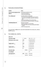
4<br />
Technical Data<br />
<strong>Minarc</strong> <strong>220</strong><br />
Mains voltage<br />
Rated power<br />
Connection cable<br />
Fuse<br />
Load capacity 40 ºC<br />
Welding range<br />
Open circuit voltage<br />
Idling power<br />
Power ratio at max. current<br />
Efficiency at max. current<br />
TIG<br />
MMA<br />
MMA<br />
TIG<br />
MMA<br />
TIG<br />
MMA<br />
TIG<br />
MMA<br />
TIG<br />
MMA<br />
TIG<br />
MMA<br />
3 ~ 400 V –20 %... +15 %, 50/60 Hz<br />
7.2 kVA (<strong>220</strong> A/18,8 V)<br />
8.2 kVA (<strong>220</strong> A/28.8 V)<br />
5x1.5 mm² S - 5 m<br />
10 A delayed<br />
35 % ED <strong>220</strong> A/28.8 V<br />
100 % ED 150 A/26 V<br />
35 % ED <strong>220</strong> A/18.8 V<br />
100 % ED 160 A/16,4 V<br />
10 A/20,4 V-<strong>220</strong> A/28,8 V<br />
10 A/10.4 V-<strong>220</strong> A/18.8 V<br />
85V (30V for VRD)<br />
60V (30V for VRD)<br />
40W<br />
0.92<br />
0.91<br />
0.80<br />
0.86<br />
MMA welding electrodes<br />
MMA<br />
Ø 1.5-5.0 mm<br />
External dimensions<br />
L×W×H<br />
400 × 180 × 340<br />
Weight<br />
9,2 kg (10,2 kg with mains cable)<br />
Recommended generator<br />
> 20 kVA
5<br />
General<br />
Connection 400 V -20%....+15%<br />
10A fuse slow<br />
Generator usage 20kVA<br />
H-bridge inverter topology<br />
Internal operating frequency 30kHz<br />
Large voltage reserve enables the use of all kinds<br />
of MMA electrodes:<br />
Basic, rutile and cellulose electrodes<br />
Diameters from 1.6 up to 5.0 mm.<br />
Extended power range enables welding of thicker<br />
materials<br />
Suitable remote controllers are R10 and RTC10
6<br />
Panel functions<br />
1. Power on indication lamp<br />
2. Overheat signal lamp (Also indicates net voltage errors)<br />
3. Welding process selection (MMA or TIG)<br />
4. Control method selection (Remote or local)<br />
5. Welding current adjustment knob<br />
6. Welding settings table
Main circuit diagram<br />
7
Construction left side<br />
8<br />
1 A001 Control card<br />
2 Z004 Filter card<br />
3 P001 Panel card<br />
4 M001 Cooling fan
9<br />
Construction right side<br />
1 Z001 Main circuit card<br />
2 Z002 Secondary card<br />
3 S001 Main switch
Bottom view<br />
10<br />
1 T001 Main transformer
11<br />
Top view<br />
1 T002 Auxiliary transformer<br />
2 Z003 Relay card
Block diagram<br />
Z004<br />
-Secondary side voltages/current<br />
filtering (capacitors C1, C3, C5)<br />
-varistor/capacitor protection<br />
circuits against HF ignition<br />
disturbances<br />
-EMC filtering<br />
Z002<br />
-Main trafo T001<br />
sec. voltages<br />
rectifier<br />
-Main trafo T001<br />
aux. coil voltages<br />
rectifier<br />
12<br />
A001<br />
-Processor unit<br />
-Power stage control<br />
-Aux. Devices control<br />
-Machine overheat protection<br />
-Over- and undervoltage monitoring<br />
-Cooling fan control<br />
-Aux. Voltages developement<br />
Z001<br />
-DC-link capacitors &<br />
charging<br />
-Powerstage (Hbridge)<br />
-Primary recitifier V1<br />
-EMI-filtering (choke<br />
L1+<br />
capacitors C1-C6)<br />
P001<br />
-Button S3 (welding method selection)<br />
-button S4 (local/remote control<br />
selection)<br />
-led H1 (power on)<br />
Led H2 (overheat/error)<br />
Z003<br />
-Power<br />
switching relays<br />
-Varistors (R4-<br />
R6) protection<br />
against net<br />
spikes
Main components<br />
13<br />
Main switch (9761225)<br />
one phase flip flop switch<br />
connected to Z003<br />
Auxilary transformer<br />
T003 (9777931)<br />
400V / 18V (18VA)<br />
Main transformer<br />
T001 (SP002979)<br />
1 primary coils (20 turns)<br />
2 secondary coils (2 turns)<br />
2 lifting coils (11 turns)
14<br />
Main components<br />
Secondary choke<br />
L002 (SP002755)<br />
Cooling fan M001 (SP600049)
15<br />
Thermal protection<br />
RG101 Overheat protection PTC<br />
• In the primary heat sink<br />
• Temperature limit 90 0 C<br />
• Resistance in +20 C temperature<br />
~68 Ohms<br />
RG102 Overheat protection PTC<br />
• In the main transformer<br />
• Temperature limit 120 0 C<br />
• Resistance in +20 C<br />
temperature ~66 ohms<br />
RG103 Overheat protection PTC<br />
• In the secondary choke<br />
• Temperature limit 170 0 C<br />
• Resistance in +20 C<br />
temperature ~43 Ohms
Z001<br />
Main circuit card<br />
16<br />
Main components:<br />
Emi filter (Choke L1 + capacitors C1-C6)<br />
Primary (3-phase) rectifier V1<br />
DC-link charging diodes (V2-V5)<br />
DC-link capacitors (C7+C9)<br />
IGBT module V6 ( H-bridge, fourback module )
Z001<br />
Main circuit card<br />
(SP002317)<br />
17<br />
Primary rectifier<br />
IGBT module<br />
Tightening the heatsink screws:<br />
1. Stage torque 1 Nm<br />
2. Stage torque 3 Nm
18<br />
Z002<br />
Secondary diode card<br />
(SP002991)<br />
Components<br />
Secondary rectifiers & their heatsink<br />
Mounting screw tightening torque 1,2 Nm
19<br />
Z003<br />
Relay card<br />
(SP002683)<br />
3~phase relay card with main switch<br />
and protection varistors
20<br />
Z004<br />
Filter card<br />
(SP002989)<br />
Secondary side voltage/current filtering
21<br />
A001<br />
Control card<br />
(SP002826)<br />
Auxiliary voltages development<br />
Processor<br />
Remote/torch control lines<br />
Power stage control
22<br />
Measurements and tests<br />
Secondary diode testing possibilities:<br />
1. Measuring via the machine connectors
23<br />
Measurements and tests<br />
Secondary diode testing possibilities:<br />
2. Measuring directly on the secondary diode card
24<br />
Measurements and tests<br />
Main transformer´s primary coil continuity test
25<br />
Measurements and tests<br />
The primary rectifier can be tested with a multimeter<br />
by diode test
26<br />
Measurements and tests<br />
DC-link voltage measured from the prim. rectifier´s<br />
secondary connections. The voltage is approx. 540 VDC.
Notes<br />
27