Kempact Pulse™
- No tags were found...

Create successful ePaper yourself
Turn your PDF publications into a flip-book with our unique Google optimized e-Paper software.
<strong>Kempact</strong> Pulse<br />
3000 MVU<br />
Operating manual • English<br />
Bruksanvisning • Norsk<br />
EN<br />
NO
<strong>Kempact</strong> Pulse 3000 MVU / © Kemppi Oy / 1026<br />
Operating manual<br />
English<br />
EN
<strong>Kempact</strong> Pulse 3000 MVU / © Kemppi Oy / 1026<br />
EN<br />
Contents<br />
1. PREFACE.......................................................................................3<br />
1.1 General..................................................................................................................................................................3<br />
1.2 Product introduction..................................................................................................................................3<br />
1.3 General Safety Instructions....................................................................................................................3<br />
2. BEFORE YOU START USING THE UNIT .......................................6<br />
2.1 Unpacking..........................................................................................................................................................6<br />
2.2 Placement of the unit.................................................................................................................................6<br />
2.3 Serial number...................................................................................................................................................6<br />
2.4 Connection to the mains supply........................................................................................................6<br />
2.5 Distribution network..................................................................................................................................6<br />
2.6 Ground cable....................................................................................................................................................6<br />
2.7 DuraTorque 400, 4 wheel wire feed mechanism................................................................7<br />
2.8 Installation of welding gun....................................................................................................................8<br />
2.9 Mounting and locking of wire reel...................................................................................................8<br />
2.10 Automatic wire feed to gun...................................................................................................................8<br />
2.11 Adjustment of pressure............................................................................................................................8<br />
2.12 Adjustment of tightness of spool brake.......................................................................................9<br />
2.13 Shielding gas....................................................................................................................................................9<br />
3. OPERATION................................................................................ 10<br />
3.1 Main switch and signal lights............................................................................................................10<br />
3.2 To select polarity for welding............................................................................................................10<br />
3.2.1 Changing the polarity.......................................................................................................................10<br />
3.3 Panel....................................................................................................................................................................11<br />
3.3.1 Choosing start switch function.....................................................................................................11<br />
3.3.2 Choosing the welding method.....................................................................................................11<br />
3.3.3 Selecting 1-mig/pulse mig synergy curves...............................................................................12<br />
3.3.4 Adjustments, display and weld data...........................................................................................13<br />
3.3.5 Timer.......................................................................................................................................................14<br />
3.3.6 Adjustment of welding dynamics................................................................................................14<br />
3.3.7 Remote control...................................................................................................................................14<br />
3.3.8 MIG extra functions...........................................................................................................................14<br />
3.3.9 Use of gas test......................................................................................................................................15<br />
3.3.10 Testing wire feed................................................................................................................................15<br />
3.3.11 Memory channels, MEMORY..........................................................................................................15<br />
3.3.12 SETUP......................................................................................................................................................16<br />
3.3.13 Error codes............................................................................................................................................17<br />
4. MAINTENANCE.......................................................................... 18<br />
4.1 Daily maintenance.....................................................................................................................................18<br />
4.2 Regular maintenance..............................................................................................................................18<br />
4.3 Disposal of the machine........................................................................................................................18<br />
5. ORDERING NUMBERS............................................................... 19<br />
6. TECHNICAL DATA...................................................................... 20<br />
7. WARRANTY POLICY................................................................... 21<br />
2
1. PREFACE<br />
1.1 General<br />
Congratulations on your choice of the <strong>Kempact</strong> Pulse series power source. Reliable<br />
and durable, Kemppi products are affordable to maintain, and they increase your work<br />
productivity.<br />
This user manual contains important information on the use, maintenance, and safety of<br />
your Kemppi product. The technical specifications of the device can be found at the end of<br />
the manual. Please read the manual carefully before using the equipment for the first time.<br />
For your safety and that of your working environment, pay particular attention to the safety<br />
instructions in the manual.<br />
For more information on Kemppi products, contact Kemppi Oy, consult an authorised Kemppi<br />
dealer, or visit the Kemppi Web site at www.kemppi.com.<br />
The specifications presented in this manual are subject to change without prior notice.<br />
Important notes<br />
Items in the manual that require particular attention in order to minimise damage and<br />
personal harm are indicated with the ’NOTE!’ notation. Read these sections carefully and follow<br />
their instructions.<br />
<strong>Kempact</strong> Pulse 3000 MVU / © Kemppi Oy / 1026<br />
1.2 Product introduction<br />
The <strong>Kempact</strong> Pulse 3000 MVU is a compact MIG inverter suitable for repair and installation<br />
use, and for light and medium industrial use.<br />
1.3 General Safety Instructions<br />
Kemppi welding equipments conform to international safety standards. Safety is an important<br />
issue in equipment design and manufacturing. Therefore, Kemppi welding solutions are<br />
unparalleled in safety. There are, however, always certain hazards involved in using welding<br />
equipment. Therefore, to ensure your personal safety and the safety of your working<br />
environment, carefully read the safety instructions below and respect them.<br />
Use of personal protective equipment<br />
• The arc and its reflecting radiation damage unprotected eyes. Shield your eyes and<br />
face appropriately before you start welding or observe welding. As the welding current<br />
increases, the welding face screen lens darkness should also increase.<br />
• Arc radiation and spatters burn unprotected skin. Always wear protective gloves,<br />
clothing and footwear when welding.<br />
• Always wear hearing protection if the ambient noise level exceeds the allowable limit<br />
(e.g., 85 dB).<br />
General operating safety<br />
• Exercise caution when handling parts heated during welding. For example, the tip of<br />
the welding torch or gun, and the end of the welding rod and the work piece. The<br />
temperature of items burn unprotected skin.<br />
• Never wear any welding device on the shoulder during welding and never suspend it by<br />
the carrying strap during welding.<br />
• Do not expose the machine to high temperatures, as this may cause damage.<br />
• Keep intermediate and earth return cables as close to each other as possible throughout<br />
their length. Straighten any loops in the cables as this limits inductive effects on welding<br />
performance. This also minimizes your exposure to harmful magnetic fields, which may,<br />
for example, interfere with a pacemaker.<br />
• Do not wrap the welding cables around your body.<br />
• In environments classified as dangerous, only use S-marked welding equipments with<br />
a safe idle voltage level. These work environments include, for example, humid, hot or<br />
small spaces, where the user may be directly exposed to the surrounding conductive<br />
materials.<br />
• Do not use arc welding equipment for pipe thawing.<br />
EN<br />
3
<strong>Kempact</strong> Pulse 3000 MVU / © Kemppi Oy / 1026<br />
EN<br />
Spatter and fire safety<br />
• Welding is always classified as hot work, so pay particular attention to the fire safety<br />
regulations during welding and after it.<br />
• Remember that fire can break out from sparks, even several hours after the welding work<br />
is completed.<br />
• Protect the environment from welding spatter. Remove combustible materials, such as<br />
flammable liquid from the welding vicinity, and supply the welding site with adequate<br />
fire fighting equipment.<br />
• In special welding jobs, be prepared for hazards such as fire or explosion when welding<br />
inside enclosed work spaces, such as tanks and vessels. Ensure you have authority to<br />
work.<br />
• Never direct the sparks or cutting spray of a grinder toward the welding machine or<br />
flammable materials.<br />
• Beware of hot objects or spatter falling on the machine when working above. Welding in<br />
flammable or explosive sites is absolutely forbidden.<br />
General electric safety<br />
• Only connect the welding machine to an earthed electric network. Note the<br />
recommended mains fuse size.<br />
• Do not take the welding machine inside a container, vehicle or similar work piece unless<br />
authorized to do so.<br />
• Do not place the welding machine on a wet surface and do not work on a wet surface.<br />
• Do not allow the mains cable to be directly exposed to water.<br />
• Ensure cables or welding torches are not squashed by heavy objects and that they are<br />
not exposed to sharp edges or a hot work piece.<br />
• Make sure that faulty and damaged welding torches are changed immediately as they<br />
may cause electrocution or fire.<br />
• Remember that the cable, plugs and other electric devices may be installed or replaced<br />
only by an electrical contractor or engineer authorized to perform such operations.<br />
• Turn off the welding machine when it is not in use.<br />
Welding power circuit<br />
• Insulate yourself from the welding circuit by using dry and undamaged protective<br />
clothing.<br />
• Never touch the work piece and welding rod, welding wire, welding electrode or contact<br />
tip at the same time.<br />
• Do not put the welding torch or ground cable on the welding machine or other electric<br />
equipment.<br />
Welding fumes<br />
• Ensure proper ventilation and avoid inhaling the fumes.<br />
• Ensure a sufficient supply of fresh air, particularly in closed spaces. You can also ensure<br />
an adequate supply of clean breathing air by using a filtered fresh-air mask.<br />
• Take extra precautions when working on metals or surface-treated materials containing,<br />
for example, lead, cadmium, zinc, mercury or beryllium.<br />
Transportation, lifting and suspension<br />
• Pay attention to correct working position when lifting a heavy device – risk of injury to<br />
the back.<br />
• Never pull or lift the machine by the welding torch or other cables. Always use the lifting<br />
points or handles designed for that purpose.<br />
• Only use a transport unit designed for the equipment. Try to transport the machine in an<br />
upright position, if possible.<br />
• Never lift a gas cylinder and the welding machine at the same time. There are separate<br />
provisions for gas cylinder transportation.<br />
• Never use a welding machine when suspended unless the suspension device has been<br />
designed and approved for that particular purpose.<br />
• Do not exceed the maximum allowable load of suspension beams or the transportation<br />
trolley of welding equipment. It is recommended that the wire coil be removed during<br />
lifting or transportation.<br />
4
Environment<br />
• Welding equipment is not recommended for use in rain or snow – see manual. Protect<br />
the equipment against rain and strong sunlight. Always store the machine in a dry and<br />
clean space.<br />
• Protect the machine from sand and dust during use and in storage. The recommended<br />
operating temperature range is -20 to +40 °C. The machine’s operation efficiency<br />
decreases and it becomes more prone to damage if used in temperatures in excess of<br />
40 °C.<br />
• Place the machine so that it is not exposed to hot surfaces, sparks or spatter.<br />
• Make sure the airflow to and from the machine is unrestricted.<br />
• EMC classification of this product is class A in accordance with electromagnetic<br />
compatibility standards CISPR 11 and IEC 60974-10, and therefore the product is<br />
designed to be used in an industrial environment only.<br />
WARNING: This class A equipment is not intended for use in residential locations where<br />
the electrical power is provided by a public low-voltage supply system. In those locations<br />
it may be difficult to ensure the electromagnetic compatibility due to conducted and<br />
radiated disturbances.<br />
• Arc welding equipments cause electromagnetic disturbance. To minimize the harmful<br />
effects, strictly use the equipment according to the operating manual and other<br />
recommendations.<br />
Gas bottles and pneumatic devices<br />
• Adhere to the instructions for handling pneumatic devices and gas bottles.<br />
• Make sure that gas bottles are used and stored in properly ventilated spaces.<br />
• A leaking gas bottle may replace the breathable air, causing suffocation.<br />
• Before use, make sure that the gas bottle contains gas suitable for the intended welding<br />
purpose.<br />
• Always fix the gas bottle securely in an upright position, against a bottle wall rack or<br />
purpose-made bottle cart.<br />
• Never move a gas bottle when the regulator or flow adjuster is in place. Replace the<br />
valve cover during transportation. Close the bottle valve after use.<br />
Circuit diagram and spare part lists<br />
If the circuit diagram and the spare parts list are not included in delivery package, please<br />
inquire for them at your local Kemppi service representative. For more information, please visit<br />
www.kemppi.com.<br />
Disclaimer<br />
While every effort has been made to ensure that the information contained in this guide<br />
is accurate and complete, no liability can be accepted for any errors or omissions. Kemppi<br />
reserves the right to change the specification of the product described at any time without<br />
prior notice. Do not copy, record, reproduce or transmit the contents of this guide without<br />
prior permission from Kemppi.<br />
<strong>Kempact</strong> Pulse 3000 MVU / © Kemppi Oy / 1026<br />
EN<br />
5
<strong>Kempact</strong> Pulse 3000 MVU / © Kemppi Oy / 1026<br />
2. BEFORE YOU START USING THE UNIT<br />
2.1 Unpacking<br />
The equipment is packed in durable packages, designed specially for it. Nevertheless, before<br />
using the equipment, always make sure it was not damaged during transport. Also check that<br />
you have received what you ordered and it is accompanied by the appropriate instructions.<br />
NOTE! The packaging material is suitable for recycling.<br />
2.2 Placement of the unit<br />
Place the unit on a horizontal, solid, and clean surface. Shield it from heavy rain and scorching<br />
sun. Make sure that cooling air circulates freely.<br />
2.3 Serial number<br />
The serial number of the unit is marked on its rating plate. The serial number makes it possible<br />
to trace product manufacturing series. You might need the serial number when placing spare<br />
parts orders or when planning maintenance.<br />
2.4 Connection to the mains supply<br />
The <strong>Kempact</strong> Pulse 3000 MVU is delivered with a five metre mains cable without a plug.<br />
Installation of the plug should be carried out only by a competent electrician. <strong>Kempact</strong> Pulse<br />
MVU can be connected to mains supply of 230 V 3~ or 400 V 3~ power source. Power source<br />
recognizes the mains voltage automaticly. For fuse and cable sizes, see the technical data in<br />
the end of this document.<br />
2.5 Distribution network<br />
All regular electrical devices without special circuits generate harmonic currents into<br />
distribution network. High rates of harmonic current may cause losses and disturbance to<br />
some equipment.<br />
Connection to 400 V supply:<br />
WARNING: This equipment does not comply with IEC 61000-3-12. If it is connected to a public<br />
low voltage system, it is the responsibility of the installer or user of the equipment to ensure,<br />
by consultation with the distribution network operator if necessary, that the equipment may<br />
be connected.<br />
2.6 Ground cable<br />
Fasten the earth clamp of the return current cable carefully, preferably direct onto the piece to<br />
be welded. The contact surface of the earth clamp should always be as large as possible.<br />
Clean the fastening surface of paint and rust. Use at least two 35 mm² cables. Thinner cross<br />
sectional areas may cause the connectors to overheat.<br />
EN<br />
6
2.7 DuraTorque 400, 4 wheel wire feed mechanism<br />
Wire guide tubes<br />
Ss, Al, Fe, ø 0.6 ... 1.6 mm<br />
Mc, Fc<br />
ø 1.6 ... 2.4 mm<br />
ø 2.5/64 mm,<br />
W000762,<br />
silver, plastic<br />
ø 3.5/64 mm,<br />
W001430,<br />
silver, plastic<br />
Fe, Mc, Fc ø 0.6 ... 0.8 mm ø 1.0/67 mm,<br />
W001432,<br />
white, steel<br />
ø 0.9 ... 1.6 mm<br />
ø 2.0/64 mm,<br />
W001433,<br />
orange, steel<br />
ø 1.6 ... 2.4 mm<br />
ø 4.0/63 mm,<br />
W001434,<br />
blue, steel<br />
ø 2.5/33 mm,<br />
W000956,<br />
silver, plastic<br />
ø 3.5/33 mm,<br />
W001431,<br />
silver, plastic<br />
ø 2.0/33 mm,<br />
W001435,<br />
orange, steel<br />
ø 4.0/33 mm,<br />
W001436,<br />
blue, steel<br />
ø 2.0 mm,<br />
W000624,<br />
plastic<br />
ø 3.5 mm,<br />
W001389,<br />
plastic<br />
ø 2.0 mm,<br />
W000624,<br />
plastic<br />
ø 3.5 mm,<br />
W001389,<br />
plastic<br />
ø 3.5 mm,<br />
W001391,<br />
brass<br />
<strong>Kempact</strong> Pulse 3000 MVU / © Kemppi Oy / 1026<br />
2.<br />
1.<br />
Wire feed rolls<br />
ø mm colour drawing pressing<br />
Fe, Ss, Al, 0.6 pale grey W001045 W001046<br />
V-groove 0.8/0.9 white W001047 W001048<br />
1.0 red W000675 W000676<br />
1.2 orange W000960 W000961<br />
1.4 brown W001049 W001050<br />
1.6 yellow W001051 W001052<br />
2.0 grey W001053 W001054<br />
2.4 black W001055 W001056<br />
Fe, Fc, Mc, 1.0 red W001057 W001058<br />
knurled 1.2 orange W001059 W001060<br />
1.4/1.6 yellow W001061 W001062<br />
2.0 grey W001063 W001064<br />
2.4 black W001065 W001066<br />
Fe, Fc, Mc, 1.0 red W001067 W001068<br />
Ss, Al, 1.2 orange W001069 W001070<br />
U-groove<br />
1.6 yellow W001071 W001072<br />
EN<br />
7
<strong>Kempact</strong> Pulse 3000 MVU / © Kemppi Oy / 1026<br />
2.8 Installation of welding gun<br />
Make sure the gun wire conduit and the contact tip match the manufacturer’s<br />
recommendations for the type and diameter of wire you use. Too small a conduit may<br />
overload the wire feed device and impede the wire feeding. Tighten the gun’s quick connector<br />
to eliminate voltage loss. A loose joint will heat up the gun and wire heater.<br />
Note! Never use defected gun.<br />
2.9 Mounting and locking of wire reel<br />
LOCKED<br />
OPEN<br />
• Release locking nails of wire reel hub by turning locking knob a quarter round.<br />
• Mount the reel at its place. Note rotating direction of reel!<br />
• Lock the reel with locking knob, locking nails of hub remain to outside position and will<br />
lock the reel.<br />
2.10 Automatic wire feed to gun<br />
Automatic wire feed makes change of wire reel more rapid. In reel change the pressure of feed<br />
rolls need not to be released and filler wire goes automatically to correct wire line.<br />
• Make sure that groove of feed roll matches the diameter of welding wire used.<br />
• Release the wire end from reel and cut off the bent length. Be careful that the wire does<br />
not spill from the reel to sides!<br />
• Straighten about 20 cm of the wire and see that the end of it has no sharp edges (file<br />
off if necessary). A sharp edge may damage the wire guide tube and contact tip of the<br />
welding gun.<br />
• Draw a bit of loose wire from wire reel. Feed wire through back liner to feed rolls. Do not<br />
release pressure of feed rolls!<br />
• Press the gun switch and feed a bit wire until wire goes through feed rolls to gun. See<br />
that wire is in grooves of both feed roll pairs!<br />
• Press still the gun switch until wire has come through contact tip.<br />
Automatic feed may sometimes fail with thin wires (Fe, Fc, Ss: 0,6...0,8 mm, Al: 0,8...1,0 mm). In<br />
that case you might have to open feed rolls and feed wire manually through feed rolls.<br />
Note! Check that the wire or wire reel does not touch the equipment body, there is a danger of<br />
short circuit<br />
EN<br />
2.11 Adjustment of pressure<br />
Adjust the pressure of the feed rolls with the control screw so that the wire is fed into the wire<br />
guide tube evenly and allows a little braking when emerging from the contact tip, without<br />
slipping on the feed rolls.<br />
Note! Excessive pressure will cause the filler wire to flatten and damage its coating, as well as<br />
undue wear and tear of the feed rolls and friction damage.<br />
8
2.12 Adjustment of tightness of spool brake<br />
Brake force can be adjusted through the hole in the spool hub’s locking device of spool hub by<br />
screwing the control screw with a screwdriver. Adjust the braking force so that it is sufficient<br />
to prevent the wire from becoming too loose on the spool and spilling when the spool stops<br />
rotating. The greater the wire feed speed, the greater the braking force required. Do not keep<br />
the brake unnecessarily tight, since this will impose a strain on the motor.<br />
2.13 Shielding gas<br />
The MIG shielding gas consists of carbon dioxide, mixed gases and argon. Shielding gas<br />
flow rate is determined by the amount of welding current. The typical flow rate of gas in the<br />
welding steel is 8-15 l /min.<br />
Parts of gas flow regulator<br />
<strong>Kempact</strong> Pulse 3000 MVU / © Kemppi Oy / 1026<br />
A<br />
C<br />
F<br />
G<br />
B<br />
E<br />
D<br />
A. Gas bottle valve<br />
B. Press regulation screw<br />
C. Connecting nut<br />
D. Hose spindle<br />
E. Jacket nut<br />
F. Gas bottle pressure meter<br />
G. Gas hose pressure meter<br />
The following installation instructions are valid for most gas flow regulator types:<br />
1. Step aside and open the bottle valve (A) for a while to blow out possible impurities.<br />
2. Turn the press regulation screw (B) of the regulator until no spring pressure can be felt.<br />
3. Close the needle valve if there is one in the regulator.<br />
4. Install the regulator onto bottle valve and tighten the connecting nut (C) with a wrench.<br />
5. Install the hose spindle (D) and jacket nut (E) into the gas hose and tighten with a hose<br />
clamp.<br />
6. Connect the hose with the regulator and the other end with the wire feed unit. Tighten<br />
jacket nut.<br />
7. Open the bottle valve slowly. The gas bottle pressure meter (F) shows bottle pressure.<br />
Note! Do not use the whole contents of the bottle. The bottle pressure should be filled<br />
when bottle pressure is 2 bar.<br />
EN<br />
9
<strong>Kempact</strong> Pulse 3000 MVU / © Kemppi Oy / 1026<br />
8. Open the needle valve if there is one in the regulator.<br />
9. Turn the regulation screw (B) until the hose pressure meter (G) displays the required flow<br />
(or pressure). When regulating the flow amount, the power source should be switched<br />
on and the "GAS PURGE" -switch pressed simultanously.<br />
Close the bottle valve after welding is finished. If the machine will not be in use for a long<br />
time, unscrew the pressure regulation screw.<br />
Note! Always fasten the gas cylinder securely in an upright position on a wall rack intended for the<br />
purpose or on a cylinder cart. Always close the cylinder valve after you have finished welding.<br />
3. OPERATION<br />
3.1 Main switch and signal lights<br />
With the switch in the ’I’ position, the primary and control circuits of the machine become<br />
live and the ’ON’ signal light on the panel lights up. The welding circuit receives voltage when<br />
the gun switch is operated or when the wire feed test switch is pressed. Always use the main<br />
switch to turn the machine on and off with the main switch; do not use the power plug for this<br />
purpose.<br />
3.2 To select polarity for welding<br />
Solid wire is usually welded in the +pole and gasfree filler wires in the - pole gun. When<br />
welding with other filler wires, check for the recommended polarity on the package or consult<br />
the supplier of the product. The welding of very thin steelplates (0.5 to 0.7 mm) a - polarity<br />
might also work best for solid wire.<br />
3.2.1 Changing the polarity<br />
- pole<br />
+ pole<br />
Note! Only a service shop authorised by Kemppi may change the polarity.<br />
EN<br />
10
3.3 Panel<br />
<strong>Kempact</strong> Pulse 3000 MVU / © Kemppi Oy / 1026<br />
3.3.1 Choosing start switch function<br />
MIG welding by 4-function start switch, MIG 4T<br />
MIG welding by 2 function start switch, MIG 2T<br />
3.3.2 Choosing the welding method<br />
Normal MIG/MAG welding:<br />
With a separate wire feed and voltage regulation can be chosen in the 1-MIG position. Curve<br />
number ”00” provides a free wire feed range between 1-18 m/min. The voltage can be set<br />
between special pre-programmed limits depending on the wire feed. Curve number ”01” wire<br />
feed speed and voltage are not depended on each other. When curve ”01” is selected, the wire<br />
feed speed and voltage will be independent of one another.<br />
Synergic MIG/MAG welding (1-MIG)<br />
Synergic MIG/MAG welding (1-MIG): MIG welding in which the wire feed speed determines all<br />
the other welding parameter values, allowing the adjustment of welding power with a single<br />
knob. Choose the appropriate synergy curve for the filler wire and shielding gas to determine<br />
how the wire feed speed affects the pulse parametres.<br />
Synergic Pulse MIG welding:<br />
Through this welding method, based on pulsing the welding current, the filler metal on the<br />
workpiece is kept spatter-free. The power source pulse parameters change automatically<br />
(synergy) enabling welding power regulation using a single knob. Choose the appropriate<br />
synergy curve for the filler wire and shielding gas to determine how the wire feed speed<br />
affects the pulse parametres.<br />
11<br />
EN
<strong>Kempact</strong> Pulse 3000 MVU / © Kemppi Oy / 1026<br />
Double pulse:<br />
The wire feed will become higher or lower according to the wire feed range. While the<br />
synergic welding parameters change to correspond to the momentary wire speed. The<br />
purpose is to get a goodlooking weld and a proper penetration while improving the<br />
controllability of the weld pool during position welding.<br />
3.3.3 Selecting 1-mig/pulse mig synergy curves<br />
The program number of the synergy curve is selected using the plus-minus buttons and is<br />
displayed on ”SYNERGIC PRG”.<br />
The middle display is actual material group display (eg. SS, AL, CUS, FE, GEN). Wire diameter<br />
(mm) can be seen on the right side. This information will only be displayed for a while.<br />
The ”PRG INFO” button gives more curve information:<br />
One press will revert to the material group and diameter display, a second will display the type<br />
number of the material and a third run through the gas consistency components one by one.<br />
<strong>Kempact</strong> Pulse 3000 Synergic programs<br />
1-MIG Pulse Double Wire, ø Material Gas Wire Feed Range<br />
Pulse<br />
00 All All All 1,0 - 18,0<br />
01 All All All 0,5 - 18,0<br />
SS-group<br />
S1 S1 S1 0,8 mm SS 308 / 316 Ar + 2 % CO ²<br />
S2 S2 S2 0,9 mm SS 308 / 316 Ar + 2 % CO ²<br />
S3 S3 S3 1,0 mm SS 308 / 316 Ar + 2 % CO ²<br />
S4 S4 S4 1,2 mm SS 308 / 316 Ar + 2 % CO ²<br />
S5 0,9 mm SS 316 FC Ar + 18 % CO ²<br />
EN<br />
S7 1,2 mm SS 316 FC Ar + 18 % CO ²<br />
Al-group<br />
A1 A1 A1 1,0 mm AlMg5 / AlMg4,5Mn Ar<br />
A2 A2 A2 1,2 mm AlMg5 / AlMg4,5Mn Ar<br />
A6 A6 A6 1,0 mm AlSi5 / AlSi12 Ar<br />
A7 A7 A7 1,2 mm AlSi5 / AlSi12 Ar<br />
Cu-group<br />
C1 C1 C1 0,8 mm CuSi3 Ar<br />
C2 C2 C2 0,9 mm CuSi3 Ar<br />
C3 C3 C3 1,0 mm CuSi3 Ar<br />
C4 C4 C4 1,2 mm CuSi3 Ar<br />
C5 C5 C5 0,8 mm CuAl8 Ar<br />
C6 C6 C6 0,9 mm CuAl8 Ar<br />
C7 C7 C7 1,0 mm CuAl8 Ar<br />
C8 C8 C8 1,2 mm CuAl8 Ar<br />
12
Fe-group<br />
F1 F1 F1 0,8 mm Fe Ar + 18 % CO ²<br />
F2 F2 F2 0,9 mm Fe Ar + 18 % CO ²<br />
F3 F3 F3 1,0 mm Fe Ar + 18 % CO ²<br />
F4 F4 F4 1,2 mm Fe Ar + 18 % CO ²<br />
F5 0,8 mm Fe CO ²<br />
F6 0,9 mm Fe CO ²<br />
F7 1,0 mm Fe CO ²<br />
F8 1,2 mm Fe CO ²<br />
FA FA FA 1,0 mm FeMC Ar + 18 % CO ²<br />
FB FB FB 1,2 mm FeMC Ar + 18 % CO ²<br />
FD 1,2 mm FeFC Ar + 18 % CO ²<br />
Auto<br />
20 20 1,0 mm CuSi3-A Ar 1,1 – 2,0<br />
1 21 21 1,0 mm CuSi3-A Ar 2,0 – 2,6<br />
2 22 22 1,0 mm CuSi3-A Ar 2,4 – 3,1<br />
3 23 23 1,0 mm CuSi3-A Ar 3,0 – 3,6<br />
4 24 24 1,0 mm CuSi3-A Ar 3,5 – 4,1<br />
5 25 25 1,0 mm CuSi3-A Ar 4,0 – 4,6<br />
6 26 26 1,0 mm CuSi3-A Ar 4,5 – 5,1<br />
7 27 27 1,0 mm CuSi3-A Ar 5,0 – 5,5<br />
8 28 28 1,0 mm CuSi3-A Ar 5,5 – 6,0<br />
9 29 29 1,0 mm CuSi3-A Ar 6,0 – 6,5<br />
10 30 30 1,0 mm CuSi3-A Ar 6,4 – 7,0<br />
11 31 31 1,0 mm CuSi3-A Ar 6,9 – 7,6<br />
12 32 32 1,0 mm CuSi3-A Ar 7,4 – 8,1<br />
<strong>Kempact</strong> Pulse 3000 MVU / © Kemppi Oy / 1026<br />
3.3.4 Adjustments, display and weld data<br />
Display for welding current and welding material thickness. Changing can be made using the<br />
button behind the display. There is a percentage display (eg. gas consistency) and seconds<br />
display (see timer). The relative length of arc will be displayed when adjusted. Otherwise the<br />
predicted current value is displayed (not in 2-MIG).<br />
Process Manager for setting all welding parameters.<br />
The display for wire feed speed, welding voltage or material group. This can be switched using<br />
the button under the display (wire feed speed/length of arc). The voltage can be adjusted<br />
in the normal and 1-MIG position (wire feed range/the length of arc). During pulse welding<br />
the voltage is determined by the wire feed speed while the length of arc affects some other<br />
parameters.<br />
When pressed simultaneously, the weld data buttons recall the wire feed speed on the display,<br />
the welding voltage and welding current values which have been used when welding was<br />
stopped.<br />
EN<br />
13
<strong>Kempact</strong> Pulse 3000 MVU / © Kemppi Oy / 1026<br />
3.3.5 Timer<br />
Intermittent welding<br />
Spot welding<br />
The spot time is set immediately after pressing the switch button, on the display SPt. The<br />
pause time is set accordingly, on the PSE display. The time is set using the Process Manager.<br />
3.3.6 Adjustment of welding dynamics<br />
For adjusting of MIG/MAG welding dynamics, the adjustment value dyn -9...0...9 is displayed.<br />
The welding stability and quantity of spatter are affected by the welding dynamics control,<br />
the 0-position is the recommended reference range. Values -9...-1 give a smoother arc and less<br />
spatter, while values 1...9 give a rougher arc and increased stability, when using a 100% CO²<br />
shielding gas when welding steel.<br />
3.3.7 Remote control<br />
Gun control, wire feed speed or welding power control is changed using RMT 10. Control of<br />
the welding voltage or the length of the welding arc can be adjusted using the potentiometer<br />
on the panel. Panel control, adjustments using the potentiometer on the panel.<br />
3.3.8 MIG extra functions<br />
EN<br />
Crater filling, 1-MIG and pulse MIG:<br />
Crater filling reduces welding mistakes caused by end craters. By pressing the 4T-trigger<br />
continuously at the end of weld, a descending welding power is achieved which fills end<br />
craters in a controlled manner. The descending time is kept constant using the 2T function,<br />
and the welding power and end level can be changed using the SETUP-function.<br />
Hot Start<br />
Crater filling<br />
Wire range/<br />
power/Welding<br />
current<br />
Start switch 4T<br />
14
The Hot Start:<br />
The Hot Start function is used with 1-MIG and pulse MIG welding. The Hot Start time by 4T<br />
Hot Start time is determined by trigger function (see picture) and while by 2T function it<br />
is determined by the SETUP parameters. The level of Hot Start can be changed by SETUP<br />
function.<br />
The Hot Start level, Hot Start time by 2T, crater fill level and downslope time can be easily<br />
adjusted using the ‘QUICK SETUP’ function:<br />
1. Select the gun trigger function: 4T or 2T.<br />
2. First, press the SETUP button and then , while still pressing the SETUP button, press the<br />
extra function button.<br />
3. Adjust the Hot Start level.<br />
4. Repeat step 2, upon which the display will show the next adjustable parameter,<br />
depending on the switch mode.<br />
Exit by pressing any button (except SETUP)<br />
3.3.9 Use of gas test<br />
<strong>Kempact</strong> Pulse 3000 MVU / © Kemppi Oy / 1026<br />
If you press the gas test button, gas will begin to flow without any starting power source or<br />
wire feed. Gas flow can be measured by using an external measuring device.<br />
Cut off the gas flow by pressing the same button again, or the gun trigger. If the trigger is not<br />
pressed again, the gas flow will end within 20 seconds.<br />
The display will show “GAS” and the time.<br />
3.3.10 Testing wire feed<br />
The wire feed switch will start the wire feed motor without opening the gas valve. The power<br />
source will start up, but without providing welding power. The wire feed range will be 5m/<br />
min but can be adjusted as desired.<br />
3.3.11 Memory channels, MEMORY<br />
The pulse panel has 100 channels for different welding options. Memory channels can be<br />
chosen on the lower part of the panel using the memory block. Both welding values and<br />
functions can be saved. Do the following:<br />
EN<br />
15
<strong>Kempact</strong> Pulse 3000 MVU / © Kemppi Oy / 1026<br />
1. Press twice if needed and and the SET light will start blinking if the channel is<br />
not in use, while the light will stay on if the channel is in use.<br />
2. Select the memory channel you want by pressing CH button<br />
3. Make settings and save by pressing SAVE button.<br />
4. Press twice. ON light turns on.<br />
5. Start welding and set the values.<br />
To change the values, the light must be switched from the ON to SET and then you can choose<br />
the parameters, pressing the SAVE button afterwards. It is also possible to save the used<br />
parameters by pressing SET when memory function is OFF (no lights). The channel can be<br />
emptied by pressing<br />
Using saved settings<br />
and SET button in SET simultaneously.<br />
1. Press button.<br />
2. Select the memory channel by pressing the CH button.<br />
3. Start welding.<br />
Memory channels in control device<br />
Select memory channels by pressing the CH REMOTE button simultaneously and the gun<br />
control light will start to blink. Use the saved values through the gun’s remote control.<br />
You can use five channels.<br />
3.3.12 SETUP<br />
Using the SETUP function, the user can change welding parameters which do not have their<br />
own panel functions. These parameters can be set separately for 1-MIG and Pulse MIG. SETUP<br />
settings are separate for each memory channel.<br />
Setup functions on pulse panel<br />
EN<br />
Parameter Name Nr Display 1-MIG Pulsed<br />
MIG<br />
Factory<br />
value<br />
Unit<br />
Explanation<br />
PostGasTime 1 PoG X X Curve s PostGas time 0.0…9.9 s<br />
PreGasTime 2 PrG X X Curve s PreGas time, functions by 2T<br />
0.0…9.9 s<br />
HotStartLevel 11 Hot X X 30 % Hot start ratio to welding power<br />
-50…+75%<br />
HotStartTime 2T 12 H2t X X 2 s 2T Hot start timer 0.1-9.9 s<br />
CraterFillLevel 14 CFL X X 30 % Welding end level 10-90 %<br />
CraterFillSlope 15 CFS X X 1 s/10m Wire slowing-down<br />
1…20 s/10m<br />
CreepStartLevel 17 CSL X X Syn Wire speed start value 10…90<br />
CreepStartSlope 18 CSS X X 0 s/10m Wire speed up time<br />
0.1…5 s/10m<br />
DoubleFrequency 21 dFr X Curve Hz Double pulse frequency control<br />
0.4…8.0 Hz<br />
DoubleAmpiltude 22 dA X Curve m/min Double pulse power variation<br />
control 0.1…3.0 m/min<br />
StartPower 31 StP X X 0 Start power control<br />
-9…0…+9<br />
PulseCurrent 33 PuC X 0 % Pulse top current control<br />
-10…+15%<br />
ArcLength<br />
AdjRange<br />
41 ALr X X 0 % Arc length adjustment range<br />
-50…+75%<br />
16
Calibration 42 CAL X X 1 V/100A Setting mid value of arc length<br />
fine adjustment 0.0…10.0<br />
V/100A<br />
WFS 51 FS 18 m/min Wire feed maximum<br />
18 or 25 m/min<br />
Gun 53 Gun On Liquidcooled thermal protection<br />
on/off<br />
GunRemote 54 GrE On Disabling of gun remote control<br />
automatic identification<br />
Water Cooler<br />
On/Off Selection<br />
55 Coo On Set OFF after each power up if<br />
cooler is connected with gas<br />
cooled gun.<br />
Display reset time 81 dLY X X 5 s 1...20 s<br />
PRG INFO - feeld 82 diS X X 1 1, 2, 3<br />
selection<br />
Restore 99 FAC X OFF Restoring factory settings<br />
(OFF=no reset,<br />
Pan=panel and setup<br />
ALL= also memory channels)<br />
<strong>Kempact</strong> Pulse 3000 MVU / © Kemppi Oy / 1026<br />
Changing parameters<br />
By pressing the 2T/4T (SETUP) selection switch a little longer the machine will enter the SETUP<br />
state. The display will show the set parameter’s runnning number (blinking), its abbreviation<br />
and value. Select the parameter number using the “SYNERGIC PRG” + and - buttons or the<br />
“SETUP” button (which will jump by tens). Change the value using the control button (in some<br />
cases, the value can be found from the synergy curve). “Syn” and the curve value will blink by<br />
turns on the right of the display. Set the value by turning the button anticlockwise.<br />
Exit for SETUP using a long press.<br />
Frequency and amplitude of double pulse can be set in the separate ‘SET’ mode, obtained<br />
by first pressing the 2T/4T (SETUP) and, without releasing it, the method button. “dFr” and<br />
the frequency in Hz will be displayed. “Syn” will appear if the frequency is based on synergy<br />
curves. Change this value by turning the control button anticlockwise. Press it twice to display<br />
“dA” i.e. the amplitude (m/min). Adjust this accordingly and exit SETUP by pressing any button<br />
other than SETUP.<br />
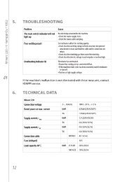
3.3.13 Error codes<br />
Error codes are among others the following:<br />
Err 3: Overvoltages in the mains supply. Also the pilot light of overvoltage is lighting.<br />
Err 4: The thermal protection of power suorce has stopped welding. Also the pilot light of<br />
thermal protection is lighting.<br />
Err 5: The cooling device has stopped welding.<br />
Err 6: The terminal voltage has rised. Take the device to service.<br />
Err 153: Liquid cooled PMT- or WS-gun is overheated. Or torch-PTC or RMT10 has beeb<br />
installed, but the jumber inside the torch is in FU-position, look also instruction of torch.<br />
Err 154: Overloading of the wire feed motor<br />
Error code is eliminated when the reason is aborted, except Err 6, which demands to turn<br />
down the machine.<br />
EN<br />
17
<strong>Kempact</strong> Pulse 3000 MVU / © Kemppi Oy / 1026<br />
4. MAINTENANCE<br />
4.1 Daily maintenance<br />
Note! Be careful of mains voltage when handling electric cables!<br />
Clean the wire channel of the gun and check the contact tip regularly. Always check the<br />
condition of the mains and welding cable before operation and replace defective cables.<br />
Note! Only a qualified electrician should remove or install the mains cable!<br />
4.2 Regular maintenance<br />
KEMPPI -service workshops sign special service contracts with customers for regular<br />
maintenance. All parts are cleaned, checked and if necessary, repaired. The operation of the<br />
welding machine is also tested.<br />
4.3 Disposal of the machine<br />
Do not dispose of electrical equipment with normal waste!<br />
In observance of European Directive 2002/96/EC on waste electrical and electronic<br />
equipment, and its implementation in accordance with national law, electrical equipment<br />
that has reached the end of its life must be collected separately and taken to an appropriate<br />
environmentally responsible recycling facility.<br />
The owner of the equipment is obliged to deliver a decommissioned unit to a regional<br />
collection centre, per the instructions of local authorities or a Kemppi representative. By<br />
applying this European Directive you will improve the environment and human health.<br />
EN<br />
18
5. ORDERING NUMBERS<br />
Item<br />
Ordering number<br />
<strong>Kempact</strong> Pulse 3000 MVU 62183000302<br />
GH 30 Gun holder 6256030<br />
PMT 25 3 m 6252513<br />
PMT 25 4,5 m 6252514<br />
PMT 27 3 m 6252713<br />
PMT 27 4,5 m 6252714<br />
PMT 32 3 m 6253213<br />
PMT 32 4,5 m 6253214<br />
PMT 35 3 m 6253513<br />
PMT 35 4,5 m 6253514<br />
WS 35 6 m Al1,2 6253516A12<br />
WS 35 6 m Ss1,0 6253516S10<br />
MMT 25 3 m 6252513MMT<br />
MMT 25 4,5 m 6252514MMT<br />
MMT 27 3 m 6252713MMT<br />
MMT 27 4,5 m 6252714MMT<br />
Remote Control Unit RMT 10 6185475<br />
Earth cable 35 mm² 5 m 6184311<br />
Transport unit P20 power source and gas bottle 6185261<br />
Transport unit P250 power source 6185268<br />
Lift hook 4298180<br />
Gas hose 6 m W000566<br />
Wire spool pole 4289880<br />
5 kg spool adapter 4251270<br />
<strong>Kempact</strong> Pulse 3000 MVU / © Kemppi Oy / 1026<br />
Parts of the DuraTorque 400 metal feed rolls<br />
W000731 gear ring 1 driving 2 pcs per unit<br />
W000732 gear ring 2 pressing 2 pcs per unit<br />
W000711 drive ring V groove 1,2/1,2 optional 4 pcs per unit<br />
W000718 drive ring V groove 1,0/1,0 optional 4 pcs per unit<br />
W000891 drive ring V groove 1,0/1,2 4 pcs per unit<br />
9420507 washer 10.5x30x2.5 2 pcs per unit<br />
Recommended for aluminium welding with Pulse MIG.<br />
EN<br />
19
<strong>Kempact</strong> Pulse 3000 MVU / © Kemppi Oy / 1026<br />
EN<br />
6. TECHNICAL DATA<br />
<strong>Kempact</strong> Pulse 3000 MVU<br />
Mains connection 3~, 50/60 Hz 230 V +/-10%<br />
3~, 50/60 Hz 400 V +/-15%<br />
Connected load<br />
40% ED 10 kVA 250 A<br />
60% ED 8 kVA 207 A<br />
100% ED 6,5 kVA 160 A<br />
Connection cable HO7RN-F 4G1.5 (5 m)<br />
Fuse (delayed)<br />
16A<br />
Load capacity<br />
40% ED 250 A /26,5 V<br />
60% ED 207 A /24 V<br />
100% ED 160 A /22 V<br />
Adjustment range<br />
8 - 30 V<br />
Wire feed speed<br />
1 - 18 m/min<br />
Open circuit voltage<br />
68 V<br />
Power factor 0,78 (250 A / 26,5 V)<br />
Efficiency 0,83 (250 A / 26,5 V)<br />
Filler wires<br />
Fe, Ss<br />
0,6 ... 1,2 mm<br />
Cored wire<br />
0,9 ... 1,2 mm<br />
Al<br />
0,9 ... 1,2 mm<br />
CuSi<br />
0.8 ... 1.2 mm<br />
Shielding gas<br />
CO ² , Ar, Ar & CO ² mixed gases<br />
Wire spool diameter<br />
300 mm (15 kg)<br />
Feed roll Ø<br />
32 mm<br />
Thermal class<br />
H (180 °C) / B (130 °C)<br />
External dimensions LxWxH 580x280x600 mm<br />
Weight<br />
33 kg<br />
Gun connector<br />
EURO<br />
Principle of operation<br />
4-wheel feed<br />
Range of temperature for use - 20 °C ...+ 40 °C<br />
Storage temperature for use - 40 °C ...+ 60 °C<br />
EMC class<br />
A<br />
Degree of protection<br />
IP23S<br />
20
7. WARRANTY POLICY<br />
Kemppi Oy provides a warranty for products manufactured and sold by the company if defects<br />
in materials or workmanship occur. Warranty repairs are to be carried out only by an authorised<br />
Kemppi Service Agent. Packing, shipping, and insurance are at the orderer’s expense.<br />
The warranty starts on the date of purchase. Spoken promises not included in the terms of<br />
warranty are not binding on the warrantor.<br />
Limitations of the warranty<br />
The following conditions are not covered under the terms of warranty: defects arising<br />
from normal wear and tear, non-compliance with operation and maintenance instructions,<br />
overloading, negligence, connection to incorrect or faulty supply voltage (including voltage<br />
surges outside equipment specifications), incorrect gas pressure, anomalies or failures in the<br />
electric network, transport or storage damage, and fire or damage due to forces of nature. This<br />
warranty does not cover direct or indirect travel costs, daily allowances, or accommodation<br />
related to warranty service.<br />
The warranty does not cover welding torches and their consumables, feeder drive rolls, and<br />
feeder guide tubes. Direct or indirect damage caused by a defective product is not covered<br />
under the warranty.<br />
The warranty becomes void if modifications are made to the machine that are not approved<br />
by the manufacturer or if non-original spare parts are used in repairs. The warranty is also<br />
voided if repairs are carried out by a repair agent not authorised by Kemppi.<br />
Undertaking warranty repairs<br />
Warranty defects must be reported to Kemppi or an authorised Kemppi Service Agent without<br />
delay.<br />
Before a warranty repair is undertaken, the customer must present proof of warranty or<br />
otherwise prove the validity of the warranty in writing. The proof must indicate the date of<br />
purchase and the manufacturing number of the unit to be repaired. The parts replaced under<br />
the terms of this warranty remain the property of Kemppi and must be returned to Kemppi if<br />
requested.<br />
After a warranty repair, the warranty of the machine or equipment, repaired or replaced, shall<br />
be continued to the end of the original warranty period.<br />
<strong>Kempact</strong> Pulse 3000 MVU / © Kemppi Oy / 1026<br />
EN<br />
21
KEMPPI OY<br />
Hennalankatu 39<br />
PL 13<br />
FIN-15801 LAHTI<br />
FINLAND<br />
Tel +358 3 899 11<br />
Telefax +358 3 899 428<br />
export@kemppi.com<br />
www.kemppi.com<br />
Kotimaan myynti:<br />
Tel +358 3 899 11<br />
Telefax +358 3 734 8398<br />
myynti.fi@kemppi.com<br />
KEMPPI SVERIGE AB<br />
Box 717<br />
S-194 27 UPPLANDS VÄSBY<br />
SVERIGE<br />
Tel +46 8 590 783 00<br />
Telefax +46 8 590 823 94<br />
sales.se@kemppi.com<br />
KEMPPI NORGE A/S<br />
Postboks 2151, Postterminalen<br />
N-3103 TØNSBERG<br />
NORGE<br />
Tel +47 33 346000<br />
Telefax +47 33 346010<br />
sales.no@kemppi.com<br />
KEMPPI DANMARK A/S<br />
Literbuen 11<br />
DK-2740 SKOVLUNDE<br />
DANMARK<br />
Tel +45 4494 1677<br />
Telefax +45 4494 1536<br />
sales.dk@kemppi.com<br />
KEMPPI BENELUX B.V.<br />
Postbus 5603<br />
NL-4801 EA BREDA<br />
NEDERLAND<br />
Tel +31 765717750<br />
Telefax +31 765716345<br />
sales.nl@kemppi.com<br />
KEMPPI (UK) Ltd<br />
Martti Kemppi Building<br />
Fraser Road<br />
Priory Business Park<br />
BEDFORD, MK44 3WH<br />
ENGLAND<br />
Tel +44 (0)845 6444201<br />
Telefax +44 (0)845 6444202<br />
sales.uk@kemppi.com<br />
KEMPPI FRANCE S.A.S.<br />
65 Avenue de la Couronne des Prés<br />
78681 EPONE CEDEX<br />
FRANCE<br />
Tel +33 1 30 90 04 40<br />
Telefax +33 1 30 90 04 45<br />
sales.fr@kemppi.com<br />
KEMPPI GmbH<br />
Otto-Hahn-Straße 14<br />
D-35510 BUTZBACH<br />
DEUTSCHLAND<br />
Tel +49 6033 88 020<br />
Telefax +49 6033 72 528<br />
sales.de@kemppi.com<br />
KEMPPI SPÓŁKA Z O.O.<br />
Ul. Borzymowska 32<br />
03-565 WARSZAWA<br />
POLAND<br />
Tel +48 22 7816162<br />
Telefax +48 22 7816505<br />
info.pl@kemppi.com<br />
KEMPPI AUSTRALIA PTY LTD.<br />
13 Cullen Place<br />
P.O. Box 5256, Greystanes NSW 2145<br />
SMITHFIELD NSW 2164<br />
AUSTRALIA<br />
Tel. +61 2 9605 9500<br />
Telefax +61 2 9605 5999<br />
info.au@kemppi.com<br />
OOO KEMPPI<br />
Polkovaya str. 1, Building 6<br />
127018 MOSCOW<br />
RUSSIA<br />
Tel +7 495 739 4304<br />
Telefax +7 495 739 4305<br />
info.ru@kemppi.com<br />
ООО КЕМППИ<br />
ул. Полковая 1, строение 6<br />
127018 Москва<br />
Tel +7 495 739 4304<br />
Telefax +7 495 739 4305<br />
info.ru@kemppi.com<br />
KEMPPI, TRADING (BEIJING) COMPANY,<br />
LIMITED<br />
Room 420, 3 Zone, Building B,<br />
No.12 Hongda North Street,<br />
Beijing Economic Development Zone,<br />
100176 Beijing<br />
CHINA<br />
Tel +86-10-6787 6064<br />
+86-10-6787 1282<br />
Telefax +86-10-6787 5259<br />
sales.cn@kemppi.com<br />
肯 倍 贸 易 ( 北 京 ) 有 限 公 司<br />
中 国 北 京 经 济 技 术 开 发 区 宏 达 北 路 12 号<br />
创 新 大 厦 B 座 三 区 420 室 (100176)<br />
电 话 : +86-10-6787 6064<br />
+86-10-6787 1282<br />
传 真 : +86-10-6787 5259<br />
sales.cn@kemppi.com<br />
KEMPPI INDIA PVT LTD<br />
LAKSHMI TOWERS<br />
New No. 2/770,<br />
First Main Road,<br />
KAZURA Gardens,<br />
Neelangarai,<br />
CHENNAI - 600 041<br />
TAMIL NADU<br />
Tel +91-44-4567 1200<br />
Telefax +91-44-4567 1234<br />
sales.india@kemppi.com<br />
www.kemppi.com<br />
19101811<br />
1026